

Texas Instruments PT78NR103V, PT78NR105H, PT78NR105S, PT78NR105V, PT78NR107H Datasheet
...
For assistance or to order, call (800) 531-5782
PT78NR100
Series
1 AMP PLUS TO MINUS VOLTAGE
INTEGRATED SWITCHING REGULATOR
Application Notes
Mechanical Outline
Product Selector Guide
Revised 5/15/98
• Negative output from positive input
• Wide Input Range
• Self-Contained Inductor
• Short Circuit Protection
• Over-Temperature Protection
• Fast Transient Response
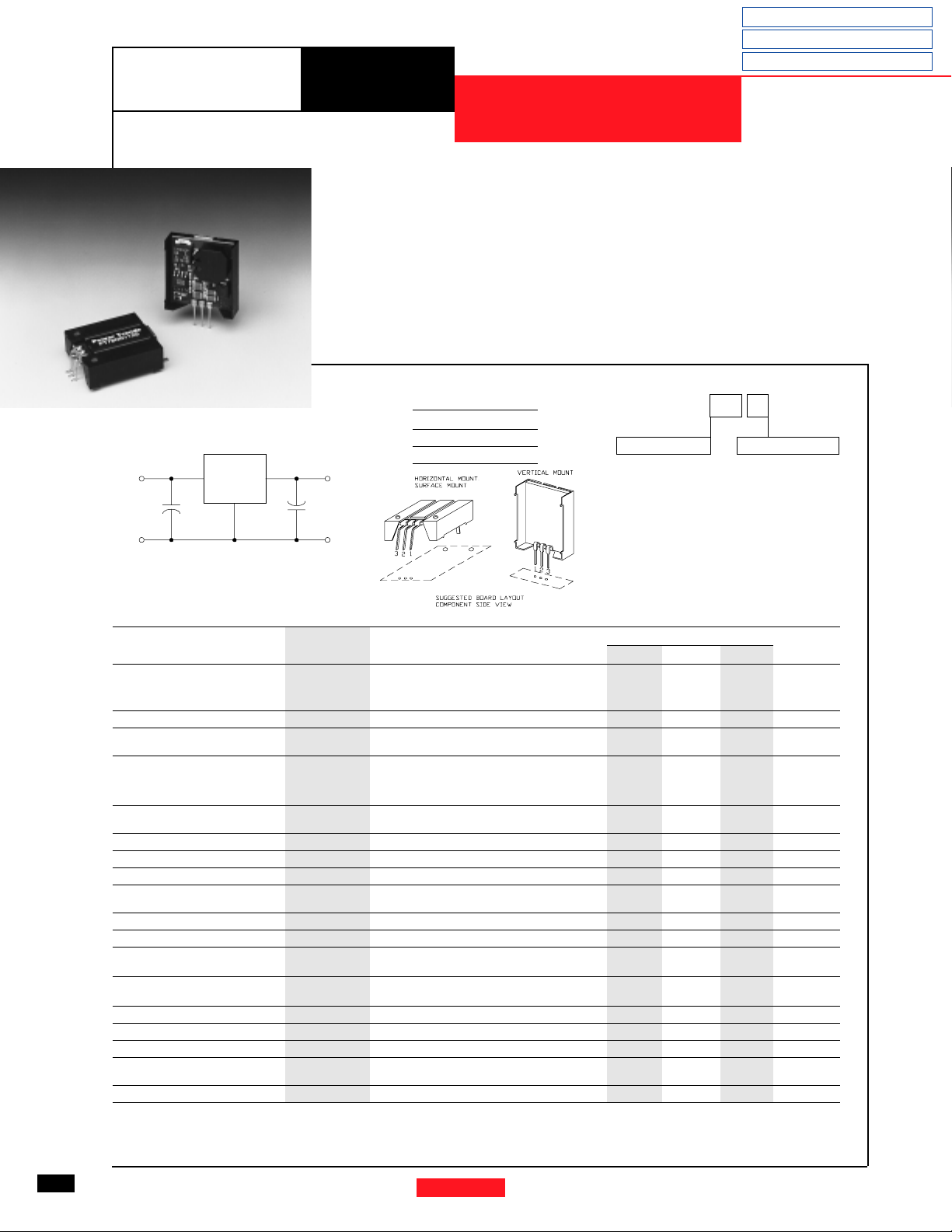
The PT78NR100 Series creates a
negative output voltage from a positive
input voltage greater than 7V. These
easy-to-use, 3-terminal, Integrated
Switching Regulators (ISRs) have
maximum output power of 5 watts and
a negative output voltage that is laser
trimmed. They also have excellent line
and load regulation.
Pin-Out Information
Pin Function
1+V
Standard Application
Vin
C1
1
PT78NR100
+
C1 = Required 100µF electrolytic
C2 = Required 100µF electrolytic
3
-Vout
2
C2
+
COMCOM
Specifications
Characteristics
(Ta= 25°C unless noted) Symbols Conditions Min Typ Max Units
Output Current I
Short Circuit Current I
Inrush Current I
Input Voltage Range V
Output Voltage Tolerance ∆V
Line Regulation Reg
Load Regulation Reg
V
Ripple/Noise V
o
Transient Response t
(with 100µF output cap) Vo over/undershoot — 5.0 — %V
Efficiency η Vin=10V, Io=0.5×I
Switching Frequency ƒ
Absolute Maximum T
Operating Temperaturte Range Over Vin and Io Ranges
Recommended Operating T
Temperature Range Over Vin and Io Ranges
Thermal Resistance θ
Storage Temperature T
Mechanical Shock — Per Mil-STD-883D, Method 2002.3 — 500 — G’s
Mechanical Vibration — Per Mil-STD-883D, Method 2007.2,
Weight — — — 6.5 Grams
*ISR will operate down to no load with reduced specifications. **See Thermal Derating chart.
Note:
The PT78NR100 Series requires a 100µF electrolytic or tantalum output capacitor for proper operation in all applications.
o
sc
ir
t
ir
in
o
line
load
n
tr
o
a
a
ja
s
Over Vin range Vo=-5V 0.05* — 1.00 A
Vin=10V — 4×I
Vin=10V — 4 — A
On start-up — 0.5 — mSec
0.1 ≤ Io ≤ I
Over Vin range
Ta=-20°C to +70°C
Over Vin range — ±0.5 ±1.0 %V
0.1 ≤ Io ≤ I
Vin=10V, Io=I
50% load change — 100 250 µSec
Over Vin and Io ranges 600 650 700 kHz
Free Air Convection, (40-60LFM)
Free Air Convection, (40-60LFM)
Free Air Convection, (40-60LFM) — 45 — °C/W
— -40 — +125 °C
20-2000 Hz, soldered in a PC board
in
2-V
out
3 GND
Pkg Style 500
=-7, -8, -9V 0.05* — 0.55 A
V
o
=-12V 0.05* — 0.40 A
V
o
Vo=-15V 0.05* — 0.30 A
=-5V 7 — 25 V
maxVo
=-7, -8, -9V 7 — 21 V
V
o
V
=-12V 7 — 18 V
o
Vo=-15V 7 — 15 V
max
max
= -5V — 75 — %
max, Vo
Ordering Information
PT78NR1
Output Voltage
03 = -3.0 Volts
05 = -5.0 Volts
52 = -5.2 Volts
07 = -7.0 Volts
08 = -8.0 Volts
09 = -9.0 Volts
12 = -12.0 Volts
15 = -15.0 Volts
PT78NR100 SERIES
— ±1.0 ±3.0 %V
— ±0.5 ±1.0 %V
—±2—%V
-40 — +85 °C
-40 — +60** °C
—5
max
XX Y
Package Suffix
V = Vertical Mount
S = Surface Mount
H = Horizontal
Mount
— Apk
—
o
o
o
o
o
G’s
14
Power Trends, Inc. 27715 Diehl Road, Warrenville, IL 60555 (800) 531-5782 Fax: (630) 393-6902 http://www.powertrends.com
For assistance or to order, call (800) 531-5782
PT78NR100 Series
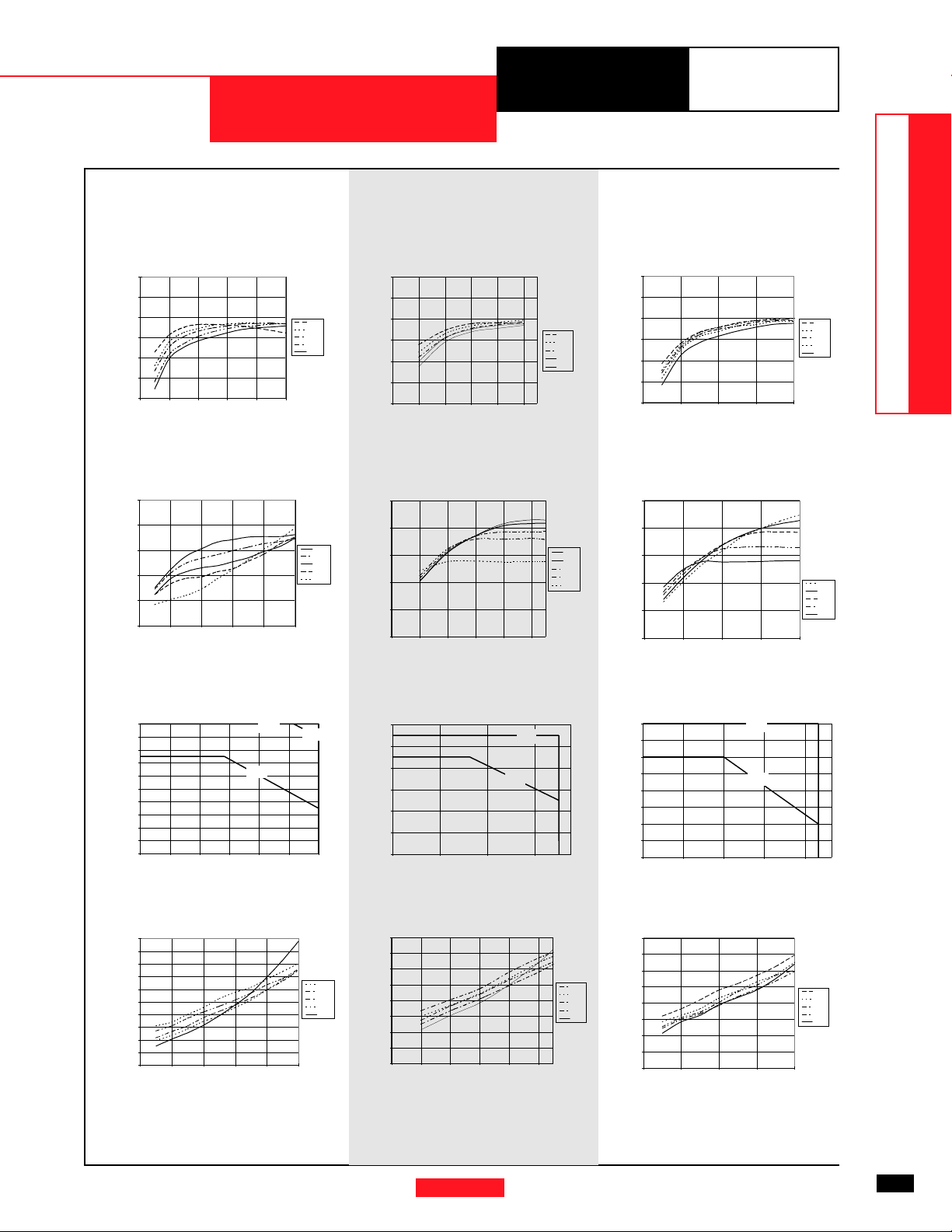
CHARACTERISTIC DATA
PT78NR105 -5.0 VDC (See Note 1) PT78NR109 -9.0 VDC (See Note 1) PT78NR112 -12.0 VDC (See Note 1)
Wide Input Range Products
DATA SHEETS
Efficiency vs Output Current Efficiency vs Output Current
100
90
80
70
60
Efficiency - %Ripple-(mV)Iout-(Amps)PD-(Watts)
50
40
0 0.2 0.4 0.6 0.8 1
Iout-(Amps)
Vin
7.0V
12.0V
15.0V
20.0V
25.0V
100
90
80
70
Efficiency - %
60
50
40
0 0.1 0.2 0.3 0.4 0.5
Iout-(Amps)
Ripple vs Output Current
200
160
120
80
40
0
0 0.2 0.4 0.6 0.8 1
Iout-(Amps)
Vin
25.0V
20.0V
15.0V
12.0V
7.0V
200
160
120
80
Ripple-(mV)
40
0
0 0.1 0.2 0.3 0.4 0.5
Iout-(Amps)
Thermal Derating (Ta) (See Note 2) Thermal Derating (Ta) (See Note 2)
1
0.9
0.8
0.7
0.6
0.5
0.4
0.3
0.2
0.1
0
7 101316192225
85°C
60°C
70°C
Vin-(Volts) Vin-(Volts)Vin-(Volts)
0.6
0.5
0.4
0.3
Iout-(Amps)
0.2
0.1
0
7 111519
85°C
70°C
Efficiency vs Output Current
100
90
Vin
7.0V
12.0V
15.0V
18.0V
21.0V
80
70
60
Efficiency - %
50
40
0 0.1 0.2 0.3 0.4
Vin
7.0V
9.0V
12.0V
15.0V
20.0V
Iout-(Amps)
Ripple vs Output CurrentRipple vs Output Current
250
Vin
21.0V
18.0V
15.0V
12.0V
7.0V
200
150
100
Ripple-(mV)Iout-(Amps)
50
0
0 0.1 0.2 0.3 0.4
Vin
20.0V
15.0V
12.0V
9.0V
7.0V
Iout-(Amps)
Thermal Derating (Ta) (See Note 2)
0.4
0.35
0.3
0.25
0.2
0.15
0.1
0.05
0
7 10131619
70°C
85°C
Power Dissipation vs Output Current
1.6
1.4
1.2
1
0.8
0.6
PD-(Watts)
0.4
0.2
0
0 0.1 0.2 0.3 0.4
2
1.8
1.6
1.4
1.2
1
0.8
0.6
0.4
0.2
0
0 0.2 0.4 0.6 0.8 1
Vin
25.0V
20.0V
15.0V
12.0V
7.0V
Power Dissipation vs Output CurrentPower Dissipation vs Output Current
1.6
1.4
1.2
1
0.8
0.6
PD-(Watts)
0.4
0.2
0
0 0.1 0.2 0.3 0.4 0.5
Vin
21.0V
18.0V
15.0V
12.0V
7.0V
Iout-(Amps) Iout-(Amps) Iout-(Amps)
Note 1: All data listed in the above graphs, except for derating data, has been developed from actual products tested at 25°C. This data is considered typical data for the ISR.
Note 2: Thermal derating graphs are developed in free air convection cooling of 40-60 LFM. (See Thermal Application Notes.)
Power Trends, Inc. 27715 Diehl Road, Warrenville, IL 60555 (800) 531-5782 Fax: (630) 393-6902 http://www.powertrends.com
Vin
20.0V
15.0V
12.0V
9.0V
7.0V
15
 Loading...