

Texas Instruments PT7772A, PT7772C, PT7772N Datasheet
Series
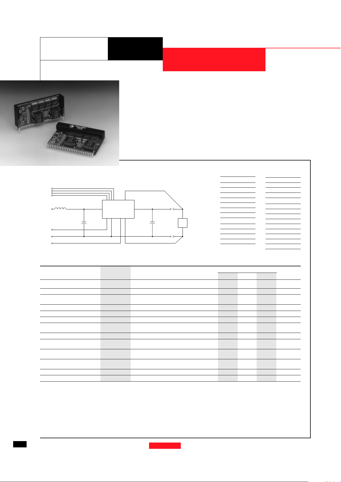
Standard Application
Cin= Required 2400µF electrolytic
C
out
= Required 2400µF electrolytic
L1 = Optional 1µH input choke
32 AMP HIGH-PERFORMANCE
“SLEDGE HAMMER” PROGRAMMABLE ISR
PT7772
The PT7772 is a new series of
high-performance, 32 Amp Integrated
Switching Regulators (ISRs) housed in
a 27-pin SIP package. The 32A capability allows easy
integration of the latest high-speed,
low-voltage µPs, ASICs, DSPs, and
bus drivers into existing 3.3V systems.
The output voltage of the PT7772
can be easily programmed from 1.3V
to 2.05V with a 4-bit input compatible
with Intel’s Pentium
Pro Processor. A
differential remote sense is also provided which automatically compensates
for any voltage drop from the ISR
to the load.
2400µF of output capacitance
are required for proper operation.
For STBY* pin; open = output enabled;
ground = output disabled.
Pin-Out Information
PT7772
7 - 11
13 - 19
20 - 25
27
V
IN
GND
1µH
GND
V
OUT
C
OUT
+
C
IN
+
12
261
L1
SYNC OUT
LOAD
REMOTE SENSE (+)
REMOTE SENSE (-)
VID1
VID2
VID3
PROGRAMMING PINS
234
STBY*
5
VID0
For assistance or to order, call (800) 531-5782
14
Power Trends, Inc. 27715 Diehl Road, Warrenville, IL 60555 (800) 531-5782 Fax: (630) 393-6902 http://www.powertrends.com
Pin Function
1 VID0
2 VID1
3 VID2
4 VID3
5 STBY*- Stand-by
6 Do not connect
7 V
in
8 V
in
9 V
in
10 V
in
11 V
in
12 Remote Sense Gnd
13 GND
Pin Function
14 GND
15 GND
16 GND
17 GND
18 GND
19 GND
20 V
out
21 V
out
22 V
out
23 V
out
24 V
out
25 V
out
26 Remote Sense V
out
27 Sync Out
Specifications
Characteristics
PT7772 SERIES
(T a = 25°C unless noted) Symbols Conditions Min Typ Max Units
Output Current I
o
Ta = +60°C, 200 LFM, pkg N 0.1
(1)
—32A
Ta = +25°C, natural convection 0.1
(1)
—26A
Input Voltage Range V
in
0.1A ≤ I
o
≤ 32A 3.1
(2)
— 3.6 V
Output Voltage Tolerance ∆V
o
V
in
= +3.3V, Io = 32A
V
o-0.03 — Vo+0.03 V
0°C ≤ Ta ≤ +55°C
Line Regulation Reg
line
3.1V ≤ V
in
≤ 3.6V, I
o
= 32A — ±10 — mV
Load Regulation Reg
load
Vin = +3.3V, 0.1 ≤ I
o
≤ 32A — ±10 — mV
Vo Ripple/Noise pk-pk V
n
V
in
= +3.3V, Io = 32A — 50 — mV
Transient Response t
tr
Io step between 16A and 32A — 100 — µSec
with C
out
= 2400µF V
os
Vo over/undershoot — 200 — mV
Efficiency η V
in
= +3.3V, Io = 20A, Vo = 1.8V — 90 — %
Switching Frequency ƒ
o
3.1V ≤ V
in
≤ 3.6V
650 700 750 kHz
0.1A ≤ I
o
≤ 32A
Absolute Maximum T
a
— 0 — +85 °C
Operating Temperature Range
Recommended Operating T
a
Forced Air Flow = 200 LFM
0 — +65 °C
Temperature Range Over V
in and Io
Ranges
Storage Temperature T
s
— -40 — +125 °C
Weight — Vertical/Horizontal — 53/66 — grams
(1) ISR-will operate down to no load with reduced specifications. Please note that this product is not short-circuit protected.
(2) The minimum input voltage is 3.1V or V
out
+1.2V, whichever is greater.
Output Capacitors:
The PT7772 series requires a minimum output capacitance of 2400µF for proper operation. Do not use Oscon type capacitors.
The maximum allowable output capacitance is 30,000µF.
Input Filter:
An input filter is optional for most applications. The input inductor must be sized to handle 32ADC with a typical value of 1µH.
The input capacitance must be rated for a minimum of 2.6Arms of ripple current. For transient or dynamic load applications, additional
capacitance may be required.
Revised 7/15/98

Ordering Information
PT7772
❏❏
❏❏
❏ = 1.3 to 2.05 Volts
Programming Information
VID3 VID2 VID1 VID0 Vout
1 1 1 1 1.30V
1 1 1 0 1.35V
1 1 0 1 1.40V
1 1 0 0 1.45V
1 0 1 1 1.50V
1 0 1 0 1.55V
1 0 0 1 1.60V
1 0 0 0 1.65V
0 1 1 1 1.70V
0 1 1 0 1.75V
0 1 0 1 1.80V
0 1 0 0 1.85V
0 0 1 1 1.90V
0 0 1 0 1.95V
0 0 0 1 2.00V
0 0 0 0 2.05V
Logic 0 = Pin 12 potential (remote sense gnd)
Logic 1 = Open circuit (no pull-up resistors)
VID3 may not be changed while the unit is operating.
For dimensions and PC board layout, see
Package Style 1020 and 1030
• +3.3V input
• 5-bit Programmable:
1.3V to 2.05V@32A
• High Efficiency
• Input Voltage Range:
3.1V to 3.6V
• Differential Remote
Sense
• 27-pin SIP Package
Features
Efficiency vs Output Current (@Vout=+1.8V)
EfEf
EfEf
Ef
ficiency (%)ficiency (%)
ficiency (%)ficiency (%)
ficiency (%)
Output CurOutput Cur
Output CurOutput Cur
Output Cur
rr
rr
r
ent (A)ent (A)
ent (A)ent (A)
ent (A)
Safe Operating Area (@Vin=+3.3V, Vout=+1.8V, Pkg N)
Output CurOutput Cur
Output CurOutput Cur
Output Cur
rr
rr
r
ent (A)ent (A)
ent (A)ent (A)
ent (A)
Ambient TAmbient T
Ambient TAmbient T
Ambient T
emperaturemperatur
emperaturemperatur
emperatur
e (°C)e (°C)
e (°C)e (°C)
e (°C)
Airflow
Recommended Maximum
Operating Temperature
Note: SOA curves represent operating conditions at
which internal components are at or below manufacturer’s
maximum rated operating temperatures.
Power Dissipation vs Output Current (@Vout=+1.8V)
Pd (WPd (W
Pd (WPd (W
Pd (W
atts)atts)
atts)atts)
atts)
Output CurOutput Cur
Output CurOutput Cur
Output Cur
rr
rr
r
ent (A)ent (A)
ent (A)ent (A)
ent (A)
Output Ripple vs Output Current (@Vout=+1.8V)
Ripple (mVpp)Ripple (mVpp)
Ripple (mVpp)Ripple (mVpp)
Ripple (mVpp)
Output CurOutput Cur
Output CurOutput Cur
Output Cur
rr
rr
r
ent (A)ent (A)
ent (A)ent (A)
ent (A)
Vin
Vin
Vin
For assistance or to order, call (800) 531-5782
15
3.3V Bus Products
DATA SHEETS
Power Trends, Inc. 27715 Diehl Road, Warrenville, IL 60555 (800) 531-5782 Fax: (630) 393-6902 http://www.powertrends.com
CHARACTERISTIC DATA
Series
PT7772
PT Series Suffix
(PT1234X)
Case/Pin
Configuration
Vertical Through-Hole N
Horizontal Through-Hole A
Horizontal Surface Mount C
60
70
80
90
100
0 4 8 12 16 20 24 28 32
4.5V
5.0V
5.5V
0
2
4
6
8
10
12
14
16
18
20
0 4 8 121620242832
4.5V
5.0V
5.5V
0
5
10
15
20
25
30
35
40
0 4 8 12 16 20 24 28 32
4.5V
5.0V
5.5V
20
30
40
50
60
70
80
90
0 4 8 12 16 20 24 28 32
Nat. Conv
60 LFM
120 LFM
200 LFM
 Loading...