

For assistance or to order, call (800) 531-5782
Power Trends, Inc. 27715 Diehl Road, Warrenville, IL 60555 (800) 531-5782 Fax: (630) 393-6902 http://www.powertrends.com
28
Application Notes
Mechanical Outline
Product Selector Guide
PT6900 Series
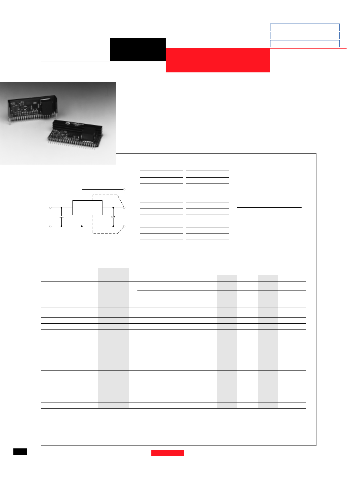
Standard Application
12 WATT PLUS TO MINUS VOLTAGE
CONVERTER
Ordering Information
PT6901
❏❏
❏❏
❏ = -2.0 Volts
PT6902
❏❏
❏❏
❏ = -5.2 Volts
Cin= Required 330µF electrolytic
C
out
= Required 330µF electrolytic
Features
• Single-Device: +5V input
• Remote Sense
• Input Voltage Range:
4.75V to 5.5V
• Adjustable Output Voltage
• 23-pin SIP Package
Pin Function
1 Do not connect
2V
out
Adjust
3V
in
4V
in
5V
in
6V
in
7V
in
8 Remote Sense GND
9 GND
10 GND
11 GND
12 GND
Pin Function
13 GND
14 GND
15 GND
16 V
out
17 V
out
18 V
out
19 V
out
20 V
out
21 V
out
22 Remote Sense V
out
23 Do not connect
Pin-Out Information
The PT6900 is a new series of plus to
minus high- performance, 12 watt voltage
converters housed in a 23-pin SIP package.
The PT6900 is designed to supply
regulated negative voltages for powering the latest ECL (-5.2V) and
GaAs (-2.0V) ICs used in high-speed
fiber optic communications. A 330µF
electrolytic capacitor is required on the
input and output for proper operation.
(For dimensions and PC board layout,
see Package Styles 1100 and 1110.)
CoutCin
PT6900
16-21
9-15
3-7
2
V
ADJ
-V
OUT
GNDGND
+V
IN
+
+
22
Remote Sense
Remote Sense
8
PT Series Suffix
(PT1234X)
Case/Pin
Configuration
Vertical Through-Hole
N
Horizontal Through-Hole
A
Horizontal Surface Mount
C
Specifications
Characteristics
PT6900 SERIES
(Ta= 25°C unless noted) Symbols Conditions Min Typ Max Units
Output Current I
o
Ta = +60°C, 200 LFM, pkg N V
o
= -2.0V 0.1
*
—6 A
V
o
= -5.2V 0.1
*
— 2.5 A
T
a
= +25°C, natural convection V
o
= -2.0V 0.1
*
—6 A
V
o
= -5.2V 0.1
*
— 2.5 A
Input Voltage Range V
in
0.1A ≤ I
o
≤ I
max
4.75 — 5.5 V
Output Voltage Tolerance ∆V
o
V
in
= +5V, Io = I
max
Vo-0.05 — Vo+0.05 V
0°C ≤ Ta ≤ +60°C
Line Regulation Reg
line
4.75V ≤ V
in
≤ 5.5V, I
o
= I
max
— ±0.5 ±1.0 %
Load Regulation Reg
load
Vin = +5V, 0.1 ≤ I
o
≤ I
max
— ±0.5 ±1.0 %
V
o
Ripple/Noise V
n
V
in
= +5V, Io = I
max
V
o
= -2.0V — 40 — mV
V
o
= -5.2V — 10 0 — mV
Transient Response t
tr
Io step between 0.5xI
max
and I
max
— 100 — µSec
with C
out
= 330µF V
os
Vo over/undershoot V
o
= -2.0V — 10 0 — mV
V
o
= -5.2V — 20 0 — mV
Efficiency η V
in
= +5V, Io = 0.5xI
max,
V
o
= -2.0V — 70 — %
Switching Frequency ƒ
o
4.75V ≤ V
in
≤ 5.5V
500
——
kHz
0.1A ≤ I
o
≤ I
max
Absolute Maximum T
a
— 0 — +85 °C
Operating Temperature Range
Recommended Operating T
a
Forced airflow = 200 LFM
0 — +60 °C
Temperature Range Over V
in and Io
Ranges
Storage Temperature T
s
— -40 — +125 °C
Weight — Vertical/Horizontal — 28/33 — grams
* ISR-will operate down to no load with reduced specifications. Please note that this product is not short-circuit protected.
Revised 11/12/98
Note: Case must be connected to
ground pins for proper operation

For assistance or to order, call (800) 531-5782
Power Trends, Inc. 27715 Diehl Road, Warrenville, IL 60555 (800) 531-5782 Fax: (630) 393-6902 http://www.powertrends.com
29
5V to 3.x Converters
5V Bus Products
DATA SHEETS
CHARACTERISTIC DATA
PT6900 Series
Efficiency vs Output Current (@Vin=+5V)
Ripple vs Output Current (@Vin=+5V)
0
5
10
15
20
25
30
35
0123456
40
50
60
70
80
0123456
PT6901, -2.0 VDC
0
1
2
3
4
5
6
7
0123456
Power Dissipation vs Output Current
PD-(Watts) Ripple-(mV)
Iout-(Amps)
Iout-(Amps)
Iout-(Amps)
Efficiency - %
 Loading...