

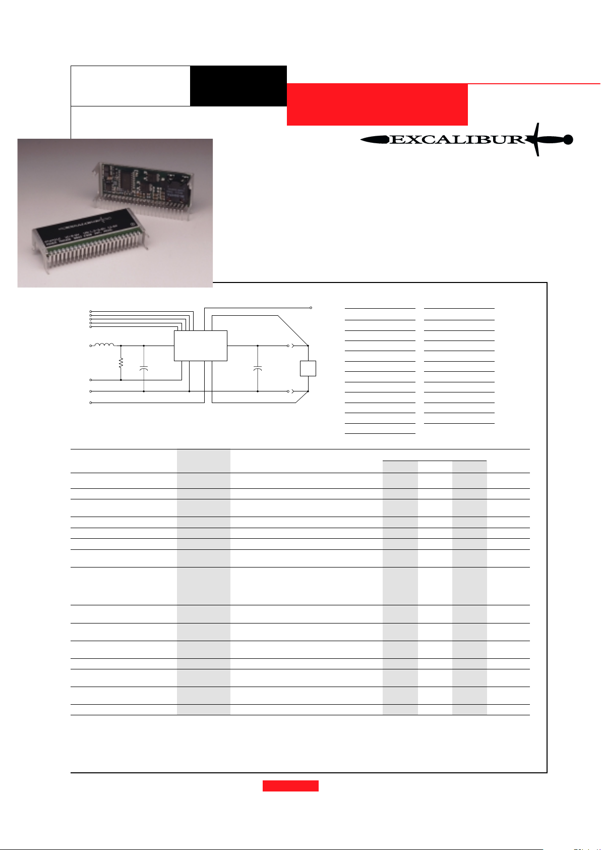
Standard Application
For STBY* pin
open = output enabled
ground = output disabled.
Pin-Out Information
Pin Function
1 OVP Drive
2 Pwr Good
3 VID0
4 VID1
5 VID2
6 VID3
7 VID4
8 STBY*
9 Do not connect
10 V
in
11 V
in
12 V
in
Pin Function
13 Remote Sense Gnd
14 GND
15 GND
16 GND
17 GND
18 GND
19 V
out
20 V
out
21 V
out
22 V
out
23 Remote Sense V
out
PT6700
The PT6700 is a new series of
high-performance, 13 Amp Integrated
Switching Regulators (ISRs) housed in
a unique, space-saving 23-pin SIP
package. The 13A capability allows
easy integration of the latest highspeed, low-voltage µPs and bus drivers
into existing 5V systems.
The output voltage of the PT6700
can be programmed easily from 1.3V
to 3.5V with a 5-bit input compatible
with Intel’s Pentium
II Processor.
The PT6700 includes a differential
remote sense which automatically compensates for any voltage drop from the
ISR to the load. Also provided are
internal short circuit protection,
OVP drive and a power good output
signal. When over-voltage is detected, the PT6700 provides drive for
an external crowbar or other protection circuitry.
For assistance or to order, call (800) 531-5782
Cin= Required 1000µF electrolytic
C
out
= Required 330µF electrolytic
L1 = Optional 1µH input choke
R1 = Required 10kΩ pull-up when using Pwr Good signal. Pwr good
output is high when the output voltage is within specification.
Specifications
Characteristics
PT6700 SERIES
(Ta = 25°C unless noted) Symbols Conditions Min Typ Max Units
Output Current I
o
Ta = +60°C, 200 LFM, pkg N 0.1
*
—13A
Ta = +25°C, natural convection 0.1
*
—13A
Input Voltage Range V
in
0.1A ≤ I
o
≤ 13A 4.5 — 5.5 V
Output Voltage Tolerance ∆V
o
V
in
= +5V, Io = 13A
V
o-0.03 — Vo+0.03 V
-40°C ≤ Ta ≤ +65°C
Line Regulation Reg
line
4.5V ≤ V
in
≤ 5.5V, I
o
= 13A — ±10 — mV
Load Regulation Reg
load
Vin = +5V, 0.1 ≤ I
o
≤ 13A — ±20 — mV
Vo Ripple/Noise V
n
V
in
= +5V, Io = 13A — 50 — mV
Transient Response t
tr
Io step between 6A and 12A — 70 — µSec
with C
out
= 330µF V
os
Vo over/undershoot — 100 — mV
Efficiency η V
in
= +5V, Io = 8A Vo = 3.3V — 91 — %
V
o
= 2.9V — 90 — %
V
o
= 2.5V — 89 — %
V
o
= 1.8V — 85 — %
V
o
= 1.5V — 83 — %
Switching Frequency ƒ
o
4.5V ≤ V
in
≤ 5.5V
300 350 400 kHz
0.1A ≤ I
o
≤ 12.5A
Absolute Maximum T
a
— -40 — +85 °C
Operating Temperature Range
Recommended Operating T
a
Forced Air Flow = 200 LFM
-40 — +65 °C
Temperature Range Over V
in and Io
Ranges
Storage Temperature T
s
— -40 — +125 °C
Mechanical Shock Per Mil-STD-883D, Method 2002.3
1 msec, Half Sine, mounted to a fixture — TBD — G’s
Mechanical Vibration Per Mil-STD-883D, Method 2007.2,
— TBD — G’s
20-2000 Hz, Soldered in a PC board
Weight — — — 26 — grams
* ISR-will operate down to no load with reduced specifications.
Output Capacitors:
The PT6700 series requires a minimum ouput capacitance of 330µF. The maximum allowable output capacitance is 15,000µF.
Input Filter:
An input filter is optional for most applications. The input inductor must be sized to handle 12.5ADC with a typical value of 1µH. The input capacitance must
be rated for a minimum of 1.6Arms of ripple current. For transient or dynamic load applications, additional capacitance may be required.
Revised 9/13/99
Power Trends, Inc. 27715 Diehl Road, Warrenville, IL 60555 (800) 531-5782 Fax: (630) 393-6902 http://www.powertrends.com
PT6700
10 - 12
14 - 18
19 - 22
2
V
IN
GND
1µH
GND
V
OUT
C
OUT
+
C
IN
+
13
233
L1
PWR GOOD
LOAD
REMOTE SENSE (+)
REMOTE SENSE (-)
VID1
VID2
VID3
VID4
PROGRAMMING PINS
456
STBY*
8
7
VID0
OVP DRV
1
R1
13 AMP PROGRAMMABLE
INTEGRATED SWITCHING REGULATOR
Series
Patent pending on package assembly
New Space-Saving Package
Programming Information
VID4=1 VID4=0
VID3 VID2 VID1 VID0 Vout Vout
1 1 1 1 2.0V 1.30V
1 1 1 0 2.1V 1.35V
1 1 0 1 2.2V 1.40V
1 1 0 0 2.3V 1.45V
1 0 1 1 2.4V 1.50V
1 0 1 0 2.5V 1.55V
1 0 0 1 2.6V 1.60V
1 0 0 0 2.7V 1.65V
0 1 1 1 2.8V 1.70V
0 1 1 0 2.9V 1.75V
0 1 0 1 3.0V 1.80V
0 1 0 0 3.1V 1.85V
0 0 1 1 3.2V 1.90V
0 0 1 0 3.3V 1.95V
0 0 0 1 3.4V 2.00V
0 0 0 0 3.5V 2.05V
• Space Saving SIP Package
• +5V input
• 5-bit Programmable:
1.3V to 3.5V@13A
• High Efficiency
• Input Voltage Range:
4.5V to 5.5V
• Differential Remote Sense
• Short Circuit Protection
• Over-Voltage Drive
• Power Good Signal
Features
For assistance or to order, call (800) 531-5782
Power Trends, Inc. 27715 Diehl Road, Warrenville, IL 60555 (800) 531-5782 Fax: (630) 393-6902 http:/www.powertrends.com
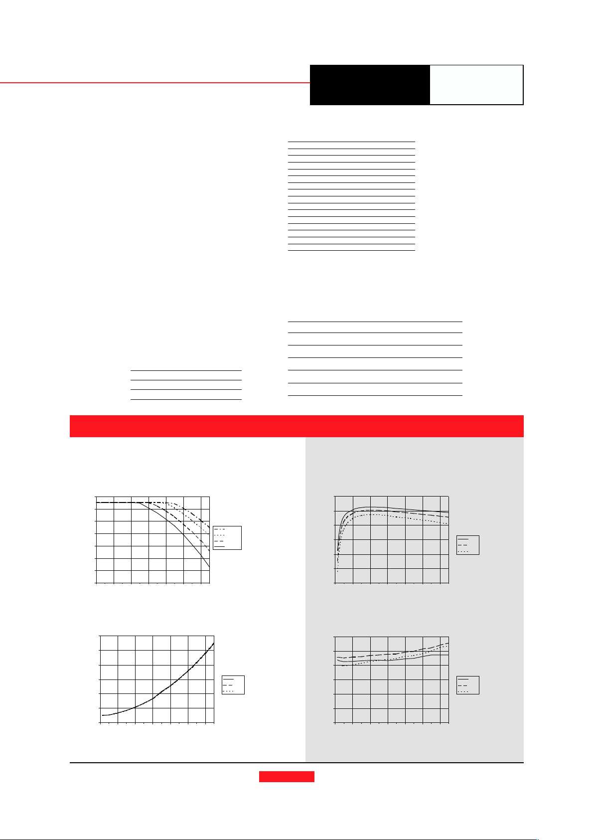
PT6701, Vin = 5.0V (Typical performance at T
a
= 25°C)
Efficiency vs Output Current
Ripple vs Output Current
Power Dissipation vs Output Current
Efficiency (%)Ripple (mV)
Pd (Watts)
Iout (A)
Iout (A)
Iout (A)
Series
Ordering Information
PT6701
❏❏
❏❏
❏ = 1.3 to 3.5 Volts
(For dimensions and PC board layout,
see Package Styles 1300 and 1310.)
PT Series Suffix
(PT1234X)
Case/Pin
Configuration
Vertical Through-Hole
N
Horizontal Through-Hole
A
Horizontal Surface Mount
C
Logic 0 = Pin 13 potential (remote sense gnd)
Logic 1 = Open circuit (no pull-up resistors)
VID3 and VID4 may not be changed while the unit is operating.
PT6700
CHARACTERISTIC DATA
40
50
60
70
80
90
100
024681012
3.3V
2.5V
1.8V
0
5
10
15
20
25
30
024681012
3.3V
2.5V
1.8V
0
1
2
3
4
5
6
024681012
3.3V
2.5V
1.8V
Vout
Vout
Vout
20
30
40
50
60
70
80
90
024681012
200LFM
120LFM
60LFM
Nat co nv
Ambient temperature (°C)
Safe Operating Area, Vout = 3.3V
Iout-(A)
PT6701, Vin = 5.0V
Airflow
PT6700 Product Family
Input Vout OVP/ Requires
Voltage Adjust Pwr Good +12V Bias
PT6701 5V VID
✓✓
✓✓
✓
PT6702 3.3V VID
✓✓
✓✓
✓
PT6705 5V Resistor
✓✓
✓✓
✓
PT6715 5V Resistor
PT6721 12V VID
✓✓
✓✓
✓
PT6725 12V Resistor
 Loading...