

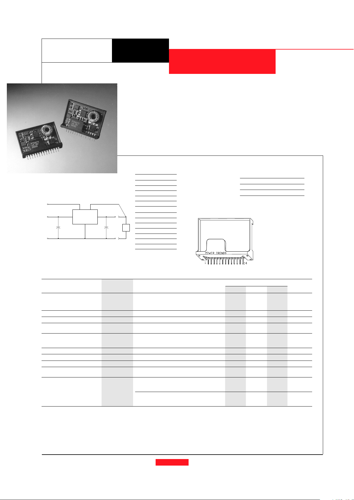
Standard Application
C1 = Required 560µF electrolytic
C2 = Required 560µF electrolytic
PT6670
4,5,6
7,8,9,10
11,12,13
14
V
IN
GND GND
V
OUT
C
2
+
C
1
+
1
VOAdjust
REMOTE SENSE
LOAD
Ordering Information
PT6671¨ = +5.0 Volts
PT6672¨ = +9.0 Volts
PT6673¨ = +12.0 Volts
PT Series Suffix
(PT1234X)
Case/Pin Heat
Configuration Spreader
Vertical Through-Hole
P
Horizontal Through-Hole
D
Horizontal Surface Mount
E
Note: Back surface
of product is
conducting metal.
Pin-Out Information
Pin Function
1 Remote Sense
2 Do not connect
3 Do not connect
4V
in
5V
in
6V
in
7
GND
8 GND
9 GND
10 GND
11 V
out
12 V
out
13 V
out
14 V
out
Adjust
3.3V INPUT 20W BOOST
INTEGRATED SWITCHING REGULATOR
• Input Voltage Range: 3.0 to 3.6V
• Adjustable Output Voltage
• 85% Efficiency
• Remote Sense Capability
• Soft Start
The PT6670 series is a new addition
to the Power Trends high performance
family of 14-Pin SIP (Single In-line
Package) Integrated Switching Regulators (ISRs), designed for 3.3V bus
applications needing 5 to 12 volts for
auxilliary circuits at up to 20W of
output power.
For assistance or to order, call (800) 531-5782
Power Trends, Inc. 27715 Diehl Road, Warrenville, IL 60555 (800) 531-5782 Fax: (630) 393-6902 http://www.powertrends.com
PT6670 Series
Pkg Style 400
Preliminary Specifications
Characteristics
PT6670 SERIES
(Ta = 25°C unless noted) Symbols Conditions Min Typ Max Units
Output Current I
o
Ta = 60°C, 200 LFM, pkg P 0.1 — TBD A
T
a
= 25°C, natural convection Vo= +5V 0.1 — 4.0 A
V
o
= +9V 0.1 — 2.2 A
Vo= +12V 0.1 — 1.7 A
Input Voltage Range V
in
Over Vo and Io range 3.0 — 3.6 V
Inrush Current I
ir
On start-up — — TBD A
Output Voltage Tolerance ∆V
o
V
in
= +3.3V, Io = I
omax
—1.5—%V
o
Ta = 0°C to 65°C
Output Voltage Adjust Range V
oadj
Pin 14 to V
o
or ground V
o
= +5V — TBD —
V
o
= +9V — TBD — V
Vo= +12V — TBD —
Line Regulation Reg
line
Over V
in
range, Io = I
omax
— ±0.25 ±0.5 %V
o
Load Regulation Reg
load
Vin = +3.3V, 0.1 ≤ I
o
≤ I
omax
— ±0.25 ±0.5 %V
o
Vo Ripple/Noise V
n
V
in
= +3.3V, Io = I
omax
—3 —%V
o
Transient Response t
tr
Io step between ½I
omax
and I
omax
— 500 — µSec
with C1= C2= 560µF V
os
Vo over/undershoot — 5 — %V
o
Efficiency h V
in
= +3.3V, Io = ½I
omax
V
o
= +5V — 87 — %
V
o
= +9V — 86 — %
V
o
= +12V — 87 — %
V
in
= +3.3V, Io = I
omax
V
o
= +5V — 84 — %
V
o
= +9V — 80 — %
V
o
= +12V — 82 — %
Note:
The PT6670 Series requires two 560µF electrolytic capacitors (input and output) for proper operation in all applications. Please note that this product does not include short circuit protection.
Revised 11/18/98
PT6670
ADVANCED INFORMATION - AVAILABLE 3Q98
CHARACTERISTIC DATA
For assistance or to order, call (800) 531-5782
Power Trends, Inc. 27715 Diehl Road, Warrenville, IL 60555 (800) 531-5782 Fax: (630) 393-6902 http://www.powertrends.com
DATA SHEETS
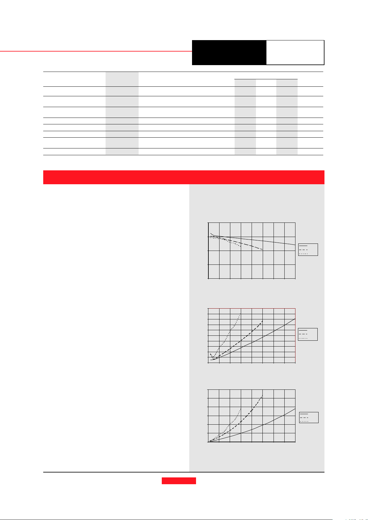
Note 1:Note 1:
Note 1:Note 1:
Note 1: All data listed in the above graphs has been developed from actual products tested at 25°C. This data is considered typical data for the ISR.
PT6670 Series (@ Vin=+3.3V) (See Note 1)
Efficiency vs Output Current
Ripple vs Output Current
Power Dissipation vs Output Current
Efficiency - %
Ripple-(mV)PD-(Watts)
Iout-(Amps)
Iout-(Amps)
Iout-(Amps)
PT6670 Series
Preliminary Specifications (continued)
Characteristics
PT6670 SERIES
(Ta = 25°C unless noted) Symbols Conditions Min Typ Max Units
Switching Frequency ƒ
o
3.0V ≤ V
in
≤ 3.6V
—
300
—
kHz
0.1A ≤ I
o
≤ I
omax
Absolute Maximum T
a
-40 — +85 °C
Operating Temperature Range
Recommended Operating T
a
Free Air Convection (40-60 LFM)
-40 — +65 °C
Temperature Range Over V
in
and Io ranges with heat tab
Thermal Resistance θ
ja
Free Air Convection (40-60 LFM) — TBD — °C/W
Storage Temperature T
s
— -40 — +125 °C
Mechanical Shock — Per Mil-STD-883D, Method 2002.3 — 500 — G’s
Mechanical Vibration — Per Mil-STD-883D, Method 2007.2,
— 7.5 — G’s
20-2000 Hz, soldered in a PC board
Weight — — — 14 — grams
Note: The PT6670 Series requires two 560µF electrolytic capacitors (input and output) for proper operation in all applications. Please note that this product does not include short circuit protection.
60
70
80
90
100
0.0 0.5 1.0 1.5 2.0 2.5 3.0 3.5 4.0
PT6671
PT6672
PT6673
0
20
40
60
80
100
120
140
160
180
200
0.0 0.5 1.0 1.5 2.0 2.5 3.0 3.5 4.0
PT6671
PT6672
PT6673
0
1
2
3
4
5
6
0.0 0. 5 1.0 1.5 2.0 2.5 3.0 3.5 4.0
PT6671
PT6672
PT6673
 Loading...