


Texas Instruments PT6624M, PT6624P, PT6624Q, PT6624R, PT6622R Datasheet
...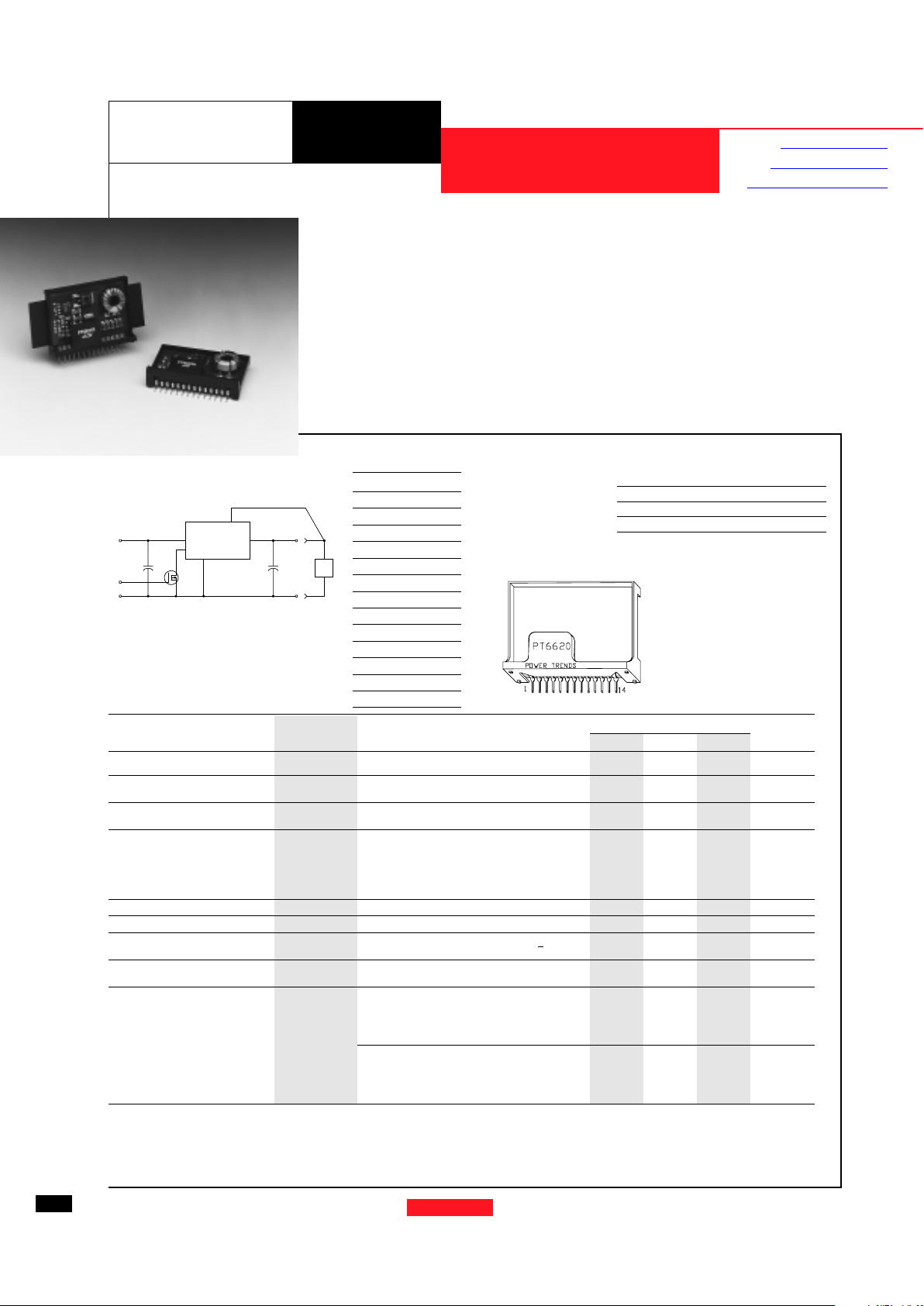
Standard Application
C1 = Required 330µF electrolytic
C2 = Required 330µF electrolytic
Q1= NFET-or Open Collector Gate
6 AMP 12V INPUT
INTEGRATED SWITCHING REGULATOR
PT6620 Series
PT6620
4,5,6
7,8,9,10
11,12,13
V
IN
COM
COM
V
OUT
C
2
+
C
1
+
1
3
STBY
Q
1
REMOTE SENSE
LOAD
Ordering Information
PT6621¨ = +3.3 Volts
PT6622¨ = +1.5 Volts
PT6623¨ = +2.5 Volts
PT6624¨ = +3.6 Volts
PT6625¨ = +5.0 Volts
PT6626¨ = +9.0 Volts
• Single Device: 6A Output
• Input Voltage Range: 9V to 14V
• Adjustable Output Voltage
• 83% Efficiency
• Remote Sense Capability
• Standby Function
• Over-Temperature Protection
The PT6620 series is a new addition
to Power Trends’ line of 12V bus Integrated Switching Regulators (ISRs).
Designed for stand-alone operation in
applications requiring as much as 6A of
output current, the PT6620 is packaged
in a 14-Pin SIP (Single In-line Package)
and is available in a surface-mount configuration.
Only two external capacitors are
required for proper operation. Please
note that this product does not include
short circuit protection.
PT Series Suffix
(PT1234X)
Case/Pin Heat Heat Spreader
Configuration Spreader with Side Tabs
Vertical Through-Hole
PR
Horizontal Through-Hole
DG
Horizontal Surface Mount
EB
Pin Function
1 Remote Sense
2 Do Not Connect
3 STBY*- Standby
4V
in
5V
in
6V
in
7 GND
8 GND
9 GND
10 GND
11 V
out
12 V
out
13 V
out
14 V
out
Adjust
Pin-Out Information
For assistance or to order, call (800) 531-5782
48
Power Trends, Inc. 27715 Diehl Road, Warrenville, IL 60555 (800) 531-5782 Fax: (630) 393-6902 http://www.powertrends.com
Note: Back surface
of product is
conducting metal
Pkg Style 400
Specifications
Characteristics
PT6620 SERIES
(Ta = 25°C unless noted) Symbols Conditions Min Typ Max Units
Output Current I
o
Ta = 60°C, 200 LFM, pkg P 0.1* — 6.0** A
Ta = 25°C, natural convection 0.1* — 6.5** A
Input Voltage Range V
in
0.1A ≤ I
o
≤ 6.0A V
o
≤ +5V +9 — +14 V
+6V≤Vo≤+9V Vo+3 — +14 V
Output Voltage Tolerance ∆V
o
V
in
= +12V, Io = 6.0A
Ta = 0 to 60°C
V
o-0.1 — Vo+0.1 V
Output Voltage Adjust Range V
oadj
Pin 14 to V
o
or ground Vo = +3.3V 2.3 — 4.5
V
o
= +1.5V 1.4 — 2.7
V
o
= +2.5V 1.9 — 3.7 V
V
o
= +3.6V 2.5 — 4.8
V
o
= +5.0V 2.9 — 6.5
V
o
= +9.0V 5.2 — 10.0
Line Regulation Reg
line
+9V≤Vin≤+14V, Io = 6.0A — ±0.5 ±1.0 %V
o
Load Regulation Reg
load
Vin = +12V, 0.1≤ Io≤6.0A — ±0.5 ±1.0 %V
o
Vo Ripple/Noise V
n
V
in
= +12V, Io = 6.0A Vo < +6V — 50 — mVpp
V
o
> +6V — 1.0 — %V
o
Transient Response t
tr
Io step between 3.0A and 6.0A — 100 — µSec
with C2 = 330µF V
os
Vo over/undershoot — 150 — mV
Efficiency η V
in
= +12V, Io = 3.0A V
o
= +3.3/3.6V — 84 — %
V
o
= +1.5V — 68 — %
V
o
= +2.5V — 76 — %
V
o
= +5.0V — 86 — %
V
o
= +9.0V — 93 — %
V
in
= +12V, Io =6.0A V
o
= +3.3/3.6V — 83 — %
V
o
= +1.5V — 66 — %
V
o
= +2.5V — 75 — %
V
o
= +5.0V — 85 — %
V
o
= +9.0V — 92 — %
* ISR will operate down to no load with reduced specifications.
** See SOA curves - Output power is limited to 30W maximum.
Note:
The PT6620 Series requires a 330µF(output) and 330µF(input) electrolytic capacitors for proper operation in all applications.
Revised 2/5/99
Application Notes
Mechanical Outline
Product Selector Guide
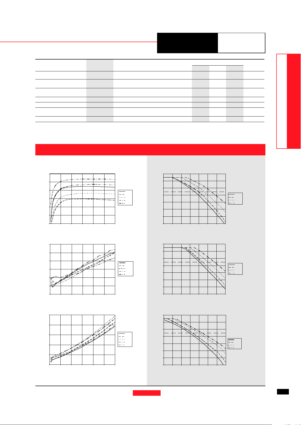
CHARACTERISTIC DATA
PT6620 Series
For assistance or to order, call (800) 531-5782
49
12V Bus Products
DATA SHEETS
Power Trends, Inc. 27715 Diehl Road, Warrenville, IL 60555 (800) 531-5782 Fax: (630) 393-6902 http://www.powertrends.com
PT6621P, 3.3V
Note: SOA curves represent operating conditions at which internal components are at or below manufacturer’s maximum rated operating temperatures.
Efficiency vs Output Current
Efficiency (%)
Output Current (A)
Ambient Temperature (°C)
Output Current (A)
Airflow
Recommended Maximum
Operating Temperature
Ambient Temperature (°C)
Output Current (A)
Airflow
PT6620 Series @VPT6620 Series @V
PT6620 Series @VPT6620 Series @V
PT6620 Series @V
in=+12Vin=+12V
in=+12Vin=+12V
in=+12V
Recommended Maximum
Operating Temperature
Specifications (continued)
Characteristics
PT6620 SERIES
(Ta = 25°C unless noted) Symbols Conditions Min Typ Max Units
Switching Frequency ƒ
o
9V ≤ V
in
≤ 14V 500 650 775 kHz
0.1A ≤ I
o
≤ 6.0A PT6622 500 550 600 kHz
Recommended Operating T
a
Free Air Convection (40-60 LFM)
-40 — +65** °C
Temperature Range Over V
in
and Io ranges with heat tab
Absolute Maximum T
a
-40 — +85 °C
Operating Temperature Range
Storage Temperature T
s
— -40 — +125 °C
Mechanical Shock — Per Mil-STD-883D, Method 2002.3 — 500 — G’s
Mechanical Vibration — Per Mil-STD-883D, Method 2007.2,
— 7.5 — G’s
20-2000 Hz, soldered in a PC board
Weight — — — 14 — grams
** See SOA curves - Output power is limited to 30W maximum.
Note: The PT6620 Series requires a 330µF(output) and 100µF(input) electrolytic capacitors for proper operation in all applications.
PT6622P, 1.5VOutput Ripple vs Output Current
Power Dissipation vs Output Current
Output Current (A)
Output Current (A)
Ripple (mVpp)
Pd (Watts)
Safe Operating Area Curves @VSafe Operating Area Curves @V
Safe Operating Area Curves @VSafe Operating Area Curves @V
Safe Operating Area Curves @V
in=+12Vin=+12V
in=+12Vin=+12V
in=+12V
20
30
40
50
60
70
80
90
01234567
Nat conv
60LFM
120LFM
200LFM
20
30
40
50
60
70
80
90
012345 67
Nat conv
60LFM
120LFM
200LFM
Ambient Temperature (°C)
Output Current (A)
Airflow
Recommended Maximum
Operating Temperature
PT6625P, 5.0V
20
30
40
50
60
70
80
90
01234567
Nat conv
60LFM
120LFM
200LFM
40
50
60
70
80
90
100
0123456
PT6621
PT6622
PT6623
PT6625
PT6626
0
5
10
15
20
25
30
0123456
PT6621
PT6622
PT6623
PT6625
PT6626
0
1
2
3
4
5
0123456
PT6621
PT6622
PT6623
PT6625
PT6626