

LMH0036
www.ti.com
SNLS254B –MARCH 2008–REVISED APRIL 2013
LMH0036 SD SDI Reclocker with 4:1 Input Multiplexer
Check for Samples: LMH0036
1
FEATURES
2
• Supports SMPTE 259M (C) Serial Digital Video
Standard
• Supports 270 Mbps Serial Data Rate Operation
• Supports DVB-ASI at 270 Mbps Equipment
• Single 3.3V Supply Operation – DVB-ASI Equipment
• 360 mW Typical Power Consumption – Video Standards and Format Converters
• Integrated 4:1 Multiplexed Input
• Two Differential, Reclocked Outputs
• Choice of Second Reclocked Output or LowJitter, Differential, Data-Rate Clock Output
• Single 27 MHz External Crystal or Reference
Clock Input
• Lock Detect Indicator Output
• Output Mute Function for Data and Clock
• Auto/Manual Reclocker Bypass
• Differential LVPECL Compatible Serial Data
Inputs and Outputs
• LVCMOS Control Inputs and Indicator Outputs
• 48-Pin WQFN Package
• Industrial Temperature Range: -40°C to +85°C
• Footprint Compatible with the LMH0056 and
LMH0356
APPLICATIONS
• SDTV Serial Digital Video Interfaces for:
– Digital Video Routers and Switchers
– Digital Video Processing and Editing
DESCRIPTION
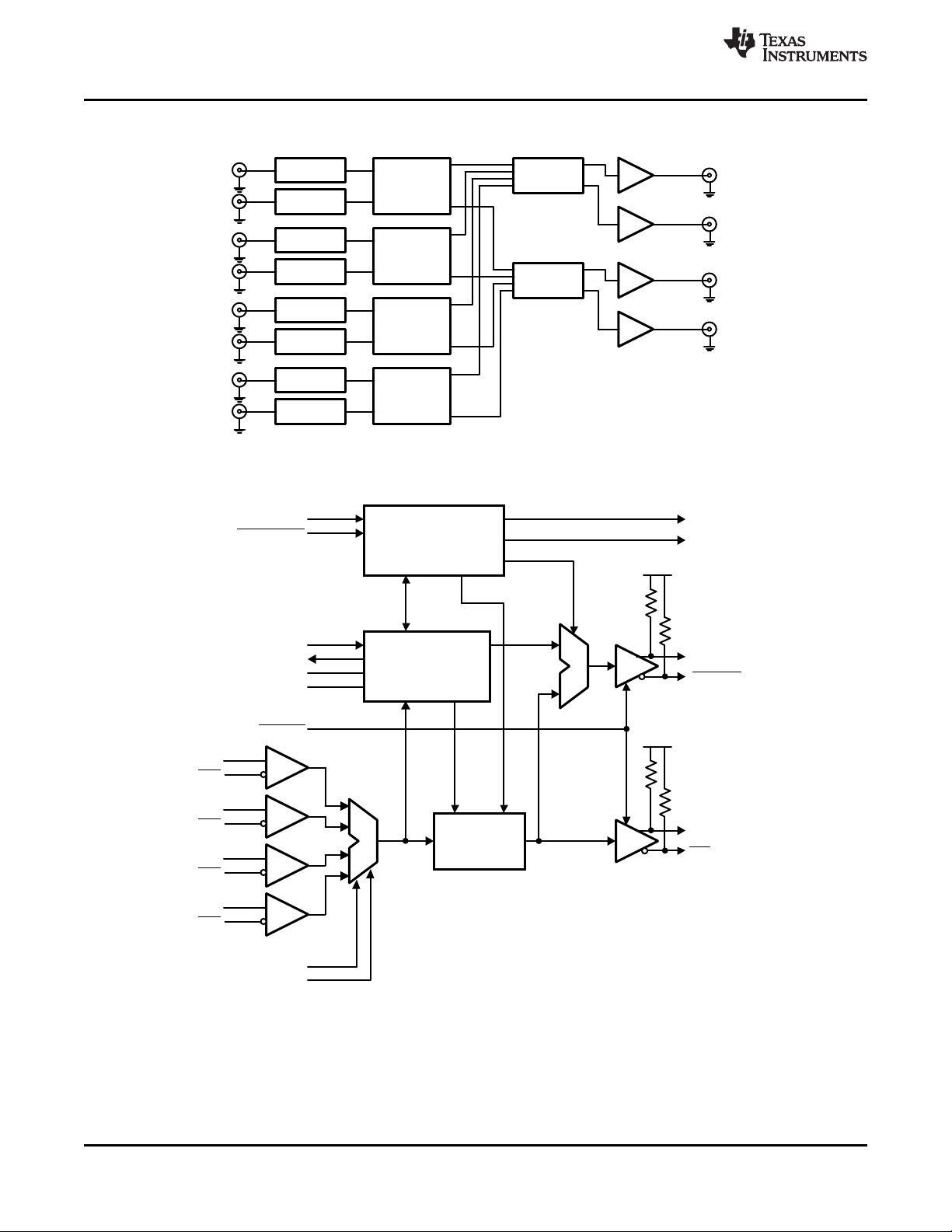
The LMH0036 SD SDI Reclocker with 4:1 Input
Multiplexer retimes serial digital video data
conforming to the SMPTE 259M (C) standard. The
LMH0036 operates at the serial data rate of 270
Mbps, and also supports DVB-ASI operation at 270
Mbps. The LMH0036 includes an integrated 4:1 input
multiplexer for selecting one of four input data
streams for retiming.
The LMH0036 retimes the incoming data to suppress
accumulated jitter. The LMH0036 recovers the serial
data-rate clock and optionally provides it as an
output. The LMH0036 has two differential serial data
outputs; the second output may be selected as a lowjitter, data-rate clock output. Controls and indicators
are: serial clock or second serial data output select,
manual rate select input, SD indicator output, lock
detect output, auto/manual data bypass, and output
mute. The serial data inputs, outputs, and serial datarate clock outputs are differential LVPECL
compatible. The CML serial data and serial data-rate
clock outputs are suitable for driving 100Ω
differentially terminated networks. The control logic
inputs and outputs are LVCMOS compatible.
The LMH0036 is powered from a single 3.3V supply.
Power dissipation is typically 360 mW. The device is
housed in a 48-pin WQFN package.
1
Please be aware that an important notice concerning availability, standard warranty, and use in critical applications of
Texas Instruments semiconductor products and disclaimers thereto appears at the end of this data sheet.
2All trademarks are the property of their respective owners.
PRODUCTION DATA information is current as of publication date.
Products conform to specifications per the terms of the Texas
Instruments standard warranty. Production processing does not
necessarily include testing of all parameters.
Copyright © 2008–2013, Texas Instruments Incorporated
RETIMER/FIFO
VCO/PLL
SDI0
LOCK DETECT
SDO
CONTROL LOGIC
AUTO BYPASS
BYPASS/
O/P MUTE
50
50
XTAL IN/EXT CLK
XTAL OUT
LOOP FILTER 1
LOOP FILTER 2
SCO_EN
SCO/SDO2
BYPASS
SDI0
SDO
50
50
V
CCO
V
CCO
SCO/SDO2
SDI1
SDI1
SDI2
SDI2
SDI3
SDI3
SEL0
SEL1
SD
LMH0074
Equalizer
Crosspoint
LMH0036
Reclocker
LMH0036
Reclocker
LMH0001
Cable Driver
LMH0074
Equalizer
LMH0074
Equalizer
LMH0074
Equalizer
LMH0074
Equalizer
LMH0074
Equalizer
LMH0074
Equalizer
LMH0074
Equalizer
LMH0001
Cable Driver
LMH0001
Cable Driver
LMH0001
Cable Driver
Crosspoint
Crosspoint
Crosspoint
LMH0036
SNLS254B –MARCH 2008–REVISED APRIL 2013
Typical Application
Block Diagram
www.ti.com
2 Submit Documentation Feedback Copyright © 2008–2013, Texas Instruments Incorporated
Product Folder Links: LMH0036
1
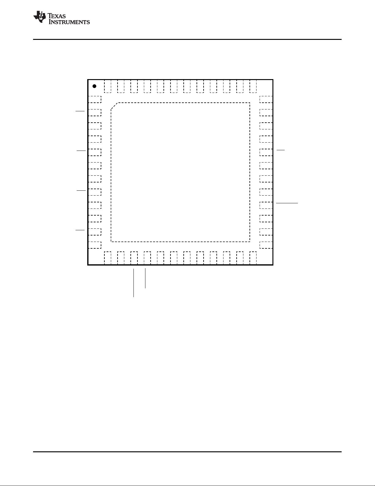
LMH0036
(top view)
V
CC
SDI0
SDI0
SCO/SDO2
SCO/SDO2
V
CC
XTAL IN/
EXT CLK
V
EE
V
CC
SDI1
SDI1
V
CC
SDI2
SDI2
SDI3
SDI3
2
3
4
5
6
7
8
9
10
11
12
13 14 15 16 17 18 19 20 21 22 23 24
36
35
34
33
32
31
30
29
28
27
26
25
48 47 46 45 44 43 42 41 40 39 38 37
SDO
SDO
V
EE
V
CC
V
EE
LF1
SEL1
SEL0
LF2
V
EE
SCO_EN
V
EE
V
CC
V
CC
V
EE
V
EE
V
CC
V
CC
O/P MUTE
XTAL OUT
VEEV
EE
V
EE
LOCK DET
V
EE
SD
RSVD
NC
V
EE
V
EE
V
EE
BYPASS/
AUTOBYPASS
LMH0036
www.ti.com
Connection Diagram
SNLS254B –MARCH 2008–REVISED APRIL 2013
The exposed die attach pad is the primary negative electrical terminal for this device. It must be connected to the
negative power supply voltage.
See Package Number RHS0048A
Figure 1. 48-Pin WQFN
Copyright © 2008–2013, Texas Instruments Incorporated Submit Documentation Feedback 3
Product Folder Links: LMH0036
LMH0036
SNLS254B –MARCH 2008–REVISED APRIL 2013
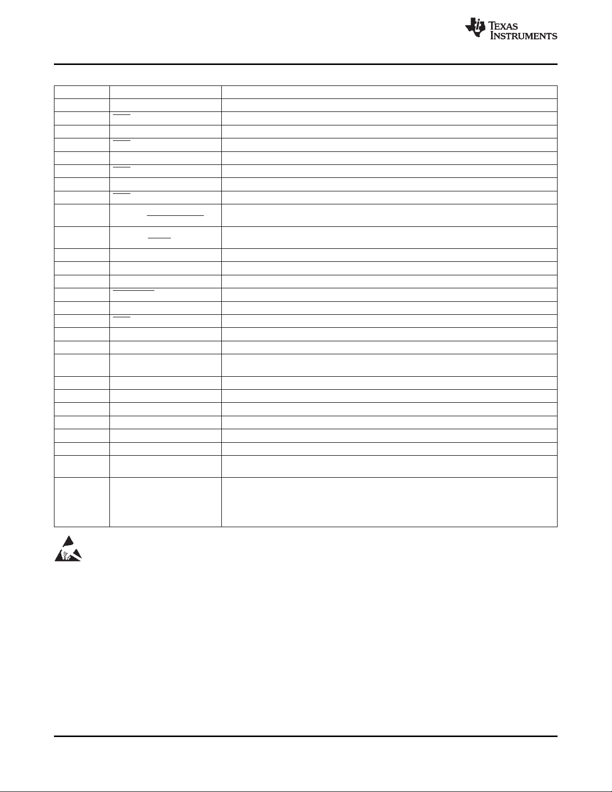
PIN DESCRIPTIONS
Pin Name Description
1 SDI0 Data Input 0 True.
2 SDI0 Data Input 0 Complement.
4 SDI1 Data Input 1 True.
5 SDI1 Data Input 1 Complement
7 SDI2 Data Input 2 True.
8 SDI2 Data Input 2 Complement.
10 SDI3 Data Input 3 True.
11 SDI3 Data Input 3 Complement.
15 BYPASS/AUTO BYPASS pulldown.
16 OUTPUT MUTE pullup.
18 XTAL IN/EXT CLK Crystal or External Oscillator input.
22 XTAL OUT Crystal Oscillator output.
24 LOCK DETECT PLL Lock Detect output (active high).
28 SCO/SDO2 Serial Clock or Serial Data Output 2 complement.
29 SCO/SDO2 Serial Clock or Serial Data Output 2 true.
32 SDO Data Output complement.
33 SDO Data Output true.
36 SD SD indicator output. Output is high when locked to 270 Mbps.
37 SCO_EN high and the data when low. This pin has an internal pulldown.
43 LF1 Loop Filter.
44 LF2 Loop Filter.
45 NC No Connect. Not bonded internally.
46 RSVD Reserved. Do not connect or connect to ground.
47 SEL0 Data Input select input. This pin has an internal pulldown.
48 SEL1 Data Input select input. This pin has an internal pulldown.
3, 6, 12, 14,
30, 31, 34, 35 V
DAP, 13, 17,
19, 20, 21,
23, 25, 26,
27, 38, 39,
40, 41, 42 V
CC
EE
Bypass/Auto Bypass mode select. Bypasses reclocking when high. This pin has an internal
Data and Clock Output Mute input. Mutes the output when low. This pin has an internal
Serial Clock or Serial Data 2 Output select. Sets second output to output the clock when
Positive power supply input.
Negative power supply input.
www.ti.com
These devices have limited built-in ESD protection. The leads should be shorted together or the device placed in conductive foam
during storage or handling to prevent electrostatic damage to the MOS gates.
4 Submit Documentation Feedback Copyright © 2008–2013, Texas Instruments Incorporated
Product Folder Links: LMH0036

LMH0036
www.ti.com
ABSOLUTE MAXIMUM RATINGS
(1)(2)
SNLS254B –MARCH 2008–REVISED APRIL 2013
Supply Voltage (VCC–VEE) 4.0V
Logic Supply Voltage (Vi) VEE−0.15V to VCC+0.15V
Logic Input Current (single input) Vi = VEE−0.15V −5 mA
Vi = VCC+0.15V +5 mA
Logic Output Voltage (Vo) VEE−0.15V to VCC+0.15V
Logic Output Source/Sink Current ±8 mA
Serial Data Input Voltage (V
Serial Data Output Sink Current (I
) VCCto VCC−2.0V
SDI
) 24 mA
SDO
Package Thermal Resistance θJA48-pin WQFN 26.1°C/W
θ
48-pin WQFN 1.9°C/W
JC
Storage Temp. Range −65°C to +150°C
Junction Temperature +150°C
Lead Temperature (Soldering 4 Sec) +260°C (Pb-free)
ESD Rating (HBM) 8 kV
ESD Rating (MM) 400V
ESD Rating (CDM) 1250V
(1) “Absolute Maximum Ratings” are those parameter values beyond which the life and operation of the device cannot be ensured. The
stating herein of these maximums shall not be construed to imply that the device can or should be operated at or beyond these values.
DC ELECTRICAL CHARACTERISTICS and AC ELECTRICAL CHARACTERISTICS specify acceptable device operating conditions.
(2) It is anticipated that this device will not be offered in a military qualified version. If Military/Aerospace specified devices are
required, please contact the Texas Instruments Sales Office/Distributors for availability and specifications.
RECOMMENDED OPERATING CONDITIONS
Supply Voltage (VCC–VEE) 3.3V ±5%
Logic Input Voltage VEEto V
Differential Serial Input Voltage 800 mV ±10%
Serial Data or Clock Output Sink Current (ISO) 16 mA max.
Operating Free Air Temperature (TA) −40°C to +85°C
DC ELECTRICAL CHARACTERISTICS
Over Supply Voltage and Operating Temperature ranges, unless otherwise specified.
Symbol Parameter Conditions Reference Min Typ Max Units
V
V
V
V
V
SDID
V
V
SDOD
V
CMO
I
(1) Current flow into device pins is defined as positive. Current flow out of device pins is defined as negative. All voltages are referenced to
VEE(equal to zero volts).
(2) Typical values are stated for: VCC= +3.3V, TA= +25°C.
Input Voltage High Level Logic level inputs 2 V
IH
Input Voltage Low Level V
IL
I
Input Current High Level VIH= V
IH
I
Input Current Low Level VIL= V
IL
Output Voltage High Level IOH= −2 mA All logic level 2 V
OH
Output Voltage Low Level IOL= +2 mA VEE+ 0.6 V
OL
CC
EE
outputs
Serial Input Voltage, SDI
Differential
Input Common Mode V
CMI
Voltage
= 200 mV SDI
SDID
Serial Output Voltage, 100Ω differential load SDO, SCO
Differential
Output Common Mode 100Ω differential load SDO, SCO V
Voltage
Power Supply Current, 270 Mbps, NTSC color bar
CC
3.3V supply, Total pattern
(1)(2)
CC
EE
0.8 V
47 65 µA
−18 −25 µA
200 1600 mV
VEE+1.2 VCC−0.2 V
720 800 880 mV
−
CC
V
SDOD
109 mA
V
P-P
P-P
V
CC
Copyright © 2008–2013, Texas Instruments Incorporated Submit Documentation Feedback 5
Product Folder Links: LMH0036
LMH0036
SNLS254B –MARCH 2008–REVISED APRIL 2013
www.ti.com
AC ELECTRICAL CHARACTERISTICS
Over Supply Voltage and Operating Temperature ranges, unless otherwise specified.
Symbol Parameter Conditions Reference Min Typ Max Units
BR
TOL
TOL
t
BW
F
t
T
tr, t
tr, t
tr, t
tr, t
F
F
Serial Data Rate SMPTE 259M (C) SDI, SDO 270 Mbps
SD
Serial Input Jitter 270 Mbps
JIT
Tolerance
Serial Input Jitter 270 Mbps
JIT
Tolerance
Serial Data Output Jitter 270 Mbps
JIT
Loop Bandwidth 270 Mbps,
LOOP
Serial Clock Output 270 Mbps data rate SCO
CO
Frequency
Serial Clock Output Jitter 2 3 ps
JIT
<0.1dB Peaking
(2)(3)(4)
(2)(3)(5)
(3)(6)
SDI
SDI
SDO 0.02 0.08 UI
Serial Clock Output SDO, SCO
Alignment with respect to 40 60 %
Data Interval
Serial Clock Output Duty SCO
Cycle
Acquisition Time See
ACQ
Input rise/fall time 10%–90% Logic inputs 1.5 3 ns
f
Input rise/fall time 20%–80% SDI 1500 ps
f
Output rise/fall time 10%–90% Logic outputs 1.5 3 ns
f
Output rise/fall time 20%–80%
f
Reference Clock
REF
Frequency
Ref. Clock Freq.
TOL
Tolerance
(7)(8)
(9)
SCO, SDO 90 130 ps
(1)
>6 UI
>0.6 UI
300 kHz
270 MHz
45 55 %
15 ms
27 MHz
±50 ppm
P-P
P-P
P-P
RMS
(1) Typical values are stated for: VCC= +3.3V, TA= +25°C.
(2) Peak-to-peak amplitude with sinusoidal modulation per SMPTE RP 184-1996 paragraph 4.1. The test data signal shall be color bars.
(3) This parameter is ensured by characterization over voltage and temperature limits.
(4) Refer to “A1” in Figure 1 of SMPTE RP 184-1996.
(5) Refer to “A2” in Figure 1 of SMPTE RP 184-1996.
(6) Serial Data Output Jitter is total output jitter with 0.2UI
(7) Specification is ensured by design.
input jitter.
P-P
(8) Measured from first SDI transition until Lock Detect (LD) output goes high (true).
(9) RL= 100Ω differential.
6 Submit Documentation Feedback Copyright © 2008–2013, Texas Instruments Incorporated
Product Folder Links: LMH0036

LMH0036
www.ti.com
SNLS254B –MARCH 2008–REVISED APRIL 2013
DEVICE DESCRIPTION
The LMH0036 SD SDI Reclocker with 4:1 Input Multiplexer is used in many types of digital video signal
processing equipment. The LMH0036 supports the SMPTE 259M (C) standard, with a corresponding serial data
rate of 270 Mbps. DVB-ASI data at 270 Mbps may also be retimed. The LMH0036 retimes the serial data stream
to suppress accumulated jitter. It provides two low-jitter, differential, serial data outputs. The second output may
be selected to output either serial data or a low-jitter serial data-rate clock. Controls and indicators are: serial
data-rate clock or second serial data output select, manual rate select input, SD indicator output, lock detect
output, auto/manual data bypass and output mute.
Serial data inputs are CML and LVPECL compatible. Serial data and data-rate clock outputs are differential CML
and produce LVPECL compatible levels. The output buffer design can drive AC or DC-coupled, terminated 100Ω
differential loads. The differential output level is 800 mV
±10% into 100Ω AC or DC-coupled differential loads.
P-P
Logic inputs and outputs are LVCMOS compatible.
The device package is a 48–pin WQFN with an exposed die attach pad. The exposed die attach pad is
electrically connected to device ground (VEE) and is the primary negative electrical terminal for the device. This
terminal must be connected to the negative power supply or circuit ground.
Serial Data Inputs, Serial Data and Clock Outputs
SERIAL DATA INPUT AND OUTPUTS
The differential serial data inputs, SDI0-SDI3, accept 270 Mbps serial digital video data. The serial data inputs
are differential LVPECL compatible. These inputs are intended to be DC interfaced to devices such as the
LMH0074 adaptive cable equalizer. These inputs are not internally terminated or biased. The inputs may be ACcoupled if a suitable input bias voltage is provided.
The LMH0036 provides four independent, multiplexed data inputs. The active input channel is selected via the
SEL0 and SEL1 pins, as shown in Table 1. Figure 2 shows the equivalent input circuit for SDI[3:0] and SDI[3:0].
The LMH0036 has two, retimed, differential, serial data outputs, SDO and SCO/SDO2. These outputs provide
low jitter, differential, retimed data to devices such as the LMH0001 or LMH0002 cable driver. Output SCO/SDO2
is multiplexed and can provide either a second serial data output or a serial data-rate clock output. Figure 3
shows the equivalent output circuit for SDO, SDO, SCO/SDO2, and SCO/SDO2.
The SCO_EN input controls the operating mode for the SCO/SDO2 output. When the SCO_EN input is high the
SCO/SDO2 output provides a serial data-rate clock. When SCO_EN is low, the SCO/SDO2 output provides
retimed serial data.
Both differential serial data outputs, SDO and SCO/SDO2, are muted when the OUTPUT MUTE input is a logic
low level. SCO/SDO2 also mutes when the Bypass mode is activated when this output is operating as the serial
clock output. When muted, SDO and SDO (or SDO2 and SDO2) will assume opposite differential output levels.
The CML serial data outputs are differential LVPECL compatible. These outputs have internal 50Ω pull-ups and
are suitable for driving AC or DC-coupled, 100Ω center-tapped, AC grounded or 100Ω un-center-tapped,
differentially terminated networks.
Copyright © 2008–2013, Texas Instruments Incorporated Submit Documentation Feedback 7
Product Folder Links: LMH0036

50:
SDO, SCO/SDO2
V
CC
V
CC
50:
V
CC
SDO, SCO/SDO2
SDI[3:0]
V
CC
V
CC
SDI[3:0]
2 k:
80 k:
1 pF
20 k:
V
CC
2 k:
LMH0036
SNLS254B –MARCH 2008–REVISED APRIL 2013
Figure 2. Equivalent SDI Input Circuit (SDI[3:0], SDI[3:0])
www.ti.com
Figure 3. Equivalent SDO Output Circuit (SDO, SDO, SCO/SDO2, SCO/SDO2)
SERIAL DATA CLOCK/SERIAL DATA 2 OUTPUT
The Serial Data Clock/Serial Data 2 Output is controlled by the SCO_EN input and provides either a second
retimed serial data output or a low jitter differential clock output appropriate to the serial data rate being
processed. When operating as a serial clock output, the rising edge of the clock will be positioned within the
corresponding serial data bit interval within 10% of the center of the data interval.
Differential output SCO/SDO2 functions as the second serial data output when the SCO_EN input is a logic-low
level. This output functions as the serial data-rate clock output when the SCO_EN input is a logic-high level. The
SCO_EN input has an internal pull-down device and the default state of SCO_EN is low (serial data output 2
enabled). SCO/SDO2 is muted when the OUTPUT MUTE input is a logic low level. When the Bypass mode is
activated and this output is functioning as a serial clock output, the output will also be muted. If an unsupported
data rate is used while in Auto Bypass mode with this output functioning as a serial clock output, the output is
invalid.
8 Submit Documentation Feedback Copyright © 2008–2013, Texas Instruments Incorporated
Product Folder Links: LMH0036

LMH0036
www.ti.com
SNLS254B –MARCH 2008–REVISED APRIL 2013
Control Inputs and Indicator Outputs
SERIAL DATA INPUT SELECTOR
The Serial Data Input Selector (SEL [1:0]) allows the user to select the active input channel. Table 1 shows the
input selected for a given state of SEL [1:0].
Table 1. Data Input Select Codes
SEL [1:0] Code Selected Input
00 SDI0
01 SDI1
10 SDI2
11 SDI3
LOCK DETECT
The Lock Detect (LD) output, when high, indicates that data is being received and the PLL is locked. LD may be
connected to the OUTPUT MUTE input to mute the data and clock outputs when no data signal is being
received. Note that when the Bypass/Auto Bypass input is set high, Lock Detect will remain low. See Table 2.
OUTPUT MUTE
The OUTPUT MUTE input, when low, mutes the serial data and clock outputs. It may be connected to Lock
Detect or externally driven to mute or un-mute the outputs. If OUTPUT MUTE is connected to LD, then the data
and clock outputs are muted when the PLL is not locked. This function overrides the Bypass function: see
Table 2. OUTPUT MUTE has an internal pull-up device to enable the output by default.
BYPASS/AUTO BYPASS
The Bypass/Auto Bypass input, when high, forces the device to output the data without reclocking it. When this
input is low, the device automatically bypasses the reclocking function when the device is in an unlocked
condition or the detected data rate is a rate which the device does not support. Note that when the Bypass/Auto
Bypass input is set high, Lock Detect will remain low. See Table 2. BYPASS/AUTO BYPASS has an internal pulldown device.
Table 2. Control Functionality
LOCK DETECT OUTPUT MUTE BYPASS/AUTO BYPASS DEVICE STATUS
0 1 X PLL unlocked, reclocker bypassed
1 1 0 PLL locked to supported data rate, reclocker not bypassed
X 0 X Outputs muted
0 LOCK DETECT X Outputs muted
1 LOCK DETECT 0 PLL locked to supported data rate, reclocker not bypassed
SD
The SD output indicates that the LMH0036 is locked and processing SD data rates. It may be used to control
another device such as the LMH0002 cable driver. When this output is high it indicates that the data rate is 270
Mbps. The SD output is a registered function and is only valid when the PLL is locked and the Lock Detect
output is high. The SD output is undefined for a short time after lock detect assertion or de-assertion due to a
data change on the SDI input. See Figure 4 for a timing diagram showing the relationship between SDI, Lock
Detect, and SD.
Copyright © 2008–2013, Texas Instruments Incorporated Submit Documentation Feedback 9
Product Folder Links: LMH0036

SDI 270 MBPS DATANO DATA
Lock
Detect
SD
T
2
NO DATA 270 MBPS DATA NO DATA
T
2
T
ACQ
= Acquisition Time, defined in the AC Electrical Characteristics Table
T1 = Time from Lock Detect assertion or deassertion until SD output is valid, typically 37ns (one 27 MHz clock period)
T2 = Time from SDI input change until Lock Detect de-assertion, 1 ms maximum. SD output is not valid during this time.
T
ACQ
T
1
T
1
T
ACQ
T
1
T
1
LMH0036
SNLS254B –MARCH 2008–REVISED APRIL 2013
www.ti.com
Figure 4. SDI, Lock Detect, and SD Timing
SCO_EN
Input SCO_EN enables the SCO/SDO2 differential output to function either as a serial data-rate clock or second
serial data output. SCO/SDO2 functions as a serial data-rate clock when SCO_EN is high. This pin has an
internal pull-down device. The default state (low) enables the SCO/SDO2 output as a second serial data output.
CRYSTAL OR EXTERNAL CLOCK REFERENCE
The LMH0036 uses a 27 MHz crystal or external clock signal as a timing reference input. A 27 MHz parallel
resonant crystal and load network may be connected to the XTAL IN/EXT CLK and XTAL OUT pins.
Alternatively, a 27 MHz LVCMOS compatible clock signal may be input to XTAL IN/EXT CLK. Parameters for a
suitable crystal are given in Table 3.
Frequency 27 MHz
Frequency Stability ±100 ppm @ recommended drive level
Operating Mode Fundamental mode, Parallel Resonant
Load Capacitance 20 pF
Shunt Capacitance 7 pF
Series Resistance 40Ω max.
Recommended Drive Level 100 µW
Maximum Drive Level 500 µW
Operating Temperature Range −10°C to +60°C
Table 3. Crystal Parameters
Parameter Value
10 Submit Documentation Feedback Copyright © 2008–2013, Texas Instruments Incorporated
Product Folder Links: LMH0036

LMH0036
SDI0
SDI0
1
2
3
4
5
6
7
8
9
10
11
12
SCO_EN
25
26
27
28
29
30
31
32
33
34
SCO/SDO2
SCO/SDO2
SDO
SDO
SD
131415161718192021
22
V
CC
SDI1
SDI1
V
CC
SDI2
SDI2
SDI3
SDI3
V
EE
V
CC
V
CC
OP MUTE
XTAL IN
BP/
AUTO-BP
VEEVEEVEEV
EE
XTAL OUT
LOCK DET
23
24
V
EE
V
EE
V
EE
V
EE
35
36
V
CC
V
CC
V
CC
V
CC
37
38
39
40
41
42
43
44
45
46
47
48
DAP
VEEVEEVEEVEEV
EE
SEL1
SEL0
RSVD
NC
LF2
LF1
100:
Differential
Data Input 3
V
CC
100:
Differential
Data Input 2
100:
Differential
Data Input 1
100:
Differential
Data Input 0
V
CC
27 MHz
39 pF 39 pF
Data
Output
Clock Output or
2nd Data Output
V
CC
56 nF
LOCK DET
OP MUTE
BP/
AUTO-BP
SEL1
SEL0
SCO_EN
SD
V
CC
LMH0036
www.ti.com
APPLICATION INFORMATION
Figure 5 shows a application circuit for the LMH0036.
SNLS254B –MARCH 2008–REVISED APRIL 2013
BYPASS/AUTO BYPASS has an internal pulldown to enable Auto Bypass mode by default. This pin may be
pulled high to force the LMH0036 to bypass all data.
OUTPUT MUTE has an internal pullup to enable the outputs by default. This pin may be pulled low to mute the
outputs.
The XTAL IN/EXT CLK and XTAL OUT pins are shown with a 27 MHz crystal and the proper loading. The crystal
should match the parameters described in Table 3. Alternately, a 27MHz LVCMOS compatible clock signal may
be input to XTAL IN/EXT CLK.
The active high LOCK DETECT output provides an indication that proper data is being received and the PLL is
locked.
The SD output may be used to drive the SD/HD pin of an SDI cable driver (such as the LMH0002) in order to
properly set the cable driver’s edge rate for SMPTE compliance. It defaults to low when the LMH0036 is not
Figure 5. Application Circuit
locked.
Copyright © 2008–2013, Texas Instruments Incorporated Submit Documentation Feedback 11
Product Folder Links: LMH0036

LMH0036
100:
SDO
SDO
75:
LMH0001
SD SDI Cable Driver
SDO
SDI
SDO
SDI
75:
75:
75:
75:
75:
+3.3V
Coaxial Cable
Coaxial Cable
4.7 PF
4.7 PF
5.6 nH
5.6 nH
SDO
SDO
LMH0036
SDI0
SDI0
LMH0074
SD SDI Cable Equalizer
Coaxial Cable
75:
37.4:
75:
6.8 nH
1.0 PF
1.0 PF
SDI
SDI
100:
LMH0036
SNLS254B –MARCH 2008–REVISED APRIL 2013
www.ti.com
SCO_EN has an internal pulldown to set the second output (SCO/SDO2) to output data. This pin may be pulled
high to set the second output as a serial clock.
The external loop filter capacitor (between LF1 and LF2) should be 56 nF. This is the only supported value; the
loop filter capacitor should not be changed.
SEL0 and SEL1 have internal pulldowns to select the SDI0 input by default.
The inputs are LVPECL compatible. The LMH0036 has a wide input common mode range and in most cases the
input should be DC coupled. For DC coupling, the inputs must be kept within the common mode range specified
in DC ELECTRICAL CHARACTERISTICS.
Figure 6 shows an example of a DC coupled interface between the LMH0074 cable equalizer and the LMH0036.
The LMH0074 output common mode voltage and voltage swing are within the range of the input common mode
voltage and voltage swing of the LMH0036. All that is required is a 100Ω differential termination as shown. The
resistor should be placed as close as possible to the LMH0036 input. If desired, this network may be terminated
with two 50Ω resisters and a center tap capacitor to ground in place of the single 100Ω resistor.
The outputs are LVPECL compatible. SDO is the primary data output and SCO/SDO2 is a second output that
may be set as the serial clock or a second data output. Both outputs are always active. The LMH0036 output
should be DC coupled to the input of the receiving device as long as the common mode ranges of both devices
are compatible.
Figure 7 shows an example of a DC coupled interface between the LMH0036 and LMH0001 cable driver. All that
is required is a 100Ω differential termination as shown. The resistor should be placed as close to the LMH0302
input as possible. If desired, this network may be terminated with two 50Ω resisters and a center tap capacitor to
ground in place of the single 100Ω resistor.
The LMH0036 has multiple ground connections, however; the primary ground connection is through the large
exposed DAP. The DAP must be connected to ground for proper operation of the LMH0036.
Figure 6. DC Input Interface
12 Submit Documentation Feedback Copyright © 2008–2013, Texas Instruments Incorporated
Figure 7. DC Output Interface
Product Folder Links: LMH0036

LMH0036
www.ti.com
SNLS254B –MARCH 2008–REVISED APRIL 2013
REVISION HISTORY
Changes from Revision A (April 2013) to Revision B Page
• Changed layout of National Data Sheet to TI format .......................................................................................................... 12
Copyright © 2008–2013, Texas Instruments Incorporated Submit Documentation Feedback 13
Product Folder Links: LMH0036

PACKAGE OPTION ADDENDUM
www.ti.com
10-Dec-2020
PACKAGING INFORMATION
Orderable Device Status
LMH0036SQE/NOPB ACTIVE WQFN RHS 48 250 RoHS & Green SN Level-3-260C-168 HR -40 to 85 XL036
(1)
The marketing status values are defined as follows:
ACTIVE: Product device recommended for new designs.
LIFEBUY: TI has announced that the device will be discontinued, and a lifetime-buy period is in effect.
NRND: Not recommended for new designs. Device is in production to support existing customers, but TI does not recommend using this part in a new design.
PREVIEW: Device has been announced but is not in production. Samples may or may not be available.
OBSOLETE: TI has discontinued the production of the device.
Package Type Package
(1)
Drawing
Pins Package
Qty
Eco Plan
(2)
Lead finish/
Ball material
(6)
MSL Peak Temp
(3)
Op Temp (°C) Device Marking
(4/5)
(2)
RoHS: TI defines "RoHS" to mean semiconductor products that are compliant with the current EU RoHS requirements for all 10 RoHS substances, including the requirement that RoHS substance
do not exceed 0.1% by weight in homogeneous materials. Where designed to be soldered at high temperatures, "RoHS" products are suitable for use in specified lead-free processes. TI may
reference these types of products as "Pb-Free".
RoHS Exempt: TI defines "RoHS Exempt" to mean products that contain lead but are compliant with EU RoHS pursuant to a specific EU RoHS exemption.
Green: TI defines "Green" to mean the content of Chlorine (Cl) and Bromine (Br) based flame retardants meet JS709B low halogen requirements of <=1000ppm threshold. Antimony trioxide based
flame retardants must also meet the <=1000ppm threshold requirement.
(3)
MSL, Peak Temp. - The Moisture Sensitivity Level rating according to the JEDEC industry standard classifications, and peak solder temperature.
(4)
There may be additional marking, which relates to the logo, the lot trace code information, or the environmental category on the device.
(5)
Multiple Device Markings will be inside parentheses. Only one Device Marking contained in parentheses and separated by a "~" will appear on a device. If a line is indented then it is a continuation
of the previous line and the two combined represent the entire Device Marking for that device.
(6)
Lead finish/Ball material - Orderable Devices may have multiple material finish options. Finish options are separated by a vertical ruled line. Lead finish/Ball material values may wrap to two
lines if the finish value exceeds the maximum column width.
Important Information and Disclaimer:The information provided on this page represents TI's knowledge and belief as of the date that it is provided. TI bases its knowledge and belief on information
provided by third parties, and makes no representation or warranty as to the accuracy of such information. Efforts are underway to better integrate information from third parties. TI has taken and
continues to take reasonable steps to provide representative and accurate information but may not have conducted destructive testing or chemical analysis on incoming materials and chemicals.
TI and TI suppliers consider certain information to be proprietary, and thus CAS numbers and other limited information may not be available for release.
In no event shall TI's liability arising out of such information exceed the total purchase price of the TI part(s) at issue in this document sold by TI to Customer on an annual basis.
Samples
Addendum-Page 1

PACKAGE MATERIALS INFORMATION
www.ti.com 20-Sep-2016
TAPE AND REEL INFORMATION
*All dimensions are nominal
Device Package
LMH0036SQE/NOPB WQFN RHS 48 250 178.0 16.4 7.3 7.3 1.3 12.0 16.0 Q1
Type
Package
Drawing
Pins SPQ Reel
Diameter
(mm)
Reel
Width
W1 (mm)
A0
(mm)B0(mm)K0(mm)P1(mm)W(mm)
Pin1
Quadrant
Pack Materials-Page 1

PACKAGE MATERIALS INFORMATION
www.ti.com 20-Sep-2016
*All dimensions are nominal
Device Package Type Package Drawing Pins SPQ Length (mm) Width (mm) Height (mm)
LMH0036SQE/NOPB WQFN RHS 48 250 210.0 185.0 35.0
Pack Materials-Page 2

PACKAGE OUTLINE
PIN 1 INDEX AREA
0.8
0.7
B
7.15
6.85
WQFN - 0.8 mm max heightRHS0048A
PLASTIC QUAD FLATPACK - NO LEAD
0.5
0.3
0.30
0.18
SCALE 1.800
A
7.15
6.85
DETAIL
OPTIONAL TERMINAL
TYPICAL
C
DIM A
OPT 1
(0.1) (0.2)
(0.2)
4214990/B 04/2018
44X 0.5
SEE TERMINAL
DETAIL
(OPTIONAL)
0.05
0.00
2X
5.5
PIN 1 ID
12
SEATING PLANE
0.08 C
2X 5.5
5.1 0.1
0.5
0.3
37
24
25
EXPOSED
THERMAL PAD
SYMM
36
0.30
48X
0.18
0.1 C A B
0.05
13
49
1
48
SYMM
48X
(A) TYP
NOTES:
1. All linear dimensions are in millimeters. Any dimensions in parenthesis are for reference only. Dimensioning and tolerancing
per ASME Y14.5M.
2. This drawing is subject to change without notice.
3. The package thermal pad must be soldered to the printed circuit board for thermal and mechanical performance.
OPT 2
www.ti.com

48X (0.6)
48X (0.25)
44X (0.5)
EXAMPLE BOARD LAYOUT
WQFN - 0.8 mm max heightRHS0048A
PLASTIC QUAD FLATPACK - NO LEAD
( 5.1)
SYMM
48
1
37
36
(1.05) TYP
SYMM
(R0.05)
TYP
( 0.2) TYP
VIA
ALL AROUND
EXPOSED
METAL
12
0.07 MAX
13
49
(1.25)
TYP
(6.8)
(1.05)
TYP
LAND PATTERN EXAMPLE
EXPOSED METAL SHOWN
SCALE:12X
ALL AROUND
METAL EDGE
SOLDER MASK
OPENING
EXPOSED
METAL
(1.25) TYP
(6.8)
25
24
0.07 MIN
SOLDER MASK
OPENING
METAL UNDER
SOLDER MASK
NON SOLDER MASK
DEFINED
(PREFERRED)
SOLDER MASK
DEFINED
SOLDER MASK DETAILS
4214990/B 04/2018
NOTES: (continued)
4. This package is designed to be soldered to a thermal pad on the board. For more information, see Texas Instruments literature
number SLUA271 (www.ti.com/lit/slua271).
5. Vias are optional depending on application, refer to device data sheet. If any vias are implemented, refer to their locations shown
on this view. It is recommended that vias under paste be filled, plugged or tented.
www.ti.com

EXAMPLE STENCIL DESIGN
WQFN - 0.8 mm max heightRHS0048A
PLASTIC QUAD FLATPACK - NO LEAD
48X (0.6)
48X (0.25)
44X (0.5)
SYMM
(R0.05) TYP
METAL
TYP
(0.625) TYP
48
1
49
(1.25)
TYP
37
36
(1.25)
TYP
(0.625) TYP
(6.8)
12
13
16X
( 1.05)
SYMM
(6.8)
24
25
SOLDER PASTE EXAMPLE
BASED ON 0.125 mm THICK STENCIL
EXPOSED PAD 49
68% PRINTED SOLDER COVERAGE BY AREA UNDER PACKAGE
NOTES: (continued)
6. Laser cutting apertures with trapezoidal walls and rounded corners may offer better paste release. IPC-7525 may have alternate
design recommendations.
SCALE:15X
4214990/B 04/2018
www.ti.com

IMPORTANT NOTICE AND DISCLAIMER
TI PROVIDES TECHNICAL AND RELIABILITY DATA (INCLUDING DATASHEETS), DESIGN RESOURCES (INCLUDING REFERENCE
DESIGNS), APPLICATION OR OTHER DESIGN ADVICE, WEB TOOLS, SAFETY INFORMATION, AND OTHER RESOURCES “AS IS”
AND WITH ALL FAULTS, AND DISCLAIMS ALL WARRANTIES, EXPRESS AND IMPLIED, INCLUDING WITHOUT LIMITATION ANY
IMPLIED WARRANTIES OF MERCHANTABILITY, FITNESS FOR A PARTICULAR PURPOSE OR NON-INFRINGEMENT OF THIRD
PARTY INTELLECTUAL PROPERTY RIGHTS.
These resources are intended for skilled developers designing with TI products. You are solely responsible for (1) selecting the appropriate
TI products for your application, (2) designing, validating and testing your application, and (3) ensuring your application meets applicable
standards, and any other safety, security, or other requirements. These resources are subject to change without notice. TI grants you
permission to use these resources only for development of an application that uses the TI products described in the resource. Other
reproduction and display of these resources is prohibited. No license is granted to any other TI intellectual property right or to any third
party intellectual property right. TI disclaims responsibility for, and you will fully indemnify TI and its representatives against, any claims,
damages, costs, losses, and liabilities arising out of your use of these resources.
TI’s products are provided subject to TI’s Terms of Sale (www.ti.com/legal/termsofsale.html) or other applicable terms available either on
ti.com or provided in conjunction with such TI products. TI’s provision of these resources does not expand or otherwise alter TI’s applicable
warranties or warranty disclaimers for TI products.
Mailing Address: Texas Instruments, Post Office Box 655303, Dallas, Texas 75265
Copyright © 2020, Texas Instruments Incorporated
 Loading...