

Page 1
Bluetooth® Low Energy
Sensor Tag Hands On
Page 2
for Sensor Tag
SWRU270C
1. Introduction
Thank you for purchasing a Texas Instruments (TI) Bluetooth® low energy (BLE) Sensor Tag Development
Kit. The purpose of this document is to give an overview of the hardware and software included in the kit
and to provide an introduction into BLE.
The information in this guide will get you up and running with the kit. For more detailed information on
BLE technology and the TI BLE protocol stack, please consult the Texas Instruments Bluetooth® Low
Energy Software Developer’s Guide.
1.1 Kit Contents Overview
The kits contain the following hardware components including cables:
CC2541 Sensor Tag CC2540 Dongle Plastic Case
Sensor Tag Kit • • •
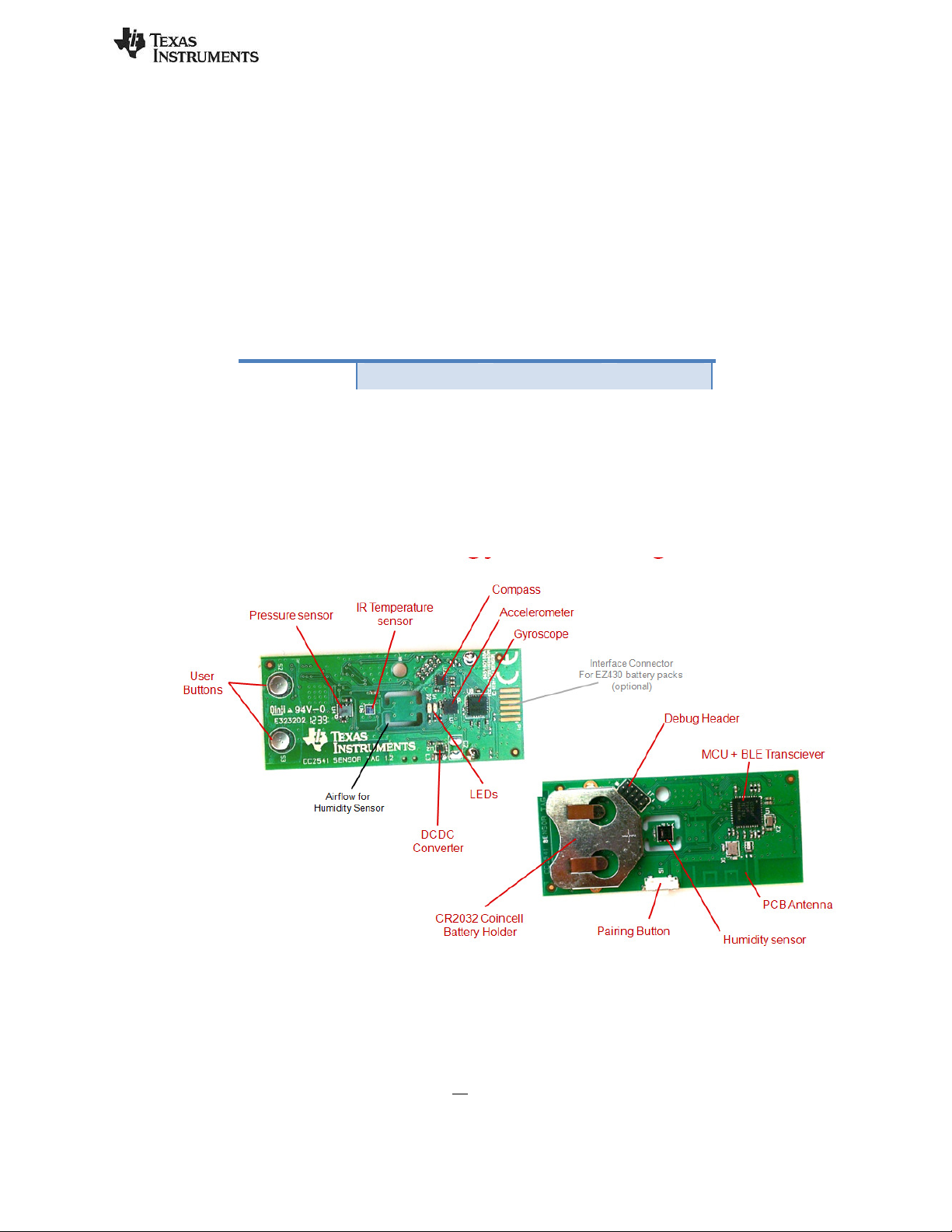
The CC2541 Sensor Tag is designed to act as a Peripheral Device (BLE Slave). Plastic casing for the sensor
tag is also included. The sensor tag operates on a single CR2032 coin cell battery and includes a twocolored LED and the following sensors: temperature, humidity, pressure, accelerometer, gyroscope, and
magnetometer.
The sensor tag uses I2C to interface to the different sensors. It is a FCC, IC, and ETSI certified solution. An
overview of the sensor tag is shown below:
The CC2540 USB Dongle can be used to emulate any type of Bluetooth low energy behavior but is usually
used as a Central Device (BLE Master). It connects to a Windows PC’s USB Port, and is pre-loaded with the
necessary software to receive commands from the PC tool BTool. That is, it acts as a network processor
by default.
Caution! The kits include a non-rechargeable lithium battery. Always make sure the battery is removed from the CC2540/41 Sensor
tag when it is connected to an external power source (Do not apply voltage > 3.6V). Dispose the battery properly and keep out of the
reach of children. If swallowed, contact a physician immediately.
Caution! The kits contain ESD sensitive components. Handle with care to prevent permanent damage.
Page 2 of 30
Page 3
SWRU270C
1.2 System Requirements
To use the TI BLE software, a PC running Microsoft Windows (XP or later) is required, as well as Microsoft
.NET Framework 3.5 Service Pack 1 (SP1) or greater.
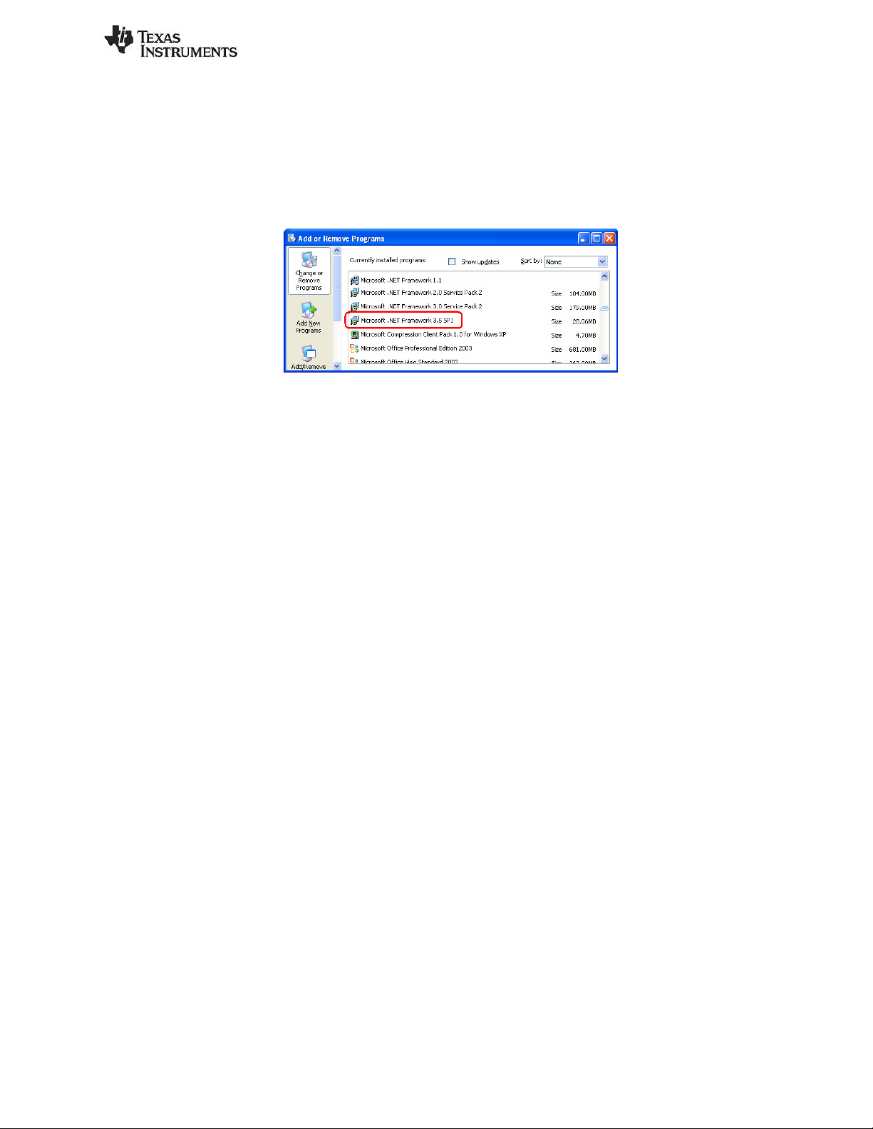
In order to check whether your system has the appropriate .NET Framework, open up the Windows
Control Panel, and select “Add or Remove Programs”. Amongst the list of currently installed programs,
you should see “Microsoft .NET Framework 3.5 SP1”, as shown in Figure 1:
Figure 1 System Requirements, .NET Framework 3.5 SP1
If you do not see it in the list, you can download the framework from Microsoft.
From a hardware standpoint, the Windows PC must contain one free USB port. An additional free USB
port is required in order to use the CC Debugger and the USB Dongle simultaneously.
IAR Embedded Workbench for 8051 development environment is required in order to make changes to
the sensor tag software. More information on IAR can be found in the Texas Instruments Bluetooth® Low
Energy Software Developer’s Guide Error! Reference source not found..
Page 3 of 30
Page 4
SWRU270C
2. Getting Started
This section describes how to set up the software and get started with the Development Kit. It is assumed
that the Sensor tag comes pre-programmed out of the box. If not, please see Chapter 4 for details on how
to program the sensor tag with the latest firmware. In addition, this section assumes that the latest
version of the TI BLE software (v1.3.1 as of the release of this document) has been installed. The latest BLE
software can be downloaded at www.ti.com/ble-stack.
2.1 Associate Driver with USB Dongle
After the software installation is complete, the USB Dongle driver must be associated with the device in
order to use the demo application. To associate the USB Dongle driver, first you must connect the USB
Dongle to the PC’s USB port, or to a USB hub that connects to the PC.
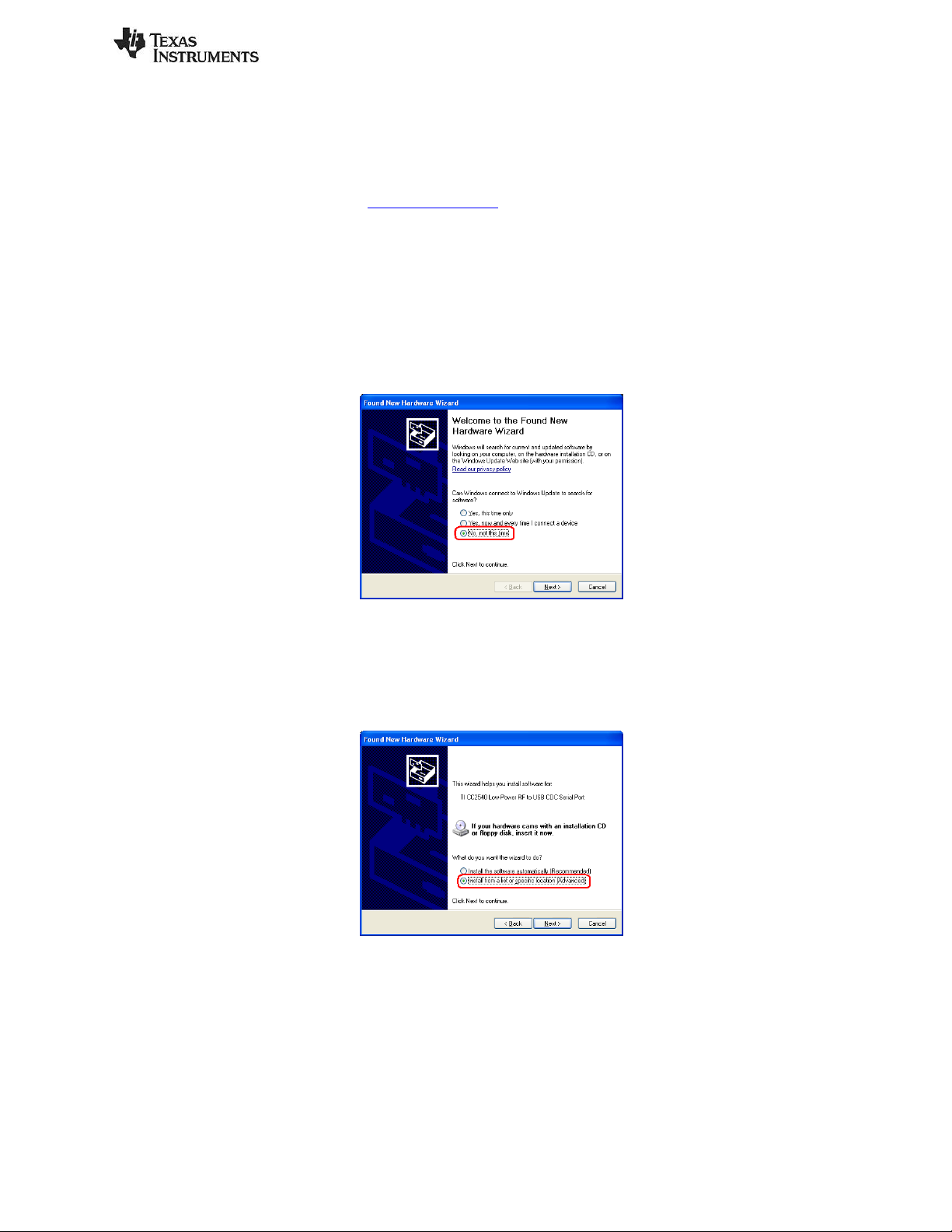
The first time that the dongle is connected to the PC, a message will most probably pop-up, indicating
that Windows does not recognize the device.
Figure 2 PC, Found New Hardware
When prompted whether to use Windows Update search for software, select “No, not this time” and
press the “Next” button. On the next screen, select the option “Install from a list or specific location
(Advanced)”, and press the “Next” button:
Figure 3 PC, Install Driver
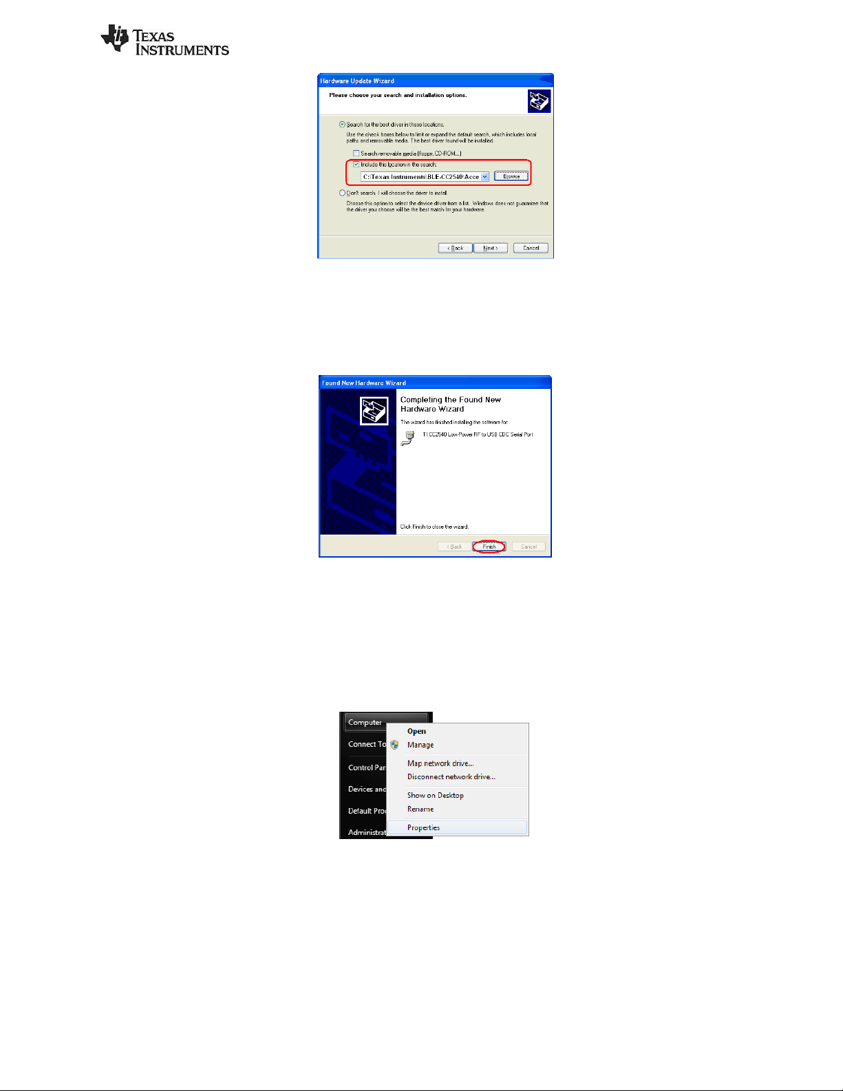
On the next screen, click the checkbox labeled “Include this location in the search:”, and click the
“Browse” button. Select the following directory (assuming the default installation path was used):
C:\Texas Instruments\BLE-CC254x-1.3.1\Accessories\Drivers
Page 4 of 30
Page 5
SWRU270C
Figure 4 PC, Select Driver
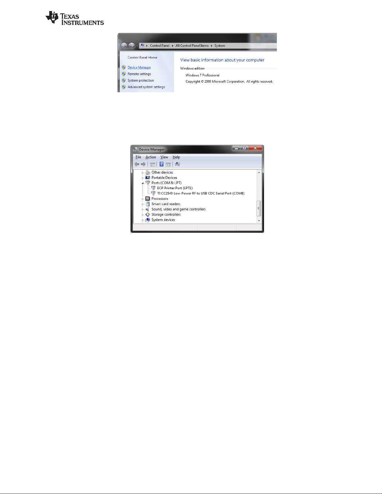
Click the “Next” button. This should install the driver. It will take a few seconds for the file to load. If the
installation was successful, you should see the screen to the below. Click the “Finish” button to complete
the installation.
Figure 5 PC, CDC Driver Installation Complete
2.2 Determining the COM Port
Once the driver is installed, you need to determine which COM port Windows has assigned to the USB
Dongle. After you have completed the USB Dongle driver association in section 2.1, right-click on the
“Computer” icon on your Start and select “Properties”, as shown in Figure 5.
Figure 6 Win7 PC, Finding Computer Properties
The “System Properties” window should open up. Click “Device Manager as shown in Figure 7.
Page 5 of 30
Page 6
SWRU270C
Figure 7 Win7 PC, Finding Device Manager
A list of all hardware devices should appear. Under the section “Ports (COM & LPT)”, the device “TI
CC2540 Low-Power RF to USB CDC Serial Port” should appear. Next to the name should be the port
number (for example, the CC2540USB Dongle uses COM8 in Figure 8).
Figure 8 Win7 PC, Connected Ports List
Take note of this port number, as it will be needed in order to use BTool. You may close the device
manager at this point.
Page 6 of 30
Page 7

SWRU270C
3. Using BTool
BTool is a PC Application that allows a user to form a connection between two BLE devices. BTool works
by communicating with the CC2540 USB Dongle, acting as a network processor, by means of HCI vendor
specific commands. The USB Dongle software (when running the HostTestRelease project) and driver
create a virtual serial port over the USB interface. BTool, running on the PC, communicates with the USB
Dongle through this virtual serial port.
More information on the network processor configuration and the HostTestRelease project can be found
in the Texas Instruments Bluetooth® Low Energy Software Developer’s Guide. More information on the
HCI interface, as well as details on the HCI vendor specific commands that are used by the CC2540/41, can
be found in the TI BLE Vendor Specific HCI Reference Guide. These documents can be found in the
Documents folder of the stack install directory.
For this section, a PC running windows 7 has been used, but the procedures are essentially the same for
other windows version, such as XP.
3.1 Starting the Application
To start the application, go into your programs by choosing Start > Programs > Texas Instruments > BLECC254x-1.3.1 > BTool. On Start-up you should be able to set the Serial Port Settings. Set the “Port” value
to the COM port earlier noted in Section 3.2. For the other settings, use the default values as shown in
Figure 9. Press “OK” to connect to the CC2540 USB Dongle.
Figure 9 BTool, Serial Port settings
When connected you should see the screen presented in Figure 10. The screen indicates that you now
have a serial port connection to the CC2540 USB Dongle. The screen is divided up into a few sections: the
left sidebar contains information on the CC2540 USB Dongle status. The left side of the sub-window
contains a log of all messages sent from the PC to the CC2540 USB Dongle and received by the PC from
the CC2540 USB Dongle. The right side of the sub-window contains a GUI for control of the CC2540 USB
Dongle. The bottom pane is the attribute explorer which we will discuss later on.
Page 7 of 30
Page 8

Device Information
SWRU270C
Message Log
Device Control
Figure 10 BTool, Overview
3.2 Creating a BLE Connection between USB Dongle and Sensor tag
At this point the USB Dongle (central) is ready to discover other BLE devices that are advertising. The
sensor tag should be preloaded with the sensor tag application. The full project and application source
code files for the sensor tag are included in the BLE software development kit.
At this time you will want to insert the battery (or remove and re-insert the battery to reset the device)
into the sensor tag (peripheral). You should also assemble the plastic and rubber portions of the kit to
minimize ESD on the board.
In order to ensure that you are connecting to the correct device, you need to know your sensor tag’s
address. To save time for this tutorial, we have included your address on the bottom of the lid of your
development kit. Alternatively, you can refer to section 5.3.2 for instructions to read the sensor tag’s
primary address.
3.2.1 Making the Sensor tag Discoverable
When the sensor tag powers up, it will not immediately go into a discoverable state. To enable advertising
and make the sensor tag discoverable, press the “pairing button” on the side of the sensor tag once. This
will turn advertisements on; making the device discoverable for 30 seconds (this value is defined in the
Specification of the Bluetooth System). After that time, the device will return to standby mode. To make
the device discoverable again, simply press the button once again. During discoverable mode, the LED will
flash green.
Page 8 of 30
Page 9

Figure 11 Press Side Button to Turn On Advertisements
3.2.2 Scanning for Devices
In BTool, Press the “Scan” button under the “Discover / Connect” tab, as shown in Figure 12.
SWRU270C
Figure 12 BTool, Scan for Devices
The USB Dongle will begin search for other BLE devices. As devices are found, the log on the left side of
the screen will display the devices discovered. After 10 seconds, the device discovery process will
complete, and the USB Dongle will stop scanning. A summary of all the scanned devices will be displayed
in the log window. In the example in Figure 13, one peripheral device was discovered while scanning. If
you do not want to wait through the full 10 seconds of scanning, the “Cancel” button can be pressed
alternatively, which will stop the device discovery process. The address of any scanned devices will appear
in the “Slave BDA” section of the “Link Control” section in the bottom right corner of the sub-window.
Page 9 of 30
Page 10
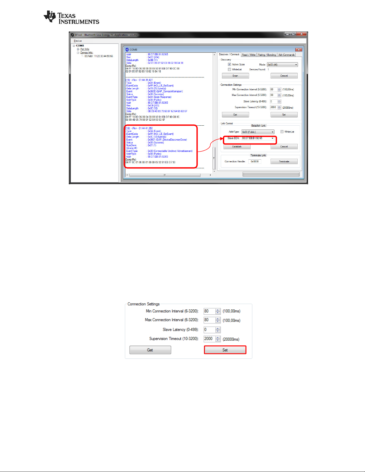
Figure 13 BTool, Slave Address
SWRU270C
3.2.3 Selecting Connection Parameters
Before establishing a connection, you can set up the desired connection parameters. The default values of
100ms connection interval, 0 slave latency, and 20s supervision timeout should serve as a good starting
point; however for different applications you may want to experiment with these values.
Once the desired values have been set, be sure to click the “Set” button; otherwise the settings will not be
saved. Note that the connection parameters must be set before a connection is established; changing the
values and clicking the “Set” button while a connection is active will not change the settings of an active
connection. The connection must be terminated and re-established to use the new parameters. (The
Bluetooth specification does support connection parameter updates while a connection is active; however
this must be done using either an L2CAP connection parameter update request, or using a direct HCI
command. More information can be found in the Specification of the Bluetooth System)
Figure 14 BTool, Connection Settings
3.2.4 Establishing a Connection
To establish a connection with the sensor tag, select the address of the device to connect with and click
the “Establish” button as shown in Figure 15.
Page 10 of 30
Page 11

SWRU270C
Figure 15 BTool, Establish Connection
If the sensor tag is still in discoverable mode, a connection should be established (if more than 30 seconds
have passed since the device was previously made discoverable, press the right button on the sensor tag
once again). Once a connection is established, the message window will return a “GAP_EstablishLink”
event message with a “Status” value of “0x00 (Success)” as shown in Figure 16.
Figure 16 BTool Log, Link Established
In BTool, you can see your connected peripheral device in the Device Information field, as shown in Figure
17.
Figure 17 BTool, Device Information
3.3 Using the Sensor Tag’s GATT Profiles
We will now begin investigating the sensor tag’s GATT profiles. Besides the standard GAP, GATT, and
device information services, the sensor tag contains the following GATT services: temperature,
accelerometer, humidity, magnetometer, barometer, gyroscope, simple keys, and test. You will find the
sensor tag complete attribute below and it can be used as a reference. Services are shown in yellow,
characteristics are shown in blue, and characteristic values / descriptors are shown in grey.
Services are constructed of characteristics, each of which have, at minimum, a declaration and a value,
and may have a client configuration and/or a user description. The actual payload data is stored with the
characteristic values. All application data that is being sent or received in Bluetooth low energy must be
contained within characteristic values. This section details a step-by-step process that demonstrates
several processes for reading, writing, discovering, and notifying GATT characteristic values using BTool.
In a Bluetooth low energy system, upon connection, the Central Device (GATT Client) performs a service
discovery on the Peripheral device (GATT server) to build up an attribute table. This attribute table will
provide handles (internal addresses of the characteristics) which can be used by the Client to access the
data located in the Server. The service discovery is typically an automated process that can be started
with a single command. In BTool however, the automated service discovery is not implemented (although
it’s still possible to perform it manually). To simplify the evaluation of the sensor tag, the attribute table
will be known and is shown below so it is possible to use handles directly to read out data.
Page 11 of 30
Page 12

handle
02 (read permis sions)
SWRU270C
Sensor Tag Application: Complete Attribute Table
TI Base UUID: F000XXXX-0451-4000-B000-000000000000. 128-but UUIDs are typed 'b old'
02 (properties: read only)
03 00 (handle: 0x0003)
00 2A (UUID: 0x2A 00)
02 (properties: read only)
05 00 (handle: 0x0005)
01 2A (UUID: 0x2A 01)
0A (properties: read/w rite)
07 00 (handle: 0x0007)
02 2A (UUID: 0x2A 02)
0A (properties: read/w rite)
09 00 (handle: 0x0009)
03 2A (UUID: 0x2A 03)
02 (properties: read only)
0B 00 (handle: 0x000B)
04 2A (UUID: 0x2A 04)
50 00 (100ms preferr ed min connection interval)
A0 00 (200ms preferred max connection interval)
00 00 (0 preferred slave latency)
E8 03 (10000ms preferred s upervision timeout)
20 (properties: indicate only)
0E 00 (handle: 0x000E)
05 2A (UUID: 0x2A 05)
0x180A (DEVINFO_SERV_UUID) GATT_PERMIT_READ Start of Device Information Service
02 (read permis sions)
11 00 (handle 0x0011)
23 2A (UUID 0x2A 23) GATT_PERMIT_READ
xx x x xx 00 00 xx xx x x (xx 's are IEEE address ) GATT_PERMIT_READ System ID
02 (read permis sions)
13 00 (handle 0x0013)
24 2A (UUID 0x2A 24) GATT_PERMIT_READ
"Model Number" GATT_PERMIT_READ Model Number String
02 (read permis sions)
15 00 (handle 0x0015)
25 2A (UUID 0x2A 25) GATT_PERMIT_READ
"Serial Number" GATT_PERMIT_REA D Serial Number String
02 (read permis sions)
17 00 (handle 0x0017)
26 2A (UUID 0x2A 26) GATT_PERMIT_READ
"Firmw are Revision" GATT_PERMIT_READ Firmwar e Revision String
02 (read permis sions)
19 00 (handle 0x0019)
27 2A (UUID 0x2A 27) GATT_PERMIT_READ
"Hardware Revision" GATT_PERMIT_READ Hardw are Rev ision String
02 (read permis sions)
1B 00 (handle 0x001B)
28 2A (UUID 0x2A 28) GATT_PERMIT_READ
"Softw are Revision" GATT_PERMIT_READ Softw are Rev ision String
02 (read permis sions)
1D 00 (handle 0x001D)
29 2A (UUID 0x2A 29) GATT_PERMIT_READ
"Manufactur er Name" GATT_PERMIT_READ Manufacturer Name Str ing
02 (read permis sions)
1F 00 (handle 0x001F)
2A 2A (UUID 0x2A2A ) GATT_PERMIT_READ
FE 00 65 78 70 65 72 69 6D 65 6E 74 61 6C GATT_PERMIT_READ IEEE 11073-20601 Regulatory Certification Data List
22 00 (handle 0x0022)
50 2A (UUID 0x2A 50) GATT_PERMIT_READ PnP ID characteristic declaration
FE 00 65 78 70 65 72 69 6D 65 6E 74 61 6C GATT_PERMIT_READ PnP ID
GATT Server
Per mis sio ns
GATT_PERMIT_READ Device Name characteristic declaration
GATT_PERMIT_READ Appearance charac teristic declaration
GATT_PERMIT_READ Peripheral Privacy Flag characteristic declaration
GATT_PERMIT_READ |
GATT_PERMIT_WRITE
GATT_PERMIT_READ Reconnection address characteristic declaration
GATT_PERMIT_READ |
GATT_PERMIT_WRITE
GATT_PERMIT_READ
GATT_PERMIT_READ
GATT_PERMIT_READ Service Changed characteristic declaration
GATT_PERMIT_READ |
GATT_PERMIT_WRITE
Notes
Peripheral Privacy Flag characteristic v alue
Reconnection address characteristic value
Peripheral Pref erred Connection Parameters
characteristic dec laration
Peripheral Pref erred Connection Parameters
characteristic dec laration
Write "01:00" to enable notifications, "00:00" to disable
System ID
characteristic dec laration
Model Number String
characteristic dec laration
Serial Number String
characteristic dec laration
Firmw are Revision String
characteristic dec laration
Hardware Revision String
characteristic dec laration
Softw are Revision String
characteristic dec laration
Manufacturer Name Str ing
characteristic dec laration
IEEE 11073-20601 Regulatory Certification Data List
characteristic dec laration
(de c)
Type
(he x)
Type (#DEFINE) Hex / Text V alue (d efault )
handle
(he x)
0x1 1 0x2800 GATT_PRIMARY_SERVICE_UUID 0x1800 (GAP_SERVICE_UUID) GATT_PERMIT_READ Start of GAP Service (Mandatory)
0x2 2 0x2803 GATT_CHA RACTER_UUID
0x3 3 0x2A00 GAP_DEVICE_NAME_UUID "Sensor Tag" GATT_PERMIT_READ Device Name characteristic value
0x4 4 0x2803 GATT_CHA RACTER_UUID
0x5 5 0x2A01 GAP_APPEARANCE_UUID 0x0000 GATT_PERMIT_READ Appearance charac teristic value
0x6 6 0x2803 GATT_CHA RACTER_UUID
0x7 7 0x2A02 GAP_PERI_PRIVA CY_FLA G_UUID 0x00 (GAP_PRIVACY_DISA BLED)
0x8 8 0x2803 GATT_CHA RACTER_UUID
0x9 9 0x2A03 GAP_RECONNECT_ADDR_UUID 00:00:00:00:00:00
0xA 10 0x2803 GATT_CHARACTER_UUID
0xB 11 0x2A04 GAP_PERI_CONN_PARAM_UUID
0xC 12 0x2800 GATT_PRIMA RY_SERVICE_UUID 0x1801 (GATT_SERVICE_UUID) GATT_PERMIT_READ Start of GATT Service (mandatory)
0xD 13 0x2803 GATT_CHARACTER_UUID
0xE 14 0x2A05 GATT_SERVICE_CHA NGED_UUID (null value) (none) Service Changed characteristic value
0xF 15 0x2902 GA TT_CLIENT_CHAR_CFG_UUID 00:00 (2 bytes)
0x10 16 0x2800 GATT_PRIMA RY_SERVICE_UUID
0x11 17 0x2803 GATT_CHARACTER_UUID
0x12 18 0x2A23 DEVINFO_SY STEM_ID_UUID
0x13 19 0x2803 GATT_CHARACTER_UUID
0x14 20 0x2A24 DEV INFO_MODEL_NUMBER_UUID
0x15 21 0x2803 GATT_CHARACTER_UUID
0x16 22 0x2A25 DEV INFO_SERIAL_NUMBER_UUID
0x17 23 0x2803 GATT_CHARACTER_UUID
0x18 24 0x2A26 DEVINFO_FIRMWA RE_REV _UUID
0x19 25 0x2803 GATT_CHARACTER_UUID
0x1A 26 0x2A27 DEVINFO_HARDWARE_REV_UUID
0x1B 27 0x2803 GATT_CHARACTER_UUID
0x1C 28 0x 2A28 DEVINFO_SOFTWA RE_REV_UUID
0x1D 29 0x2803 GATT_CHARACTER_UUID
0x1E 30 0x2A 29 DEVINFO_MA NUFACTURER_NAME_UUID
0x1F 31 0x2803 GATT_CHA RACTER_UUID
0x20 32 0x 2A2A DEV INFO_11073_CERT_DATA_UUID
0x21 33 0x2803 GATT_CHARACTER_UUID
0x22 34 0x 2A2A PNPID_DATA_UUID
Page 12 of 30
Page 13

0x23
0x24
0x25
0x26
0x27 39 0x2901 GATT_CHA R_USER_DESC_UUID "IR Temp. Data" (14 bytes) GATT_PERMIT_REA D
0x28
0x29
0x2A 42 0x2901 GATT_CHAR_USER_DESC_UUID "IR Temp. Conf." (15 bytes) GATT_PERMIT_REA D
0x2B
0x2C
0x2D 45
0x2E
0x2F 47 0x2901 GATT_CHAR_USER_DESC_UUID "A ccel. Data" (14 bytes) GATT_PERMIT_REA D
0x30
0x31
0x32 50 0x2901 GATT_CHA R_USER_DESC_UUID "A ccel. Conf." (15 bytes) GATT_PERMIT_REA D
0x33
0x34
0x35 53 0x2901 GATT_CHA R_USER_DESC_UUID "A cc. Period" (12 bytes) GATT_PERMIT_READ
0x36
0x37
0x38 56
0x39
0x3A 58 0x2901 GATT_CHAR_USER_DESC_UUID "Humid. Data" (14 by tes) GATT_PERMIT_READ
0x3B
0x3C
0x3D 61 0x2901 GATT_CHAR_USER_DESC_UUID "Humid. Conf ." (15 bytes) GATT_PERMIT_READ
0x3E
0x3F
0x40 64
0x41
0x42 66 0x2901 GATT_CHA R_USER_DESC_UUID "Mag. Data" ( 10 bytes) GATT_PERMIT_READ
0x43
0x44
0x45 69 0x2901 GATT_CHA R_USER_DESC_UUID "Mag. Conf ." (11 bytes) GATT_PERMIT_READ
0x46
0x47
0x48 72 0x2901 GATT_CHA R_USER_DESC_UUID "Mag. Period" (12 bytes) GATT_PERMIT_REA D
0x2800 GATT_PRIMA RY _SERVICE_UUID
35
0x2803 GATT_CHARACTER_UUID
36
0xAA01
37
0x2902 GATT_CLIENT_CHAR_CFG_UUID 00:00 (2 bytes)
38
IRTEMPERATURE_DA TA_UUID 00:00:00:00 (4 bytes) GATT_PERMIT_READ ObjectLSB:ObjectMSB:AmbientLSB:AmbientMSB
0x2803 GATT_CHARACTER_UUID
40
0xAA02
41
IRTEMPERATURE_CONF_UUID 1 ( 1 byte)
0x2800 GATT_PRIMA RY _SERVICE_UUID
43
0x2803 GATT_CHARACTER_UUID
44
0xAA11
0x2902 GATT_CLIENT_CHAR_CFG_UUID 00:00 (2 bytes)
46
0x2803 GATT_CHARACTER_UUID
48
0xAA12
49
ACCELEROMETER_DA TA_UUID 00:00:00 (3 bytes) GATT_PERMIT_REA D X : Y : Z Coordinates
ACCELEROMETER_CONF_UUID 1 (1 byte)
0x2803 GATT_CHARACTER_UUID
51
0xAA13
52
0x2800 GATT_PRIMA RY _SERVICE_UUID
54
0x2803 GATT_CHARACTER_UUID
55
0xAA21
0x2902 GATT_CLIENT_CHAR_CFG_UUID 00:00 (2 bytes)
57
ACCELEROMETER_PERI_UUID 1 (1 byte)
HUMIDITY_DATA_UUID 00:00:00:00 (4 bytes) GATT_PERMIT_READ TempLSB:TempMSB:HumidityLSB:HumidityMSB
0x2803 GATT_CHARACTER_UUID
59
0xAA22
60
0x2800 GATT_PRIMA RY _SERVICE_UUID
62
0x2803 GATT_CHARACTER_UUID
63
0xAA31
0x2902 GATT_CLIENT_CHAR_CFG_UUID 00:00 (2 bytes)
65
HUMIDITY_CONF_UUID 1 (1 byte)
MAGNETOMETER_DATA_UUID 00:00:00:00:00:00 (6 bytes) GATT_PERMIT_READ XLSB:XMSB:YLSB:YMSB: ZLSB:ZMSB Coordinates
0x2803 GATT_CHARACTER_UUID
67
0xAA32
68
0x2803 GATT_CHARACTER_UUID
70
0xAA33
71
MAGNETOMETER_CONF_UUID 1 (1 byte)
MAGNETOMETER_PERI_UUID 1 (1 byte)
(IRTEMPERATURE_SERV_UUID ) GATT_PERMIT_REA D Start of Sensor Pr ofile Temperature Service
0xAA00
12 (properties: read/notify)
25 00 (handle: 0x0025)
01 AA (UUID:
0A (properties: read/w rite)
29 00 (handle: 0x0029)
02AA ( UUID:
(ACCELEROMETER_SERV_UUID ) GATT_PERMIT_REA D Start of Sensor Pr ofile Acc elerometer Service
0xAA10
12 (properties: read/notify)
2D 00 (handle: 0x002D)
11 AA (UUID:
0A (properties: read/w rite)
31 00 (handle: 0x0031)
12 AA (UUID:
0A (properties: read/w rite)
34 00 (handle: 0x0034)
13 AA (UUID:
(HUMIDITY_SERV_UUID ) GATT_PERMIT_READ Start of Sensor Profile Humidity Service
0xAA20
12 (properties: read/notify)
38 00 (handle: 0x0038)
21 AA (UUID:
0A (properties: read/w rite)
3C 00 (handle: 0x003C)
22 AA (UUID:
(MAGNETOMETER_SERV_UUID ) GATT_PERMIT_REA D Start of Sensor Pr ofile Magnetometer Serv ice
0xAA30
12 (properties: read/notify)
40 00 (handle: 0x0040)
31 AA (UUID:
0A (properties: read/w rite)
44 00 (handle: 0x0044)
32 AA (UUID: 0xAA 32)
0A (properties: read/w rite)
47 00 (handle: 0x0047)
33 AA (UUID:
0xAA01
0xAA02
0xAA11
0xAA12
0xAA13
0xAA21
0xAA22
0xAA31
0xAA33
)
)
)
)
)
)
)
)
)
GATT_PERMIT_REA D
GATT_PERMIT_READ |
GATT_PERMIT_WRITE
GATT_PERMIT_REA D
GATT_PERMIT_READ |
GATT_PERMIT_WRITE
GATT_PERMIT_REA D
GATT_PERMIT_READ |
GATT_PERMIT_WRITE
GATT_PERMIT_REA D
GATT_PERMIT_READ |
GATT_PERMIT_WRITE
GATT_PERMIT_REA D
GATT_PERMIT_READ |
GATT_PERMIT_WRITE
GATT_PERMIT_REA D
GATT_PERMIT_READ |
GATT_PERMIT_WRITE
GATT_PERMIT_REA D
GATT_PERMIT_READ |
GATT_PERMIT_WRITE
GATT_PERMIT_REA D
GATT_PERMIT_READ |
GATT_PERMIT_WRITE
GATT_PERMIT_REA D
GATT_PERMIT_READ |
GATT_PERMIT_WRITE
GATT_PERMIT_REA D
GATT_PERMIT_READ |
GATT_PERMIT_WRITE
SWRU270C
Write "01:00" to enable notifications, "00:00" to disable
Write "01" to start Sensor and Measurements, "00" to
put to sleep
Write "01:00" to enable notifications, "00:00" to disable
Write "01" to start Sensor and Measurements, "00" to
put to sleep
Period = [Input*10] ms, default 1000 ms , low er limit 100
ms
Write "01:00" to enable notifications
Write "01" to start Sensor and Measurements, "00" to
put to sleep
Write "01:00" to enable notifications, "00:00" to disable
Write "01" to start Sensor and Measurements, "00" to
put to sleep
Period = [Input*10]ms, default 2000ms , low er limit 100
ms
Page 13 of 30
Page 14

to enable Y axis only, 3 = X and Y, 4 = Z only, 5 = X and
GATT_PERMIT_READ |
0x49
0x4A
0x4B 75 0xAA41 BAROMETER_DA TA_UUID 00:00:00:00 (4 bytes) GATT_PERMIT_READ TempLSB:TempMSB:PressureLSB:Pressure MSB
0x4C
0x4D 7 7 0x2901 GATT_CHAR_USER_DESC_UUID "Barometer Data" (15 bytes ) GATT_PERMIT_REA D
0x4E
0x4F
0x50 80 0x2901 GATT_CHAR_USER_DESC_UUID "Barometer Conf ." (16 bytes) GATT_PERMIT_REA D
0x51
0x52
0x53
0x54 84 0x2901 GATT_CHAR_USER_DESC_UUID "Barometer Cali." (16 bytes) GATT_PERMIT_REA D
0x55 85 0x2800 GATT_PRIMA RY_SERVICE_UUID 0xAA50 (GYROSCOPE_SERV_UUID ) GATT_PERMIT_REA D Start of Sensor Profile Gy roscope Service
0x56 86 0x2803 GATT_CHARACTER_UUID
0x57 87 0xAA51 GYROSCOPE_DATA_UUID 00:00:00:00:00:00 (6 bytes) GA TT_PERMIT_READ XLSB:XMSB:YLSB:YMSB: ZLSB:ZMSB
0x58 88 0x2902 GA TT_CLIENT_CHAR_CFG_UUID 00:00 (2 bytes)
0x59 89 0x2901 GATT_CHAR_USER_DESC_UUID "Gyro. Data" (11 bytes) GATT_PERMIT_READ
0x5A 90 0x2803 GATT_CHARACTER_UUID
0x5B 91 0xAA52 GYROSCOPE_CONF_UUID 1 (1 byte)
0x5C 9 2 0x2901 GATT_CHAR_USER_DESC_UUID "Gyro. Conf." (13 bytes) GATT_PERMIT_READ
0x5D
0x5E
0x5F
0x60
0x61 97 0x2901 GATT_CHAR_USER_DESC_UUID "Key Press State" GATT_PERMIT_READ Key s state characteris tic user description
0x62 98 0x2800 GATT_SERVICE_UUID 0xAA60 (TEST_SERVICE_UUID) GATT_PERMIT_READ Start of TestService
0x63
0x64 100 0xAA61 TEST_DATA_UUID 1 byte GATT_PERMIT_READ Test Data: 1 bit set of each test passed
0x65 101 0x2901 GATT_CHAR_USER_DESC_UUID "Test Data" (10 bytes) GATT_PERMIT_READ
0x66
0x67
0x68 104 0x2901 GATT_CHAR_USER_DESC_UUID "Test Config" (12 bytes) GATT_PERMIT_REA D
0x2800 GATT_PRIMA RY_SERVICE_UUID 0xAA40 (BAROMETER_SERV_UUID ) GATT_PERMIT_REA D Start of Sensor Profile Barometer Service
73
0x2803 GA TT_CHARACTER_UUID
74
0x2902 GATT_CLIENT_CHAR_CFG_UUID 00:00 (2 bytes)
76
0x2803 GA TT_CHARACTER_UUID
78
0xAA42 BA ROMETER_CONF_UUID 1 (1 byte)
79
0x2803 GA TT_CHARACTER_UUID
81
0xAA43 BAROMETER_CA LI_UUID 00:00:...:00:00 (16 bytes) GATT_PERMIT_READ
82
0x2902 GATT_CLIENT_CHAR_CFG_UUID 00:00 (2 bytes)
83
12 (properties: read/notify)
4B 00 (handle: 0x004B)
41 AA (UUID: 0xAA41)
0A (properties: read/w rite)
53 00 (handle: 0x0053)
42 AA (UUID: 0xAA42)
02 (properties: read only)
4F 00 (handle: 0x004F)
43 AA (UUID: 0xAA43)
GATT_PERMIT_REA D
GATT_PERMIT_REA D |
GATT_PERMIT_WRITE
GATT_PERMIT_REA D
GATT_PERMIT_REA D |
GATT_PERMIT_WRITE
GATT_PERMIT_REA D
GATT_PERMIT_REA D |
GATT_PERMIT_WRITE
Write "01" to start Sensor and Measur ements, "00" to
put to sleep, "02" to read calibration values fr om sensor
When wr ite 02 to Barometer Conf. has been issued, the
calibration values is found here
93
0x2800 GATT_SERVICE_UUID 0xFFE0 (SK_KEYPRESSED_UUID) GATT_PERMIT_READ Start of Simple Keys Service
94
0x2803 GATT_CHARACTER_UUID
95
0xFFE1 SK_KEY PRESSED_UUID 0 (none)
96
0x2902 GATT_CLIENT_CHAR_CFG_UUID 0x0000
99
0x2803 GATT_CHARACTER_UUID
12 (properties: read/notify)
57 00 (handle: 0x0057)
51 AA (UUID: 0xAA51)
0A (properties: read/w rite)
5B 00 (handle: 0x005B)
52 AA (UUID: 0xAA52)
10 (notify permission)
34 00 (handle 0x0034)
E1 FF (UUID 0xFFE1) GATT_PERMIT_REA D Keys state c haracteristic declaration
02 (read permis sion)
64 00 (handle 0x0064)
61 AA (UUID: 0xAA61) GATT_PERMIT_READ Test Data characteristic declaration
GATT_PERMIT_REA D
GATT_PERMIT_REA D |
GATT_PERMIT_WRITE
GATT_PERMIT_REA D
GATT_PERMIT_REA D |
GATT_PERMIT_WRITE
GATT_PERMIT_WRITE
Write 0 to turn off gyros cope, 1 to enable X axis only, 2
Z, 6 = Y and Z, 7 = X, Y and Z
Keys state charac teristic value (bit mas k of left / right
key presses ). Side key as bit 2 in test mode only.
102
0x2803 GATT_CHARACTER_UUID
103
0xAA62 TEST_CONFIG_UUID 1 byte GA TT_PERMIT_READ
0A (read/w rite permiss ion)
68 00 (handle 0x0068)
62 AA (UUID: 0xAA62) GATT_PERMIT_READ Test Config characteristic dec laration
Test Config: bit 7 - enable test mode, bit 1 - set LED2, bit
0 - set LED 1
SWRU270C
Page 14 of 30
Page 15
SWRU270C
3.3.1 Reading a Characteristic Value by UUID
A characteristic value is essentially where the data payload is stored, which could be, for example,
temperature data or battery level. It is the stored data in a server that a client wants to access. A
characteristic is a discrete value that has, at minimum, the following three properties associated with it:
1. A handle (address)
2. A type (UUID)
3. A set of permissions
Let’s consider the IR Temperature service: handles 0x23 to 0x2A as seen above. This service has two
characteristics: IR temperature data and IR temperature config. We must first enable the IR sensor by
writing to the IR temperature config characteristic. We can then read the temperature by reading from
the IR temperature data characteristic. First, let’s read the IR temperature config characteristic to ensure
that isn’t already enabled (it won’t be). The simplest way to read its value is to use the “Read
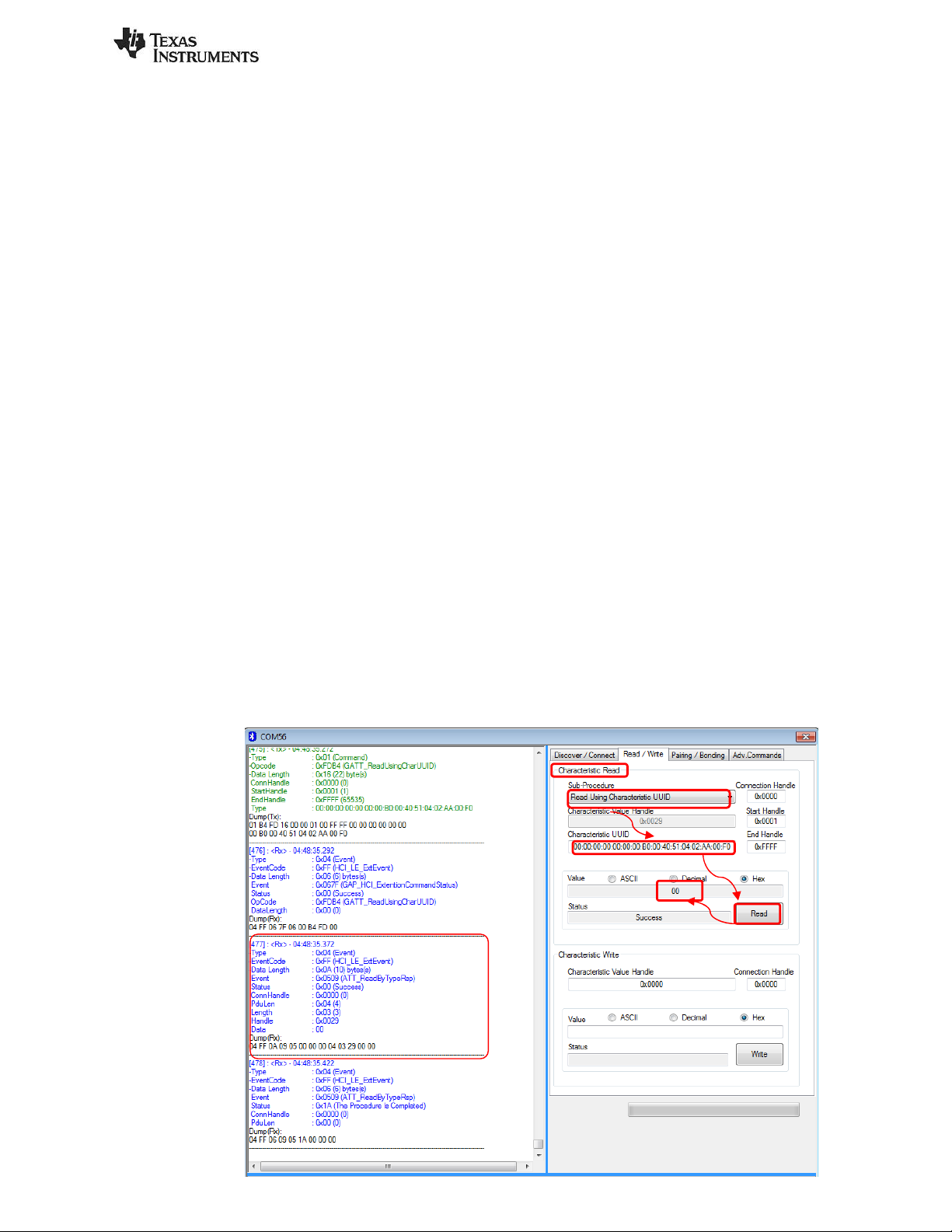
Characteristic by UUID” sub-procedure. To do this, you will first need to click the “Read / Write” tab in
BTool. Select the option “Read Using Characteristic UUID” under the “Sub-Procedure” option in the
“Characteristic Read” section at the top of the screen. Enter the UUID we are looking for. The UUID from
the table above is 0xAA02. However, this is a 128-bit UUID so we must add the TI Base UUID. The
effective UUID we are looking for is F000AA02-0451-4000-B000-000000000000. Also, we must enter this
LSB to MSB in BTool with each byte separated by a colon. So enter
00:00:00:00:00:00:00:B0:00:40:51:04:02:AA:00:F0 in the “Characteristic UUID” box, and click the “Read”
button as shown below.
An attribute protocol Read by Type Request packet gets sent over the air from the central device to the
peripheral device, and an attribute protocol Read by Type Response packet gets sent back from the
peripheral device to the central device. The value “00” is displayed in the “Value” box, and “Success” is
displayed in the “Status” box. The “00” indicates that the temperature sensor is not enabled. In addition,
the message window will display information on the Read by Type Response packet that was received by
the central device. The message includes not only the characteristic’s data value, but also the handle of
the characteristic value (0x0029 in this case).
****Note that, as you read attributes from the peripheral, the attribute table in the bottom pane begins
to fill up. You can actually fill this entire table up initially by choosing ATT_FindInfoReq in the Adv.
Commands tab. You can then read and write to many characteristics by clicking on their respective
column in the table. However, it is recommended to go through these manual steps first to gain
understanding.
Page 15 of 30
 Loading...