

Page 1
CC2530ZDK Quick Start Guide
SWRA274A
June 2010
1. Introduction
This guide describes how to set up a
ZigBee® sensor network demo
(consisting of sensor nodes and collector
nodes) using the preprogrammed devices
of the CC2530ZDK.
The sensors periodically report their
temperature and the collector nodes
ensure that the data gets routed to the
collector node that functions as gateway.
The collector node configured as gateway
is connected to the PC running the PC
application that visualizes the network
topology and the sensor data. More
information about the demo and the
source code can be found on the
CC2530ZDK product page [1].
The ZDK contains 2 CC2530EM’s
programmed as collector devices (both
can be used as gateway), and 5
CC2530EM’s programmed as sensor
devices.
The following steps describe how to
install & run the demo. Additionally, it is
shown how to get started with setting up
the development environment.
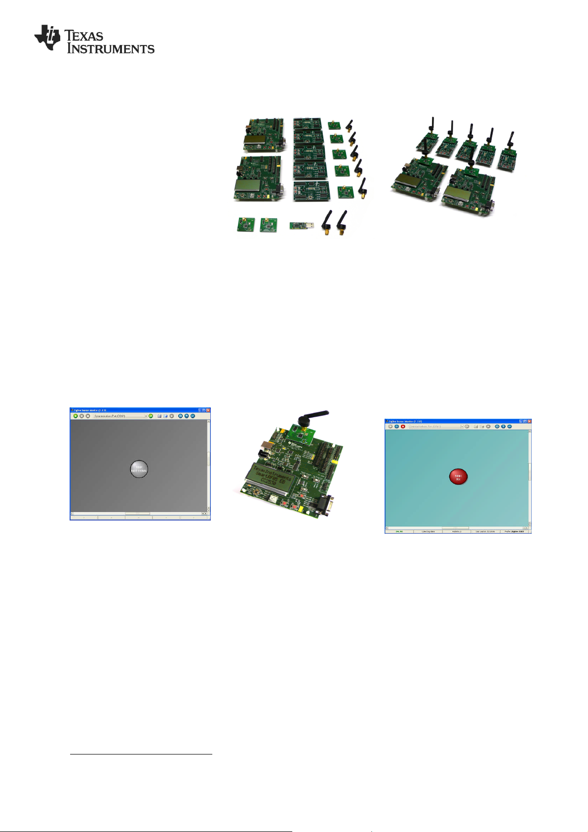
2. Kit Contents
2 x SmartRF05EB (the large boards)
5 x SmartRF05BB (the battery boards)
2 x CC2530EM (labeled COLLECTOR)
5 x CC2530EM (labeled SENSOR)
1 x CC2531 USB Dongle
7 x 2.4 GHz Antennas
Cables
Batteries
Documentation
The USB dongle is not directly used in
this demo. It can be us ed for over the air
packet sniffing (see also Step 12)
3. Assemble the boards
Assemble the boards that are included in
the CC2530ZDK:
Connect an antenna to each of the
CC2530EM’s
Mount the 2 Collector EM’s on top of
SmartRR05EB’s.
Mount the 5 Sensor EM’s on the
SmartRF05 Battery Boards.
Place the batteries in the sockets
underneath the boards. Wait with
powering up the boards until instructed.
On the EB boards set jumper P11 in
position for battery power. Place the EM
Selection switch on each of the EB’s and
BB’s in position SoC/TRX.
4. Install ZSensorMonitor
The ZSensorMonitor software can be
downloaded from the CC2530ZDK
product page [1].
Install it on your PC and launch the
application (zsensormonitor.exe). A
shortcut can be found under the Texas
Instruments folder on the Program menu.
Connect a serial cable from one of the
SmartRF05EB boards to the PC. This will
be the gateway node.
If you experience any problem (e.g. with
launching the ZSensorMonitor), please
consult the ZigBee Sensor Monitor User’s
Guide (ZSensorMonitor User's
Guide.pdf). It can be found under the
Texas Instruments folder on the Program
menu .
5. Power up gateway device
Make sure that P14 (the RS232 switch) is
set in position Enable on this board.
Power up the gateway device (the
SmartRF05EB connected to the PC with
serial cable). Press and hold joystick
center during power up.
After power up LED 1 and 2 are blinking
to indicate that the gateway device is
trying to connect to a network. Press
joystick up on the device. This will start
up a new PAN and this node will be the
ZigBee Coordinator. LED 1 will be
switched on.
Press Joystick right on the device. This
will make the device accept binding
requests and configure this node as the
gateway node. LED 2 will be switched on.
1
6. Connect with
ZSensorMonitor
Choose correct COM port from the drop
down list in the top and then press the
play button in the ZSensorMonitor User
Interface (in the upper left corner).
The node symbol will turn red to indicate
that the gateway node is detected by the
ZSensorMonitor application.
1
Press the joystick like a button and keep it pressed while powering up the board. Do not release the joystick
until a few seconds after power up. This will ensure a fresh startup, i.e. bypass the network and binding
information stored in Non Volatile memory.
1/2
Page 2
SWRA274A
June 2010
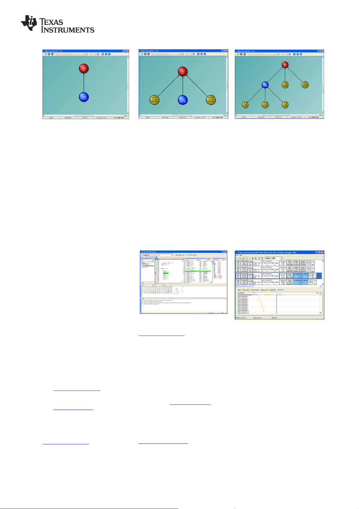
7. Power on collector device
Power up the other SmartRF05EB
(Collector device). Press joystick center
during power up1. The green LED 1 will
blink shortly during connecting to the
network. The red LED 2 will blink to
indicate it is in process of discovery and
binding. LED 1 and LED 2 will both be
switched on when the device has joined
the network and bound to the gateway.
Press joystick down to start sending
periodic reports from this device. The
collector node will be displayed as a blue
circle in the ZSensorMonitor as shown in
the image.
10. Demo of ZigBee Features
8. Add 2 sensor nodes
Add 2 of the sensor nodes (SmartRF05
Battery boards) to achieve the topology
shown above. Power them up one by one
and press joystick center during power
up1.
After the LED’s start blinking rapidly press
joystick down to start the reporting. The
two sensor nodes will appear in the
ZSensorMonitor as soon as their first
report is received.
Press joystick left on the gateway node
(device connected to the PC). The
gateway will then not accept new joining
requests in order to achieve the desired
topology (see step 9).
11. IAR Embedded Workbench
9. Add remaining sensors
Add the 3 remaining s ensors. Press
joystick center during power up1. These
sensors will not join the gateway but the
other Collector device since the gateway
is not accepting join requests.
After the LED’s start blinking rapidly press
joystick down to start reporting from
each of the sensors. All of the nodes will
appear in the ZSensorMonitor that will
display the reported temperature.
Congratulations! You have successfully
setup a small ZigBee network and the
sensor demo application.
12. Packet Sniffer
The resulting setup can be used to
demonstrate two of the many benefits
of the ZigBee protocol.
Range extension
The topology in the figure of Step 9
illustrates that ZigBee can be used to
extend the range of a network by using
hops between communicating nodes.
Self-healing
To demonstrate the self-healing feature of
ZigBee you can simply turn off the
collector device that is not connected to
the PC; then the sensors will join the
gateway device (if in radio range) as the
gateway does not allow new devices to
join, but it does allow re-joins of nodes
that are already in the network.
A. References and more
information
[1] CC2530 ZigBee Development Kit
www.ti.com/cc2530zdk
[2] CC2530 product web page
www.ti.com/cc2530
The Low Power RF Online Community
has forums, blogs and videos. Use the
forums to find information, discuss and
get help with your design. Join us at
www.ti.com/lprf-forum
To develop software, program and debug
the CC2530, you should use the IAR
Embedded Workbench for 8051.
A free evaluation version of IAR EW8051
is included in the kit. See also
www.iar.com/ew8051.
(See the Z-Stack™ release notes for
details regarding which version to use.)
B. Software references
Z-Stack™ Software
In order to start software development for
ZigBee applications on CC2530, TI’s
ZigBee compliant protocol stack is
required. You can find it on the Z-stack™
product page: www.ti.com/z-stack
Sensor Demo source code
Source code and IAR projects for the
Sensor Demo can be found in the Sensor
Demo software package on the
CC2530ZDK product page:
www.ti.com/cc2530zdk
In order to debug RF protocols, one can
use TI’s SmartRF Packet Sniffer to
capture packets.
The packet sniffer software can be found
in the Tools & Software section of the
CC2530 product page [2]. It can be used
with the CC2531 USB dongle or the
SmartRF05EB with a CC2530EM
2/2
Page 3

IMPORTANT NOTICE
Texas Instruments Incorporated and its subsidiaries (TI) reserve the right to make corrections, modifications, enhancements, improvements,
and other changes to its products and services at any time and to discontinue any product or service without notice. Customers should
obtain the latest relevant information before placing orders and should verify that such information is current and complete. All products are
sold subject to TI’s terms and conditions of sale supplied at the time of order acknowledgment.
TI warrants performance of its hardware products to the specifications applicable at the time of sale in accordance with TI’s standard
warranty. Testing and other quality control techniques are used to the extent TI deems necessary to support this warranty. Except where
mandated by government requirements, testing of all parameters of each product is not necessarily performed.
TI assumes no liability for applications assistance or customer product design. Customers are responsible for their products and
applications using TI components. To minimize the risks associated with customer products and applications, customers should provide
adequate design and operating safeguards.
TI does not warrant or represent that any license, either express or implied, is granted under any TI patent right, copyright, mask work right,
or other TI intellectual property right relating to any combination, machine, or process in which TI products or services are used. Information
published by TI regarding third-party products or services does not constitute a license from TI to use such products or services or a
warranty or endorsement thereof. Use of such information may require a license from a third party under the patents or other intellectual
property of the third party, or a license from TI under the patents or other intellectual property of TI.
Reproduction of TI information in TI data books or data sheets is permissible only if reproduction is without alteration and is accompanied
by all associated warranties, conditions, limitations, and notices. Reproduction of this information with alteration is an unfair and deceptive
business practice. TI is not responsible or liable for such altered documentation. Information of third parties may be subject to additional
restrictions.
Resale of TI products or services with statements different from or beyond the parameters stated by TI for that product or service voids all
express and any implied warranties for the associated TI product or service and is an unfair and deceptive business practice. TI is not
responsible or liable for any such statements.
TI products are not authorized for use in safety-critical applications (such as life support) where a failure of the TI product would reasonably
be expected to cause severe personal injury or death, unless officers of the parties have executed an agreement specifically governing
such use. Buyers represent that they have all necessary expertise in the safety and regulatory ramifications of their applications, and
acknowledge and agree that they are solely responsible for all legal, regulatory and safety-related requirements concerning their products
and any use of TI products in such safety-critical applications, notwithstanding any applications-related information or support that may be
provided by TI. Further, Buyers must fully indemnify TI and its representatives against any damages arising out of the use of TI products in
such safety-critical applications.
TI products are neither designed nor intended for use in military/aerospace applications or environments unless the TI products are
specifically designated by TI as military-grade or "enhanced plastic." Only products designated by TI as military-grade meet military
specifications. Buyers acknowledge and agree that any such use of TI products which TI has not designated as military-grade is solely at
the Buyer's risk, and that they are solely responsible for compliance with all legal and regulatory requirements in connection with such use.
TI products are neither designed nor intended for use in automotive applications or environments unless the specific TI products are
designated by TI as compliant with ISO/TS 16949 requirements. Buyers acknowledge and agree that, if they use any non-designated
products in automotive applications, TI will not be responsible for any failure to meet such requirements.
Following are URLs where you can obtain information on other Texas Instruments products and application solutions:
Products Applications
Amplifiers amplifier.ti.com Audio www.ti.com/audio
Data Converters dataconverter.ti.com Automotive www.ti.com/automotive
DLP® Products www.dlp.com Communications and www.ti.com/communications
DSP dsp.ti.com Computers and www.ti.com/computers
Clocks and Timers www.ti.com/clocks Consumer Electronics www.ti.com/consumer-apps
Interface interface.ti.com Energy www.ti.com/energy
Logic logic.ti.com Industrial www.ti.com/industrial
Power Mgmt power.ti.com Medical www.ti.com/medical
Microcontrollers microcontroller.ti.com Security www.ti.com/security
RFID www.ti-rfid.com Space, Avionics & www.ti.com/space-avionics-defense
RF/IF and ZigBee® Solutions www.ti.com/lprf Video and Imaging www.ti.com/video
Mailing Address: Texas Instruments, Post Office Box 655303, Dallas, Texas 75265
Copyright © 2010, Texas Instruments Incorporated
Telecom
Peripherals
Defense
Wireless www.ti.com/wireless-apps
 Loading...