

Page 1
SWRA275A
September 2013
CC2530EMK Quick Start Guide
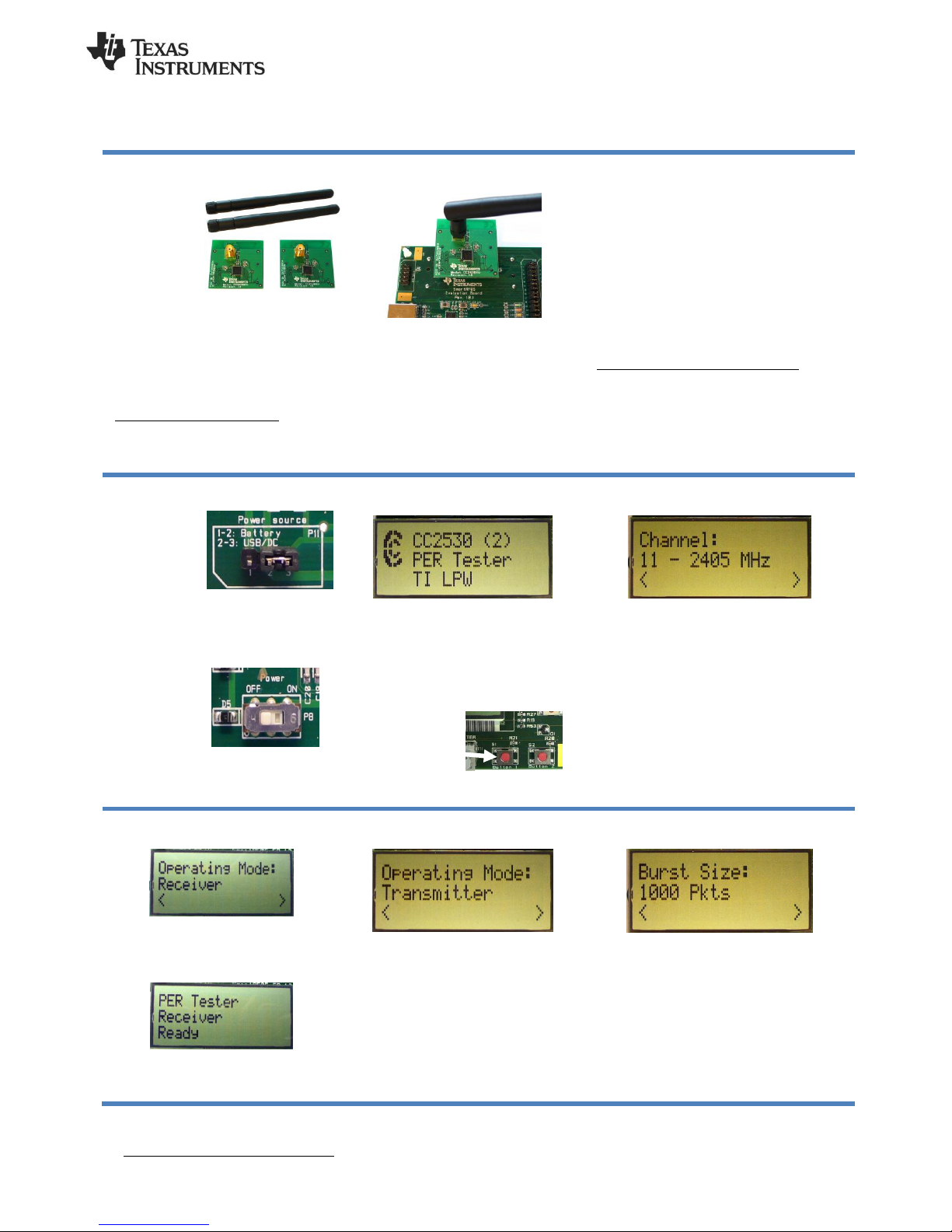
1. Kit Contents
2 x Pulse W1010
Antennas
2 x CC2530EM
Documentation
The RF boards in this kit are FCC and IC
certified and tested to comply with
ETSI/R&TTE standards over
temperature from 0 to +35°C. The
antenna, W1010 from Pulse, is a ¼
wave dipole antenna with 2 dBi gain.
FCC/IC Regulatory Compliance
FCC Part 15 Class A Compliant
IC ICES-003 Class A Compliant
2. Plug EM into SmartRF05EB
The CC2530EM, with the antenna
mounted on the SMA connector, can be
plugged into a SmartRF05EB. The
SmartRF05EB is included in the CC2530
Development Kit [2].
Caution! The kit contains ESD sensitive
components. Handle with care to prevent
permanent damage.
3. Power Options
There are several ways of applying power to
the SmartRF05EB;
USB (5V through USB plug)
External Power Supply
(requirements below)
2 x 1.5V AA Non-Rechargeable Alkaline
Batteries
Voltage regulators on the SmartRF05EB will
set the on-board voltage to 3.3V.
External Power Supply1 Requirements:
Nom Voltage: 4 to 20 VDC
Max Current: 1500 mA
Efficiency Level V
Warning! To minimize risk of personal injury or
property damage, never use rechargeable
batteries to power the board.
4. Select Power Source
Locate the
power source
header P11
just above the
LCD on the
SmartRF05EB
Connect pins 1 and 2 if you are using
batteries to power the board. Connect
pins 2 and 3 if you are using USB or
external power supply.
Once you have
set P11, find
switch P8 just
next to the DC
jack on the
SmartRF05EB.
To power on
the board, flip the switch from “OFF” to
“ON”.
5. Packet Error Rate (PER)
When power is applied to the
SmartRF05EB, the preprogrammed PER
test on the CC2530 will start running.
The LCD will display the screen as shown
in the picture above. The number in the
parentheses is the revision of the
CC2530.
Press Button 1 to
continue.
6. Select Channel
Select one of the 16 IEEE 802.15.4 channels,
with channel number from 11 to 26 (2405-2480
MHz, 5 MHz channel spacing). Select the
same channel for both boards.
The channel is selected by moving the joystick
to the right or left.
Press Button 1 to confirm the selection.
7. Set up the Receiver
Set one of the boards to operate as
receiver. Use the joystick to select mode.
Confirm by pressing Button 1.
The receiver will now wait for packets
from the transmitter.
8. Set up the Transmitter
Set the other board to operate as
transmitter. Use the joystick to select
mode. Confirm the selection by pressing
Button 1.
On the transmitter node, additional
parameters have to be set. On the next
screen, select the TX output power (signal
strength). Use the joystick to select
between -3 dBm, 0 dBm or 4 dBm.
Confirm the selection with Button 1.
9. TX: Packets and Rate
Next, select burst size (number of packets to
send) by using the joystick, either 1000, 10K,
100K or 1M packets. Confirm the selection with
Button 1.
After selecting burst size, select packet rate;
100, 50, 20 or 10 packet per second. Confirm
the selection with Button 1.
1
When using an external power supply, make sure it meets the listed requirements in addition to complying with applicable regional
product regulatory and safety certification requirements such as UL, CSA, VDE, CCC, and PSE.
Page 2
SWRA275A
September 2013
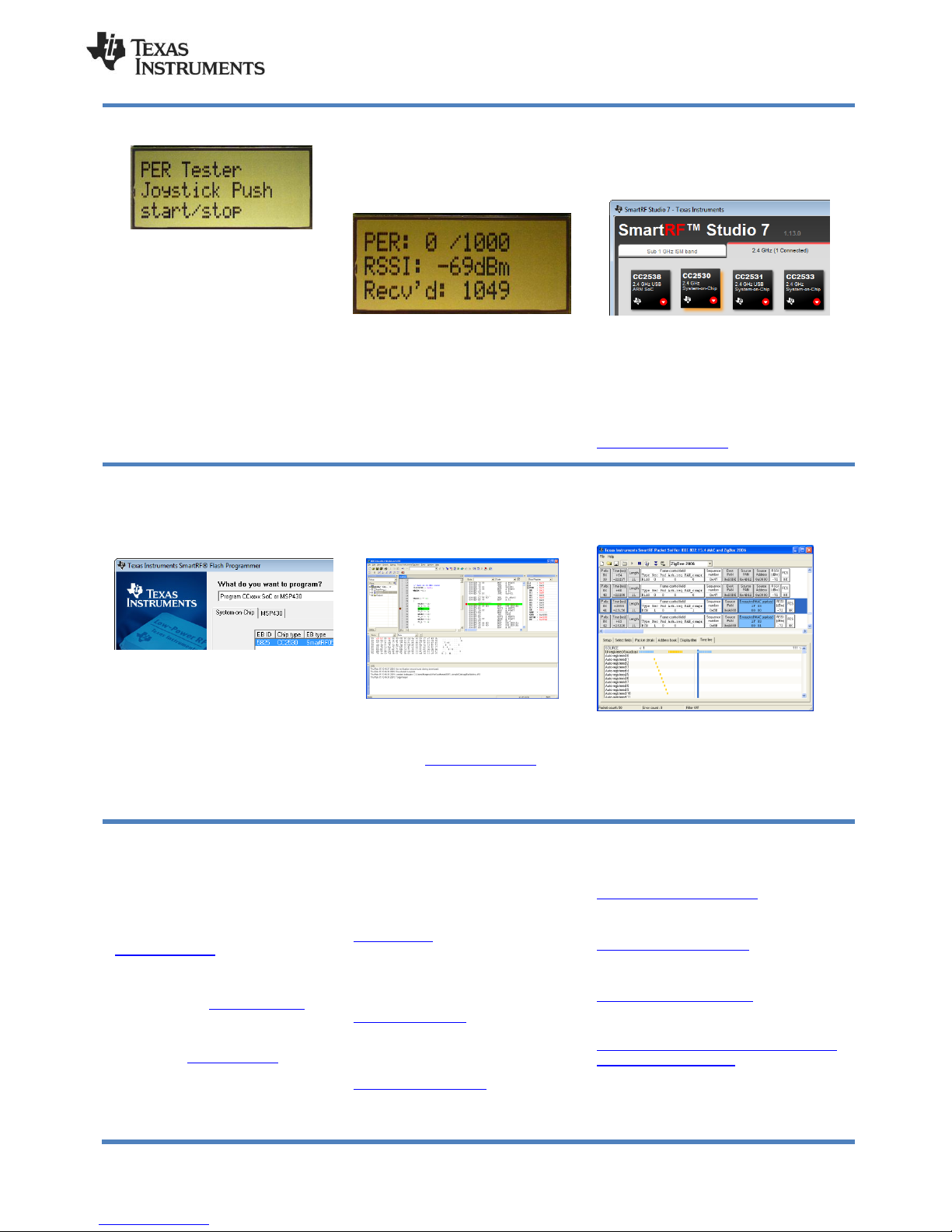
10. TX: Start PER Test
The transmitter is now configured for the
PER test. The PER test is started and
stopped by pushing the joystick (as a
button). The transmitter will display the
number of packets sent during the PER
test.
After stopping the test, it will start from
the beginning if the test is restarted.
11. RX: Observe PER
The PER test receiver will display the
PER value (number of lost and erroneous
packets divided by the number of packets
sent, displayed as a fraction of 1000).
The receiver will also display the number
of received packets and a moving
average RSSI value based on the last 32
packets.
By pressing button 1, all counters on the
receiver will be reset and the receiver will
restart the PER calculations.
12. SmartRF Studio
After running the PER test, the next
recommended step is to install SmartRF Studio
and to connect the evaluation board to the PC.
When installing SmartRF Studio, you will also
install the USB drivers required for the
SmartRF05EB board.
SmartRF Studio can be used for RF testing
and evaluation of C2530.
SmartRF Studio can be downloaded from
www.ti.com/smartrfstudio
13. Flash Programmer
Texas Instruments has a simple tool
which can be used to program the flash
on the CC2530.
The Flash Programmer application,
available on the kit web page [2], can be
used to program Intel HEX files, read the
contents of flash and several other
operations.
Programming of a CC2530 can be done
through the SmartRF05EB.
Production programming tools are
available from TI’s developer network [4].
14. IAR Embedded Workbench
To develop software, program and debug
the CC2530, you should use IAR
Embedded Workbench for 8051.
A free evaluation version of IAR EW8051
is included in the kit. A free, code size
limited version can be downloaded from
the web. See www.iar.com/ew8051.
15. Packet Sniffer
In order to debug RF protocols, it is possible to
use TI’s SmartRF Packet Sniffer.
You can use the CC2531 USB dongle or the
SmartRF05EB with a CC2530EM to capture
the packets.
A. Available Software
CC2530 Software Examples
Source code for the PER test and other
simple examples for the CC2530 [1]
Z-Stack™ Software
TI’s ZigBee-compliant protocol stack
www.ti.com/z-stack
RemoTI™ Network Protocol
TIs’ implementation of the ZigBee
RF4CE standard: www.ti.com/remoti
TIMAC Software
TI’s IEEE 802.15.4 medium-accesscontrol stack: www.ti.com/timac
B. More information
On Texas Instruments’ Low-Power RF
web site you will find all our latest
products, application and design notes,
FAQ section, news and events updates,
and much more. Just go to
www.ti.com/lprf
The Low Power RF Online Community
has forums, blogs and videos. Use the
forums to find information, discuss and
get help with your design. Join us at
www.ti.com/lprf-forum
The TI LPRF eNewsletter keeps you up to
date on e.g. new products, application
notes, software and events. Sign up at
www.ti.com/lprfnewsletter
C. References
[1] CC2530 product web page
www.ti.com/product/cc2530
[2] CC2530 Development Kit
www.ti.com/tool/cc2530dk
[3] SmartRF05EB User’s Guide
www.ti.com/lit/pdf/swru210
[4] LPRF Developer’s Network
http://focus.ti.com/general/docs/genconte
nt.tsp?contentId=98994
Page 3

IMPORTANT NOTICE
Texas Instruments Incorporated and its subsidiaries (TI) reserve the right to make corrections, enhancements, improvements and other
changes to its semiconductor products and services per JESD46, latest issue, and to discontinue any product or service per JESD48, latest
issue. Buyers should obtain the latest relevant information before placing orders and should verify that such information is current and
complete. All semiconductor products (also referred to herein as “components”) are sold subject to TI’s terms and conditions of sale
supplied at the time of order acknowledgment.
TI warrants performance of its components to the specifications applicable at the time of sale, in accordance with the warranty in TI’s terms
and conditions of sale of semiconductor products. Testing and other quality control techniques are used to the extent TI deems necessary
to support this warranty. Except where mandated by applicable law, testing of all parameters of each component is not necessarily
performed.
TI assumes no liability for applications assistance or the design of Buyers’ products. Buyers are responsible for their products and
applications using TI components. To minimize the risks associated with Buyers’ products and applications, Buyers should provide
adequate design and operating safeguards.
TI does not warrant or represent that any license, either express or implied, is granted under any patent right, copyright, mask work right, or
other intellectual property right relating to any combination, machine, or process in which TI components or services are used. Information
published by TI regarding third-party products or services does not constitute a license to use such products or services or a warranty or
endorsement thereof. Use of such information may require a license from a third party under the patents or other intellectual property of the
third party, or a license from TI under the patents or other intellectual property of TI.
Reproduction of significant portions of TI information in TI data books or data sheets is permissible only if reproduction is without alteration
and is accompanied by all associated warranties, conditions, limitations, and notices. TI is not responsible or liable for such altered
documentation. Information of third parties may be subject to additional restrictions.
Resale of TI components or services with statements different from or beyond the parameters stated by TI for that component or service
voids all express and any implied warranties for the associated TI component or service and is an unfair and deceptive business practice.
TI is not responsible or liable for any such statements.
Buyer acknowledges and agrees that it is solely responsible for compliance with all legal, regulatory and safety-related requirements
concerning its products, and any use of TI components in its applications, notwithstanding any applications-related information or support
that may be provided by TI. Buyer represents and agrees that it has all the necessary expertise to create and implement safeguards which
anticipate dangerous consequences of failures, monitor failures and their consequences, lessen the likelihood of failures that might cause
harm and take appropriate remedial actions. Buyer will fully indemnify TI and its representatives against any damages arising out of the use
of any TI components in safety-critical applications.
In some cases, TI components may be promoted specifically to facilitate safety-related applications. With such components, TI’s goal is to
help enable customers to design and create their own end-product solutions that meet applicable functional safety standards and
requirements. Nonetheless, such components are subject to these terms.
No TI components are authorized for use in FDA Class III (or similar life-critical medical equipment) unless authorized officers of the parties
have executed a special agreement specifically governing such use.
Only those TI components which TI has specifically designated as military grade or “enhanced plastic” are designed and intended for use in
military/aerospace applications or environments. Buyer acknowledges and agrees that any military or aerospace use of TI components
which have not been so designated is solely at the Buyer's risk, and that Buyer is solely responsible for compliance with all legal and
regulatory requirements in connection with such use.
TI has specifically designated certain components as meeting ISO/TS16949 requirements, mainly for automotive use. In any case of use of
non-designated products, TI will not be responsible for any failure to meet ISO/TS16949.
Products Applications
Audio www.ti.com/audio Automotive and Transportation www.ti.com/automotive
Amplifiers amplifier.ti.com Communications and Telecom www.ti.com/communications
Data Converters dataconverter.ti.com Computers and Peripherals www.ti.com/computers
DLP® Products www.dlp.com Consumer Electronics www.ti.com/consumer-apps
DSP dsp.ti.com Energy and Lighting www.ti.com/energy
Clocks and Timers www.ti.com/clocks Industrial www.ti.com/industrial
Interface interface.ti.com Medical www.ti.com/medical
Logic logic.ti.com Security www.ti.com/security
Power Mgmt power.ti.com Space, Avionics and Defense www.ti.com/space-avionics-defense
Microcontrollers microcontroller.ti.com Video and Imaging www.ti.com/video
RFID www.ti-rfid.com
OMAP Applications Processors www.ti.com/omap TI E2E Community e2e.ti.com
Wireless Connectivity www.ti.com/wirelessconnectivity
Mailing Address: Texas Instruments, Post Office Box 655303, Dallas, Texas 75265
Copyright © 2016, Texas Instruments Incorporated
 Loading...