

1. Kit Contents
2. Hardware Requirements
3. SmartRF05 Board Setup
4. Power Options
6. Select Channel
7. Select Mode
CC2530-CC2592EM Development Kit Quick Start Guide
Opening the Box and Running the Packet Error Rate Test
• 2 x CC2530-CC2592 EM
• 2 x 2.4GHz Antennas
• Documentation
Caution! The kit
contains ESD sensitive
components. Handle with
care to prevent
permanent damage.
Set the EM Selection switch in the
position SOC/TRX.
For best performance, it is recommended
to turn off the RS232 interface.
5. Packet Error Rate Setup
The CC2530-CC2592EM is an add-on
module that can be plugged onto a
SmartRF05EB. To run the example in this
Quick Start Guide, two SmartRF05 boards
are required to establish an RF link
between the evaluation modules.
More information about SmartRF05EB can
be found here: www.ti.com/lit/pdf/swru210
There are a few ways of applying power to
the SmartRF05 board.
• 2 x 1.5V AA Alkaline Batteries
• USB
• External Power Supply
For the batteries and USB, there are
voltage regulators on the SmartRF05
board that will set the on-board voltage to
3.3V. The external power supply should
set a voltage that does not exceed 3.3V.
Note that there should be only one
active power source at any given time.
The CC2530-CC2592EM can also be plugged
into the SmartRF05 battery boards for
standalone applications.
Select power source with jumper on header
P11:
• Position 1-2 Batteries
• Position 2-3 USB or DC supply.
Once P11 is set, locate P8 switch on
Smart05EB to power up the board.
After power up, the preloaded PER test
application on the CC2530 will start. The
LCD will display the screen as shown in
the picture above. The number in the
parentheses is the revision of the
CC2530. Press Button S1 to enter the
menu.
Note: if you don’t see anything on the
screen make sure the board is
correctly powered (see step 5 and 6
above).
Select a channel between 11 and 26
(2405- 2480 MHz). The channel is
selected by navigating the joystick to the
right or left. Confirm the selection by
pressing Button S1.
Web sites:
E2E Forum:
www.ti.com/lprf
www.ti.com/lprf-forum
Select receiver on one of the SmartRF05EB’s
and transmitter on the other. Use the joystick
to select mode. Confirm the selection by
pressing Button S1.
Make sure to subscribe to the Low-Power RF
Newsletter to receive information about
updates to documentation, new product
releases, and more. Sign up on the TI web
pages.
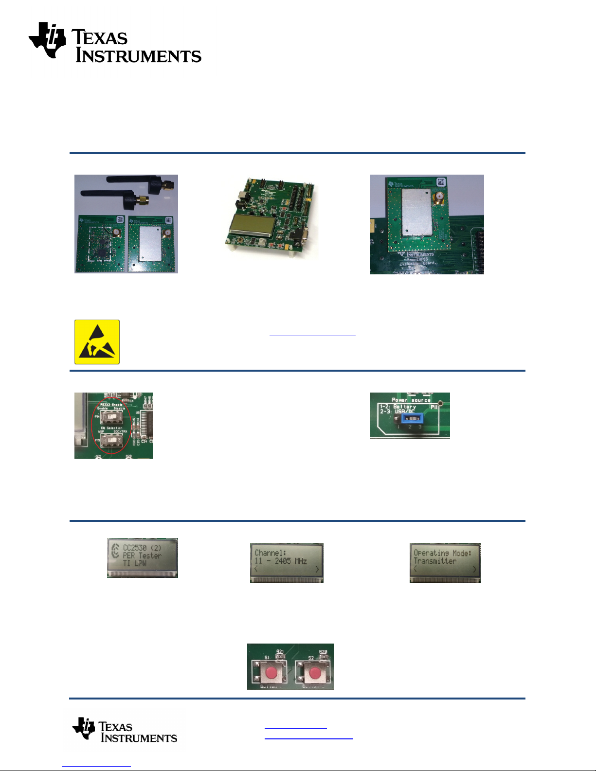
8. RX: Select Gain
9. TX: Select Output Power
10. TX: Select # of Packets
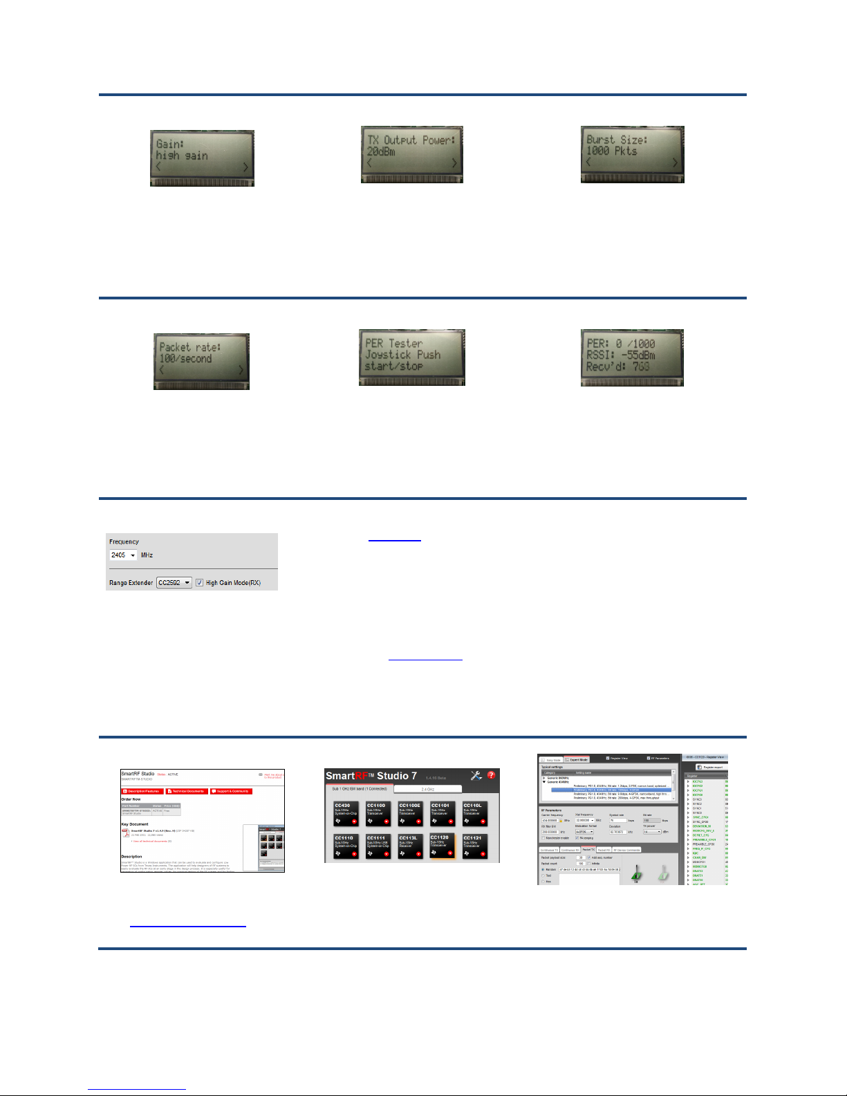
12. TX: Start PER Test
13. Display PER
I
nformation
15. References
16. Troubleshooting
1. Download and Install
2. Launch SmartRF Studio
3. Test the Radio
For the receiver select LNA gain on the
CC2592 with the joystick. Either high gain
or low gain mode are possible settings.
Normally, high gain mode should be
selected. Confirm the selection with
Button S1. The receiver is now ready to
receive packets.
11. TX: Select Packet Rate
Select packet rate (number of packets
transmitted per second) on the
transmitter. Confirm the selection with
Button S1.
14. SmartRF Studio
SmartRF® Studio supports the CC2530CC2592. When the board is connected to
the SmartRF05EB, it is possible to tick
the CC2591 box in the “Range Extender”
pane.
Studio will then make sure that I/O on the
CC2530 is set up for proper control of the
CC2592.
On the transmitter node, select the TX
output power (signal strength).Use the
joystick (move right or left) to select the
output power in dBm. Confirm the
selection with Button S1.
The transmitter is now configured for the
PER test. The PER test is started by
pushing the joystick (as a button). The
transmitter will display the number of
packets sent during the PER test. The
PER test is stopped by pushing the
joystick again.
Please visit www.ti.com and
http://www.ti.com/tool/
On the kit product page, you will find
additional documentation, links to updated
software examples and software tools like
SmartRF Studio.
You will also find a lot of information on the
TI E2E forum at http://e2e.ti.com
We hope that you will enjoy working
with the CC2530-CC2592 combo
design.
Select burst size (number of packets to send)
by moving the joystick right or left. Confirm the
selection with Button S1.
The PER test receiver will display the PER
value (number of lost and erroneous packets
divided by the total number of packets sent,
displayed as a fraction of 1000). It will also
display a moving average RSSI value
(received signal strength). The test can be
reset by pressing Button S1.
It you are experiencing problems with this test,
please check the following:
• Nothing is shown in the display! Make
sure the board is powered correctly.
Please visit the kit web page and check for
updated SW and documentation.
Before connecting SmartRF05EB to your
PC, download and install SmartRF Studio
from www.ti.com/smartrfstudio.
After installing the tool, connect the EB
to the PC using the USB cable and start
SmartRF Studio. Select the “2.4 GHz”
tab and double click the highlighted
CC2530 device icon.
You can now configure the radio, run
performance tests, export register settings
and run link tests with another CC2530 on a
SmartRF05EB connected to the PC.

IMPORTANT NOTICE FOR TI REFERENCE DESIGNS
Texas Instruments Incorporated ("TI") reference designs are solely intended to assist designers (“Buyers”) who are developing systems that
incorporate TI semiconductor products (also referred to herein as “components”). Buyer understands and agrees that Buyer remains
responsible for using its independent analysis, evaluation and judgment in designing Buyer’s systems and products.
TI reference designs have been created using standard laboratory conditions and engineering practices. TI has not conducted any
testing other than that specifically described in the published documentation for a particular reference design. TI may make
corrections, enhancements, improvements and other changes to its reference designs.
Buyers are authorized to use TI reference designs with the TI component(s) identified in each particular reference design and to modify the
reference design in the development of their end products. HOWEVER, NO OTHER LICENSE, EXPRESS OR IMPLIED, BY ESTOPPEL
OR OTHERWISE TO ANY OTHER TI INTELLECTUAL PROPERTY RIGHT, AND NO LICENSE TO ANY THIRD PARTY TECHNOLOGY
OR INTELLECTUAL PROPERTY RIGHT, IS GRANTED HEREIN, including but not limited to any patent right, copyright, mask work right,
or other intellectual property right relating to any combination, machine, or process in which TI components or services are used.
Information published by TI regarding third-party products or services does not constitute a license to use such products or services, or a
warranty or endorsement thereof. Use of such information may require a license from a third party under the patents or other intellectual
property of the third party, or a license from TI under the patents or other intellectual property of TI.
TI REFERENCE DESIGNS ARE PROVIDED "AS IS". TI MAKES NO WARRANTIES OR REPRESENTATIONS WITH REGARD TO THE
REFERENCE DESIGNS OR USE OF THE REFERENCE DESIGNS, EXPRESS, IMPLIED OR STATUTORY, INCLUDING ACCURACY OR
COMPLETENESS. TI DISCLAIMS ANY WARRANTY OF TITLE AND ANY IMPLIED WARRANTIES OF MERCHANTABILITY, FITNESS
FOR A PARTICULAR PURPOSE, QUIET ENJOYMENT, QUIET POSSESSION, AND NON-INFRINGEMENT OF ANY THIRD PARTY
INTELLECTUAL PROPERTY RIGHTS WITH REGARD TO TI REFERENCE DESIGNS OR USE THEREOF. TI SHALL NOT BE LIABLE
FOR AND SHALL NOT DEFEND OR INDEMNIFY BUYERS AGAINST ANY THIRD PARTY INFRINGEMENT CLAIM THAT RELATES TO
OR IS BASED ON A COMBINATION OF COMPONENTS PROVIDED IN A TI REFERENCE DESIGN. IN NO EVENT SHALL TI BE
LIABLE FOR ANY ACTUAL, SPECIAL, INCIDENTAL, CONSEQUENTIAL OR INDIRECT DAMAGES, HOWEVER CAUSED, ON ANY
THEORY OF LIABILITY AND WHETHER OR NOT TI HAS BEEN ADVISED OF THE POSSIBILITY OF SUCH DAMAGES, ARISING IN
ANY WAY OUT OF TI REFERENCE DESIGNS OR BUYER’S USE OF TI REFERENCE DESIGNS.
TI reserves the right to make corrections, enhancements, improvements and other changes to its semiconductor products and services per
JESD46, latest issue, and to discontinue any product or service per JESD48, latest issue. Buyers should obtain the latest relevant
information before placing orders and should verify that such information is current and complete. All semiconductor products are sold
subject to TI’s terms and conditions of sale supplied at the time of order acknowledgment.
TI warrants performance of its components to the specifications applicable at the time of sale, in accordance with the warranty in TI’s terms
and conditions of sale of semiconductor products. Testing and other quality control techniques for TI components are used to the extent TI
deems necessary to support this warranty. Except where mandated by applicable law, testing of all parameters of each component is not
necessarily performed.
TI assumes no liability for applications assistance or the design of Buyers’ products. Buyers are responsible for their products and
applications using TI components. To minimize the risks associated with Buyers’ products and applications, Buyers should provide
adequate design and operating safeguards.
Reproduction of significant portions of TI information in TI data books, data sheets or reference designs is permissible only if reproduction is
without alteration and is accompanied by all associated warranties, conditions, limitations, and notices. TI is not responsible or liable for
such altered documentation. Information of third parties may be subject to additional restrictions.
Buyer acknowledges and agrees that it is solely responsible for compliance with all legal, regulatory and safety-related requirements
concerning its products, and any use of TI components in its applications, notwithstanding any applications-related information or support
that may be provided by TI. Buyer represents and agrees that it has all the necessary expertise to create and implement safeguards that
anticipate dangerous failures, monitor failures and their consequences, lessen the likelihood of dangerous failures and take appropriate
remedial actions. Buyer will fully indemnify TI and its representatives against any damages arising out of the use of any TI components in
Buyer’s safety-critical applications.
In some cases, TI components may be promoted specifically to facilitate safety-related applications. With such components, TI’s goal is to
help enable customers to design and create their own end-product solutions that meet applicable functional safety standards and
requirements. Nonetheless, such components are subject to these terms.
No TI components are authorized for use in FDA Class III (or similar life-critical medical equipment) unless authorized officers of the parties
have executed an agreement specifically governing such use.
Only those TI components that TI has specifically designated as military grade or “enhanced plastic” are designed and intended for use in
military/aerospace applications or environments. Buyer acknowledges and agrees that any military or aerospace use of TI components that
have not been so designated is solely at Buyer's risk, and Buyer is solely responsible for compliance with all legal and regulatory
requirements in connection with such use.
TI has specifically designated certain components as meeting ISO/TS16949 requirements, mainly for automotive use. In any case of use of
non-designated products, TI will not be responsible for any failure to meet ISO/TS16949.IMPORTANT NOTICE
Mailing Address: Texas Instruments, Post Office Box 655303, Dallas, Texas 75265
Copyright © 2015, Texas Instruments Incorporated
 Loading...