

Page 1

Z-Stack
User’s Guide For
CC2431ZDK
ZigBee 2006 Release
Version 1.4.3
Document Number: F8W-2006-0025
Texas Instruments, Inc.
San Diego, California USA
(619) 497-3845
i Copyright 2006-2007 Texas Instruments, Inc. All rights reserved.
Page 2

Z-Stack User's Guide - CC2431ZDK F8W-2006-0025 Version 1.4.3
Revision Description Date
1.0 Initial release. 12/13/2006
1.1 Changed IAR compiler version to 7.30B in Section 4.2. 12/21/2007
i Copyright 2006-2007 Texas Instruments, Inc. All rights reserved.
Page 3

Z-Stack User's Guide - CC2431ZDK F8W-2006-0025 Version 1.4.3
Table of Contents
1. INTRODUCTION................................................................................................................. 1
1.1. SCOPE .............................................................................................................................. 1
1.2. SCOPE .............................................................................................................................. 1
2. PRODUCT PACKAGE DESCRIPTION........................................................................... 1
2.1. INSTALLATION PACKAGE CONTENTS ............................................................................... 1
2.2. DEVELOPMENT BOARDS .................................................................................................. 1
2.3. CABLES............................................................................................................................ 2
3. INSTALLATION REQUIREMENTS................................................................................ 2
3.1. HOST COMPUTER REQUIREMENTS ................................................................................... 2
3.2. TARGET DEVELOPMENT SYSTEM REQUIREMENTS ........................................................... 3
4. PRODUCT INSTALLATION PROCEDURES ................................................................ 3
4.1. INSTALL Z-STACK PACKAGE ........................................................................................... 3
INSTALL IAR EW8051 PACKAGE ........................................................................................ 3
4.2................................................................................................................................................ 3
4.3. DEVICE IEEE ADDRESSES ............................................................................................... 3
5. CONFIGURING AND USING Z-STACK ......................................................................... 3
5.1. CONFIGURING Z-STACK................................................................................................... 3
5.2. LOGICAL DEVICE TYPES .................................................................................................. 4
5.3. SELECTING THE APPLICATION PROFILE............................................................................ 4
5.4. BUILDING THE SAMPLE DEVICES ..................................................................................... 4
5.5. BUILDING A LOCATION DONGLE COORDINATOR DEVICE ................................................ 4
5.6. BUILDING A REFERENCE NODE ROUTER DEVICE ............................................................. 8
5.7. BUILDING A BLIND NODE ROUTER DEVICE ................................................................... 11
6. Z-LOCATION DEMONSTRATION ............................................................................... 14
6.1. SWITCHES AND LEDS .................................................................................................... 14
6.2. INITIAL LOADING OF 64-BIT IEEE ADDRESS ................................................................. 15
6.3. NON-VOLATILE MEMORY.............................................................................................. 15
6.4. RUNNING THE SAMPLE APPLICATIONS........................................................................... 15
7. CHANNEL SELECTION .................................................................................................. 16
7.1. ENERGY LEVEL .............................................................................................................. 17
APPLICABLE DOCUMENTS.................................................................................................. 17
ii Copyright 2006-2007 Texas Instruments, Inc. All rights reserved.
Page 4

Z-Stack User's Guide - CC2431ZDK F8W-2006-0025 Version 1.4.3
Table of Figures
FIGURE 1: CHIPCON SMARTRF04EB WITH CC243XEM ................................................................. 1
FIGURE 2: CHIPCON SOC_BB BATTERY BOARD WITH CC243XEM................................................ 2
Table of Tables
TABLE 1: DEFAULT CHANNEL SELECT BIT MAP ........................................................................... 16
iii Copyright 2006-2007 Texas Instruments, Inc. All rights reserved.
Page 5
Z-Stack User's Guide - CC2431ZDK F8W-2006-0025 Version 1.4.3
1. Introduction
1.1. Scope
This document accompanies the Texas Instruments Z-Location Z-Stack™ Development kit and
is essentially the same as the document that accompanies the basic Texas Instruments Z-Stack
Development kit: The Z-Stack User’s Guide – CC2430ZDK. The primary difference is that this
document uses Z-Location as the sample application. Z-Location is a sophisticated radio location
solution built on top of Z-Stack, conforming to ZigBee Alliance standards (www.zigbee.org).
1.2. Scope
The CC2430EM and the CC2431EM are interchangeable, except that a device intended to run as
a Blind Node must be fitted with the CC2431EM.
2. Product Package Description
2.1. Installation Package Contents
The downloaded Z-Stack installation package contains all of the documentation and software
required to install, configure, and develop applications using Z-Stack. The package employs a
Microsoft Windows-based installation application which guides the installation process.
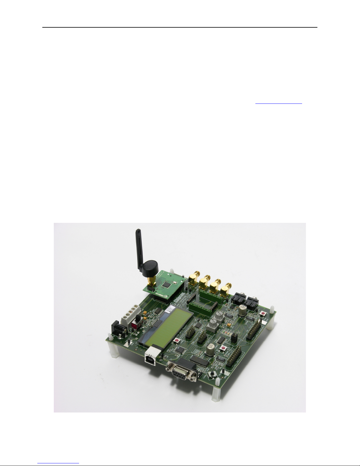
2.2. Development Boards
There are two Chipcon SmartRF04EB evaluation boards, each to be fitted with a CC243xEM
evaluation module.
Figure 1: Chipcon SmartRF04EB with CC243xEM
1 Copyright 2006-2007 Texas Instruments, Inc. All rights reserved.
Page 6
Z-Stack User's Guide - CC2431ZDK F8W-2006-0025 Version 1.4.3
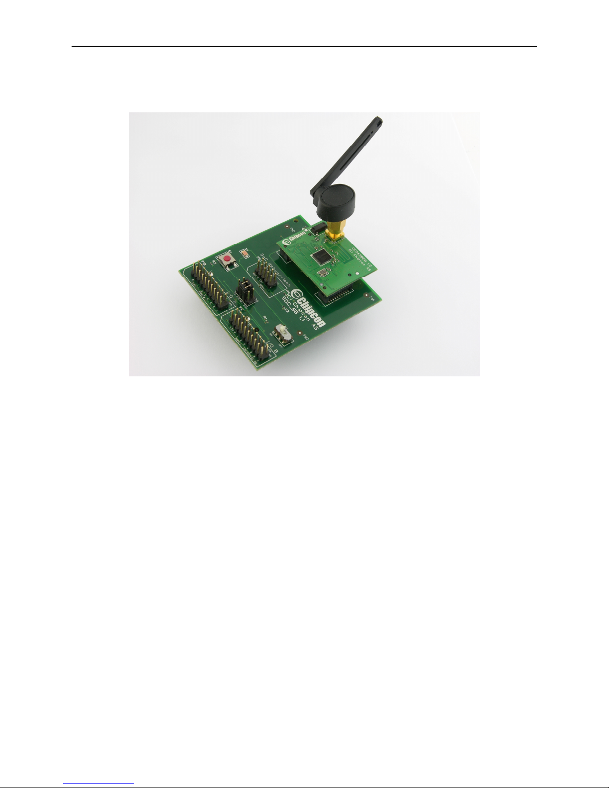
There are ten compact Chipcon SOC_BB evaluation boards, each to be fitted with a CC243xEM.
Figure 2: Chipcon SOC_BB Battery Board with CC243xEM
2.3. Cables
All necessary cabling has been included with the development kit. To support program download
and debugging on the SmartRF04EB, a USB cable must be connected from the target board to
the host PC. An RS232 cable may be connected between the serial port on the SmartRF04EB (9pin connector) and the host PC to enable communication with the Z-Tool or Z-Location PC
application included with the Z-Stack package.
3. Installation Requirements
3.1. Host Computer Requirements
Z-Stack and Z-Tool are designed for installation on a personal computer running Microsoft
Windows XP Professional or Windows 2000. The following are the minimum requirements for
the platform hosting Z-Stack and Z-Tool:
• .NET 1.1 Framework
• Windows XP Service Pack 1 (if using Windows XP)
• 1 serial port for Z-Tool communication with the SmartRF04EB board
• 1 USB port for download/debug of SmartRF04EB boards
2 Copyright 2006-2007 Texas Instruments, Inc. All rights reserved.
Page 7

Z-Stack User's Guide - CC2431ZDK F8W-2006-0025 Version 1.4.3
3.2. Target Development System Requirements
Z-Stack provides a complementary offering to the IAR Embedded Workbench (EW8051) suite
of software development tools. These tools support project management, compiling, assembling,
linking, downloading, and debugging for various 8051-based processors, including the Chipcon
CC243x family. The following is required support for the Z-Stack target development system:
• IAR EW8051 ( http://www.iar.com/ )
4. Product Installation Procedures
4.1. Install Z-Stack Package
Install the Texas Instruments Z-Stack files and programs from the downloaded package. Run the
windows-based installation program, ZStack-CC2430-1.4.3-1.2.0.exe, to create the required
directory structure and load all software and documentation files. Review the README.txt file
for a synopsis of new features and changes with this Z-Stack release.
4.2. Install IAR EW8051 Package
Install the Embedded Workbench for 8051 from IAR Systems: http://www.iar.com/. The project
and library files included in this release of Z-Stack require the use of EW8051 version 7.30B or
newer. When considering an upgrade to a newer version of EW8051, it is necessary to verify that
installed project and library files are compatible with the newer development tools.
4.3. Device IEEE Addresses
Each CC243xEM board in the development kit has been pre-programmed with a unique 64-bit
IEEE address. These addresses, assigned by Chipcon, are stored in Little-Endian format, located
in the upper 8 bytes of FLASH memory on the CC243x processor. The IEEE address is
displayed on a sticker affixed to the bottom of each CC243xEM.
This FLASH memory location would also be used for factory commissioning of IEEE addresses
on devices that use Z-Stack. For CC243x-F128 devices, used on all boards in the development
kit, the least significant byte of the IEEE address is located at “linear” FLASH memory address
0x1FFF8, corresponding to “banked” address 0x3FFF8.
Z-Stack treats the IEEE address area of FLASH as “write once” memory. When an attempt is
made to write an IEEE address to that location (via Z-Tool, etc.), it will succeed only if the
current contents are empty (0xFFFFFFFFFFFFFFFF). In other words, any 8-byte pattern other
than all 0xFF values, is considered to be a valid IEEE address and won’t be modified.
5. Configuring and Using Z-Stack
5.1. Configuring Z-Stack
For the purposes of this release, the Logical Device Type and Profile are pre-configured. Details
on configuring and programming the sample applications for the Z-Location are provided in the
sections beginning with “Building the Sample Devices”.
3 Copyright 2006-2007 Texas Instruments, Inc. All rights reserved.
Page 8

Z-Stack User's Guide - CC2431ZDK F8W-2006-0025 Version 1.4.3
5.2. Logical Device Types
Z-Stack can be configured in one of three ways:
• ZigBee Coordinator – This device is configured to start the IEEE 802.15.4 network and
will serve as the PAN Coordinator in that network.
• ZigBee Router – This device is configured to join an existing network, associate to a
Coordinator or Router, and then allow other devices to associate to it. It will route data
packets in the network .
• ZigBee End Device – This device is configured to join an existing network and will
associate with a Coordinator or Router.
5.3. Selecting the Application Profile
Once the Logical Device Type has been selected, devices can be configured for an application.
Supported sample applications for this release of Z-Location include:
• Location Profile – Dongle
• Location Profile – Reference Node
• Location Profile – Blind Node
Multiple application profiles can be configured on a ZigBee device. Profiles are configured to
operate overtop Endpoints which provide unique addressing for the application. By convention,
Endpoint 0 is reserved for the ZigBee Device Object, which performs device specific processing
and implements functions required to support the selected Logical Device Type.
5.4. Building the Sample Devices
The remainder of this document describes setting up a network with 6 or more nodes: a Location
Dongle as Coordinator, 4 or more Reference Node Routers, and 1 or more Blind Node Router(s).
Notice that the procedures in Sections 5.5 thru 5.7 are identical, only folder names and filenames
are different. Other Z-Location sample applications (e.g. a Blind Node End Device) can be built
and loaded using the same general procedures.
5.5. Building a Location Dongle Coordinator Device
• Make sure all tools have been installed (Sections 4.1 – 4.2)
4 Copyright 2006-2007 Texas Instruments, Inc. All rights reserved.
Page 9

Z-Stack User's Guide - CC2431ZDK F8W-2006-0025 Version 1.4.3
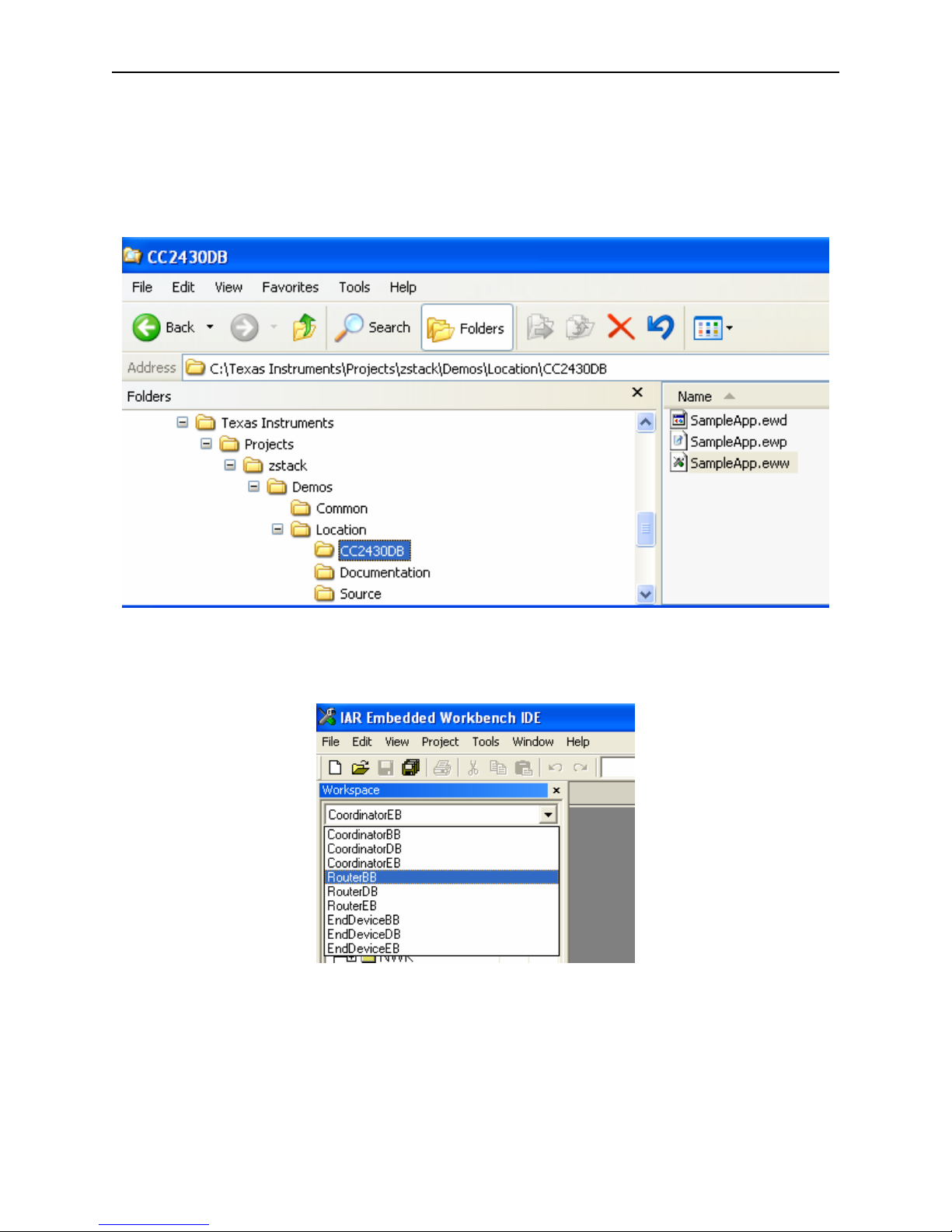
• Navigate to the SampleApp project directory and launch the IAR Embedded Workshop
by double clicking on the SampleApp.eww file.
• Select the CoordinatorEB project from the Workspace pull-down menu:
5 Copyright 2006-2007 Texas Instruments, Inc. All rights reserved.
Page 10

Z-Stack User's Guide - CC2431ZDK F8W-2006-0025 Version 1.4.3
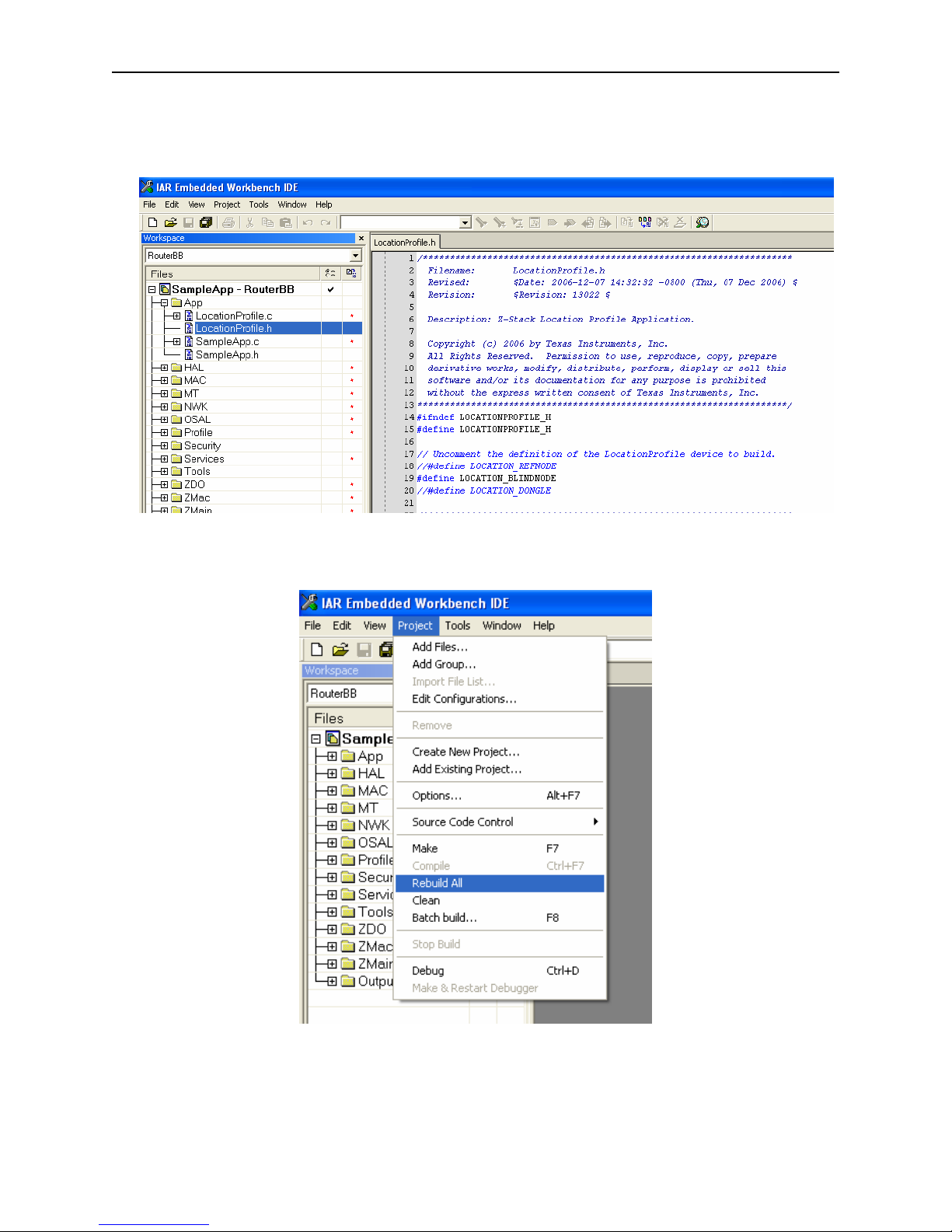
• Open LocationProfile.h file by clicking the ‘+’ next to the folder ‘App’ and then double-
clicking on the file name. Uncomment only the line that defines the Location Dongle.
• Build the application by pulling down the Project menu and clicking on Rebuild All:
6 Copyright 2006-2007 Texas Instruments, Inc. All rights reserved.
Page 11
Z-Stack User's Guide - CC2431ZDK F8W-2006-0025 Version 1.4.3
• Install a CC243xEM onto a SmartRF04EB and connect the SmartRF04EB to the
development PC with a USB cable. Apply power by moving switch S3 toward the
CC243xEM. If Windows needs to install a driver, browse to C:\Program Files\IAR
Systems\Embedded Workbench 4.0\8051\drivers\Chipcon to locate the necessary files.
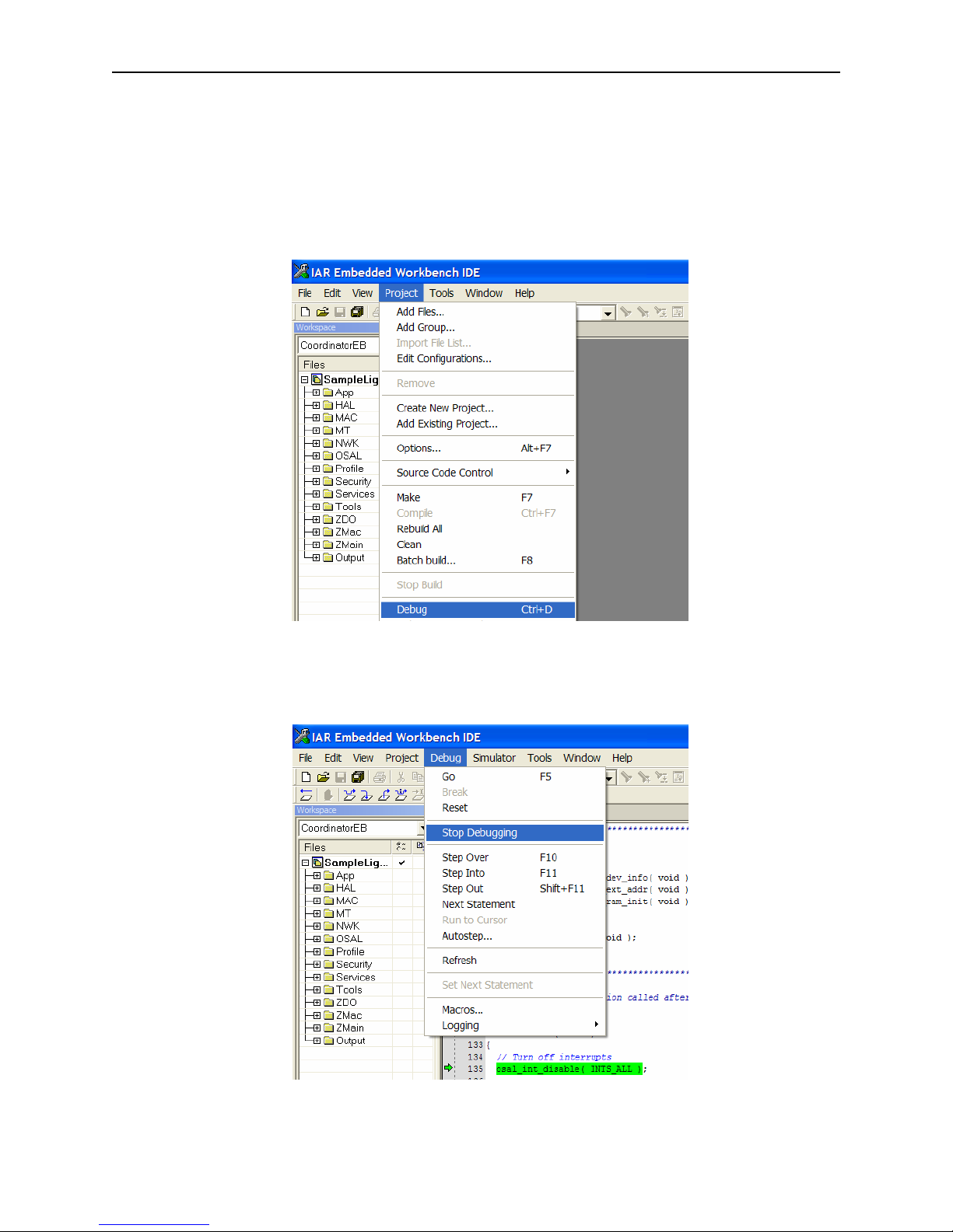
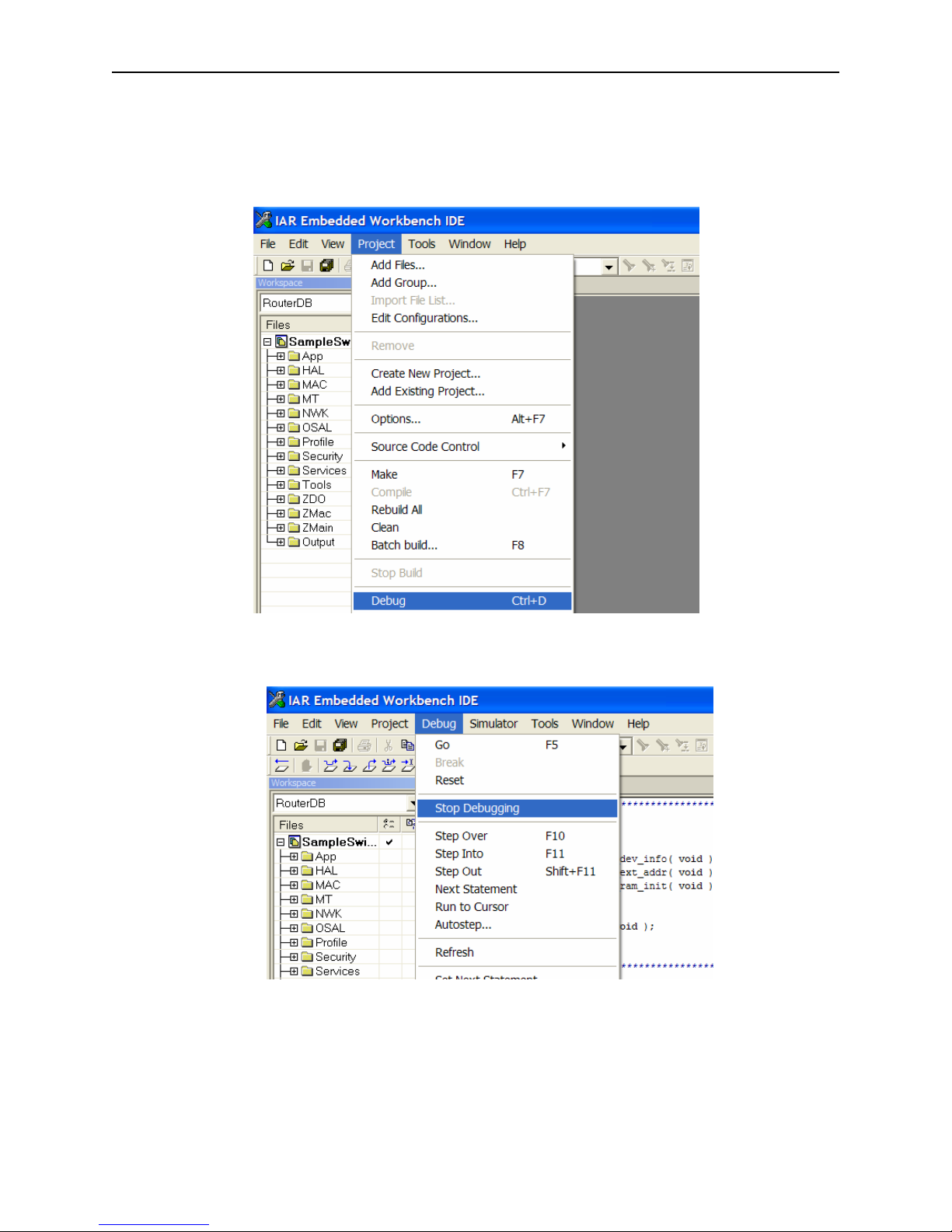
• Download the application by pulling down the Project menu and clicking on Debug.
• After downloading to the SmartRF04EB is complete, exit the debugger by pulling down
the Debug menu and clicking on Stop Debugging. Exit the Embedded Workbench IDE.
7 Copyright 2006-2007 Texas Instruments, Inc. All rights reserved.
Page 12

Z-Stack User's Guide - CC2431ZDK F8W-2006-0025 Version 1.4.3
• Remove power from the CC2430EB by moving switch S3 away from the CC2430EM.
Disconnect the board from the USB cable and set it aside.
5.6. Building a Reference Node Router Device
• Make sure all tools have been installed (Sections 4.1 – 4.2)
• Navigate to the SampleApp project directory and launch the IAR Embedded Workshop
by double clicking on the SampleApp.eww file:
• Select the RouterBB project from the Workspace pull-down menu:
8 Copyright 2006-2007 Texas Instruments, Inc. All rights reserved.
Page 13

Z-Stack User's Guide - CC2431ZDK F8W-2006-0025 Version 1.4.3
• Open the LocationProfile.h file by clicking the ‘+’ next to the folder ‘App’ and then
double-clicking on the file name. Uncomment only the line that defines the Reference Node.
• Build the application by pulling down the Project menu and clicking on Rebuild All:
9 Copyright 2006-2007 Texas Instruments, Inc. All rights reserved.
Page 14

Z-Stack User's Guide - CC2431ZDK F8W-2006-0025 Version 1.4.3
• Install a CC243xEM onto a SmartRF04EB and connect the SmartRF04EB to the
development PC with a USB cable. Apply power by moving switch S3 toward the
CC2431EM. If Windows needs to install a driver, browse to C:\Program Files\IAR
Systems\Embedded Workbench 4.0\8051\drivers\Chipcon to locate the necessary files.
• Download the application by pulling down the Project menu and clicking on Debug:
• After downloading to the CC2430EB is complete, exit the debugger by pulling down the
Debug menu and clicking on Stop Debugging:
• If one or more additional Reference Node Router devices are to be programmed, repeat
the previous three steps, starting with installation of a different CC243xEM onto the
SmartRF04EB .
10 Copyright 2006-2007 Texas Instruments, Inc. All rights reserved.
Page 15
Z-Stack User's Guide - CC2431ZDK F8W-2006-0025 Version 1.4.3
5.7. Building a Blind Node Router Device
• Make sure all tools have been installed (Sections 4.1 – 4.2)
• Navigate to the SampleApp project directory and launch the IAR Embedded Workshop
by double clicking on the SampleApp.eww file:
• Select the RouterBB project from the Workspace pull-down menu:
11 Copyright 2006-2007 Texas Instruments, Inc. All rights reserved.
Page 16
Z-Stack User's Guide - CC2431ZDK F8W-2006-0025 Version 1.4.3
• Open the LocationProfile.h file by clicking the ‘+’ next to the folder ‘App’ and then
double-clicking on the file name. Uncomment only the line that defines the Blind Node.
• Build the application by pulling down the Project menu and clicking on Rebuild All:
• Install a CC2431EM onto a SmartRF04EB and connect the SmartRF04EB to the
development PC with a USB cable. Apply power by moving switch S3 toward the
12 Copyright 2006-2007 Texas Instruments, Inc. All rights reserved.
Page 17
Z-Stack User's Guide - CC2431ZDK F8W-2006-0025 Version 1.4.3
CC2431EM. If Windows needs to install a driver, browse to C:\Program Files\IAR
Systems\Embedded Workbench 4.0\8051\drivers\Chipcon to locate the necessary files.
• Download the application by pulling down the Project menu and clicking on Debug:
• After downloading to the CC2430EB is complete, exit the debugger by pulling down the
Debug menu and clicking on Stop Debugging:
• If one or more additional Reference Node Router devices are to be programmed, repeat
the previous three steps, starting with installation of a different CC2431EM onto the
SmartRF04EB .
• When all devices have been programmed, exit the Embedded Workbench IDE.
13 Copyright 2006-2007 Texas Instruments, Inc. All rights reserved.
Page 18
Z-Stack User's Guide - CC2431ZDK F8W-2006-0025 Version 1.4.3
6. Z-Location Demonstration
6.1. Switches and LEDs
In this, and other Z-Stack documents, references are made to switches and LEDs located on
evaluation boards. These devices are used to control certain Z-Stack features and display status.
Certain procedures require user input via switches, commonly referred to as SW1 through SW5.
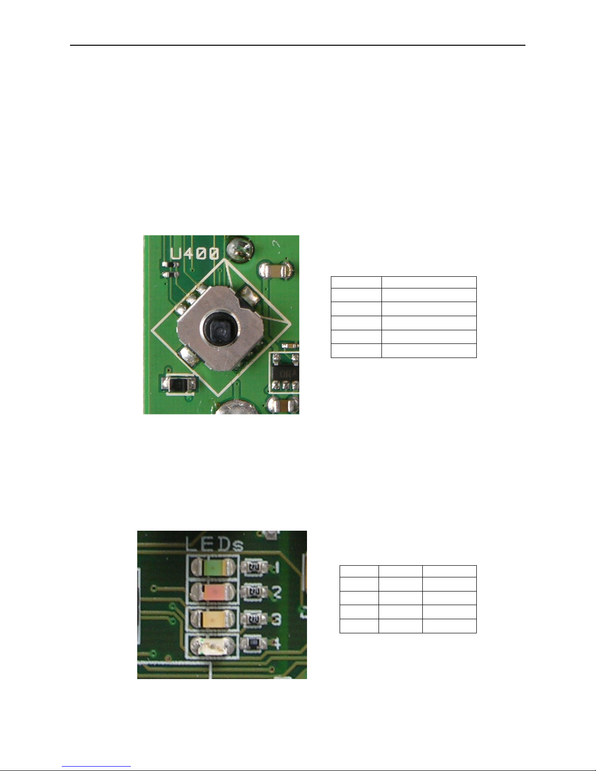
The SmartRF04EB boards have a 5-position joystick, designated U400, which provides these
switch inputs as shown in the table below. Pressing the joystick toward the U400 label (up
position) activates the SW1 input. Switch inputs SW2 – SW4 result from pressing the joystick to
the right, down (away from U400), and left positions, respectively. SW5 occurs when the
joystick is pressed straight down when in the center position.
SWITCH JOYSTICK
SW1 U400 position
SW2 right position
SW3 down position
SW4 left position
SW5 press down
Figure 3: SmartRF04EB Joystick
Z-Stack sample applications display various operational status LEDs, commonly referred to as
LED1 through LED4. The SmartRF04EB has 4 colored LEDs, designated 1 - 4. The CC2430EM
module does not have connections to the red LED (2) or the blue LED (4). Therefore, LEDs 1
and 3 are used to provide all LED indications from Z-Stack applications as shown in the table
below.
LED LABEL COLOR
LED1
LED2
LED3
LED4
D1
D2
D2
D1
Green
Red
Red
Green
Figure 4: SmartRF04EB LEDs
14 Copyright 2006-2007 Texas Instruments, Inc. All rights reserved.
Page 19

Z-Stack User's Guide - CC2431ZDK F8W-2006-0025 Version 1.4.3
The SOC BB’s have a single button to press, labeled S1, in the lower left-hand corner of the
board and a single red LED above it. The S1 button acts like the SW5 no the SmartRF04EB, and
the single LED acts like the LED1.
6.2. Initial Loading of 64-Bit IEEE Address
Normally, Z-Stack loads the device’s 64-bit IEEE address from FLASH upon power-up or reset.
When the address has been reset (0xFFFFFFFFFFFFFFFF) by erasing the FLASH, the program
waits in a loop during start-up, blinking LED1 (green). This prompts the user to establish a
“temporary” address by pressing SW5 (joystick center). This temporary address allows Z-Stack
to start normally so that the developer can later use Z-Tool to restore the proper 64-bit extended
address, located on a sticker on the bottom surface of the circuit board.
6.3. Non-Volatile Memory
Z-Stack devices can be built to save certain operating state variables (PanID, 16-bit network
address, etc.) in non-volatile (NV) memory. These variables will then be used when the device is
restarted (reset or power on), to resume operation at its previous state. This feature is enabled by
including NV_RESTORE in the list of compile flags in the IAR project files.
During program development and debugging, it is often convenient to disable saving/restoring
NV parameters – remove or disable the NV_RESTORE compile flag. To bypass this feature in a
device that was built with NV_RESTORE, press and hold the SW5 (or the S1 button on
SOC_BB) while the device is rebooting. This will load the 64-bit IEEE address but skip
restoration of other NV parameters.
6.4. Running the Sample Applications
Initially, place all the devices on the same table or work area. You will establish the network
while the devices are all in view of each other. Later, you can experiment with various distances
and different power-up sequences.
To begin execution of the programmed sample application, remove power from each
programmed SmartRF04EB and SOC_BB board.
Start with the Dongle on the SmartRF04EB – while pressing and holding SW5, turn on power.
Then turn on power to each Reference Node while pressing and holding the single S1 button.
Finally, turn on power to the Blind Node while pressing and holding the single S1 button.
Once these devices have begun operation and joined the network, their Red LED will be turned
on solid. Refer to the Z-Location PC Application guide for how to configure and control the
nodes under the location profile.
The discussion above assumes each device has been programmed and disconnected from the
development PC. When necessary, a target device can be controlled from the IAR IDE,
providing for standard debugging features such as breakpoints, single-stepping, viewing of
memory and register contents, etc.
15 Copyright 2006-2007 Texas Instruments, Inc. All rights reserved.
Page 20
Z-Stack User's Guide - CC2431ZDK F8W-2006-0025 Version 1.4.3
7. Channel Selection
The IEEE 802.15.4 specification defines 16 channels in the 2.4 GHz frequency range. These
channels are assigned numbers 11 through 26. Z-Stack initially defaults to channel 11, but the
user can select a different channel by changing DEFAULT_CHANLIST. This parameter is a bit
map field, with each bit representing a single channel. As shown below, the initial default
channel 11 (0xB) is represented by 0x00000800 (11th bit in the field, starting from bit 0).
Channel Number Bit Map Field
11 0x00000800
12 0x00001000
13 0x00002000
14 0x00004000
15 0x00008000
16 0x00010000
17 0x00020000
18 0x00040000
19 0x00080000
20 0x00100000
21 0x00200000
22 0x00400000
23 0x00800000
24 0x01000000
25 0x02000000
26 0x04000000
Table 1: Default Channel Select Bit Map
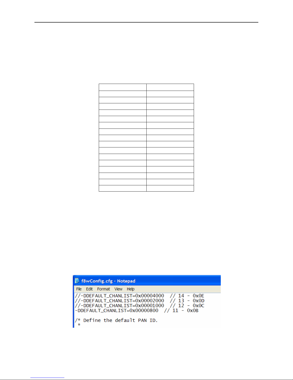
DEFAULT_CHANLIST is defined in the NLMEDE.h file. In addition, it can also be specified as
a compile option in a project’s configuration command file – this overrides the value in the
NLMEDE.h file. Configuration command files are found in the …\Projects\Tools\CC2430DB
folder. As shown below, a line in the f8wConfig.cfg file specifies the channel(s) that will be used
when the Z-Stack devices start up. This is the recommended location for developers to establish
specific channel settings for their projects. This feature allows developers set up a “personal”
channel to avoid conflict with others. Multiple channels can be specified by including the
appropriate bits in the DEFAULT_CHANLIST definition.
16 Copyright 2006-2007 Texas Instruments, Inc. All rights reserved.
Page 21

Z-Stack User's Guide - CC2431ZDK F8W-2006-0025 Version 1.4.3
7.1. Energy Level
The coordinator will start a network on a selected channel only if the energy level on that
channel is below a threshold value. The threshold value is set to -45dBm and can be modified by
changing the MAX_SCAN_ENERGY definition in the mac_scan.c file (available only with
TIMAC source file distribution). The value of this parameter minus 83 gives the maximum
tolerated energy level in dBm. To ensure that the coordinator will always find a suitable channel
to start the network on, it is recommended that more than one channel is selected.
Applicable Documents
Internal Documents
1. Serial Port Interface, F8W Document F8W-2003-0001
2. OSAL API, F8W Document F8W-2003-0002
3. Z-Stack API, F8W Document F8W-2006-0021
External Documents
4. Wireless Medium Access Control (MAC) and Physical Layer (PHY) Specifications for Low-
Rate Wireless Personal Area Networks (LR-WPANs), IEEE Standard 802.15.4, 05/12/2003.
17 Copyright 2006-2007 Texas Instruments, Inc. All rights reserved.
 Loading...