

Page 1
CBL 2™
Technical Reference
Calculator-Based Laboratory, CBL, and CBL 2 are trademarks of Texas Instruments Incorporated.
LabPro is a trademark of Vernier Software & Technology.
Santoprene is a registered trademark of Monsanto.
2000 Texas Instruments Incorporated. All rights are reserved.
Page 2

Contents
Introduction 5
Miscellaneous Reference Information 5
CBL 2 Software Upgrades 5
Data Collection Modes 5
Realtime Sampling 5
Non-Realtime Sampling 6
FastMode Sampling 6
Mode Comparison Table 7
Beep Sequences 8
Archiving in CBL 2’s
Memory 9
FLASH
Technical Specifications for Sensors 10
TI Light Sensor 10
TI Light Sensor Specifications 10
Stainless Steel Temperature Sensor 10
Stainless Steel Temperature Sensor Specifications 11
Temperature Accuracy 12
Stainless Steel Temperature Sensor Chemical Tolerance 12
TI Temperature Sensor Note 13
TI Voltage Sensor 13
Auto-ID Sensors 14
Custom Sensors 15
Connector Pinouts 16
Programming the CBL 2 17
Digital Output Buffer 17
Digital Output Buffer Example 17
Triggering and Thresholds 18
Measuring Period and Frequency 19
Example: Measuring Frequency 20
Asynchronous/ Synchronous Triggering versus Record Time 21
Example 21
CBL 2 Command Summary 22
Command 0 Reset CBL 2 RAM 23
Command 1 Channel Setup 23
Command 2 Data Type 26
Command 3 Trigger Setup 26
2 CBL 2 Technical Reference
Page 3

Command 4 Conversion Equation Setup (Analog) 28
Command 4 Sonic Temperature Compensation (Sonic) 30
Command 5 Data Control 30
Command 6 System Setup 31
Command 7 Request System Status 31
Command 8 Request Channel Status 33
Command 9 Request Channel Data 33
Command 10 Advanced Data Reduction 33
Command 12 Digital Data Capture 34
Command Sequence 34
General Information 36
Additional Notes on Command 12 41
Command 102 Power Control Command 41
Command 115 Check Set-up Information 41
Command 116 Check Long Sensor Name 42
Command 117 Check Short Sensor Name 43
Command 1998 Set LED Command 43
Command 1999 Sound Command 43
Command 2001 Direct Output to Digital-Out Port 43
Command 201 Archive Operations Command 44
Programming Examples 49
Example 1: Temperature Non-Realtime Data Collection 49
Example 2: Temperature Realtime Data Collection 49
Example 3: Distance and Velocity Non-Realtime
Data Collection 49
Example 4: Multiple Channels Non-Realtime Data Collection 50
Example 5: Conversion Equation Setup (Command 4) 50
Example 6: Data Control Setup (Command 5) 51
Example 7: Digital In Data Collection 51
Example 8: Digital Out 51
Example 9: CBL 2 LED Display 52
Example 10: Playing Music on the CBL 2 52
Example 11: Command 8 Program 52
Example 12: Command 9 Program 53
Example 13: Command 10 Program 53
Example 14: Archive Program (Command 201) 54
CBL 2 Technical Reference 3
Page 4

Appendix A: Glossary A-1
Appendix B: CBL 2 Error Messages B-1
Appendix C: DataMate Sensor Setup Default Settings C-1
4 CBL 2 Technical Reference
Page 5

Introduction
This technical reference is intended for CBL 2 users who want to write their own
programs for CBL 2 and Texas Instruments graphing calculators. This document includes
technical data such as specifications for sensors, syntax for CBL 2 commands, sample
programs, error codes, and miscellaneous other topics.
Instructions for using CBL 2 with the DataMate program or app are given in
Started with CBL 2
not addressed in this technical reference except for
Setup Default Settings
used by the DataMate program.
, which is included in the CBL 2 package. The DataMate program is
Appendix C: DataMate Sensor
. This table shows the default sensor settings and calibrations
Miscellaneous Reference Information
CBL 2 Software Upgrades
The CBL 2 uses
without buying a new CBL 2. As new functionality becomes available, you can
download the software from the TI web site to your PC and then use the TI-GRAPH
LINKé (sold separately) to upgrade your CBL 2.
Check the TI website (
compatibility statements. Directions for downloading upgrades will be given on the
web site.
FLASH
technology, which allows you to easily upgrade to new software
www.ti.com/calc
) for upgrades, paying special attention to
Getting
Data Collection Modes
On the CBL 2, data can be collected in one of three modes: realtime, non-realtime or
FastMode.
♦
In
realtime
after each point is taken.
♦
In
non-realtime
all of the data points are taken and then sends it to the calculator.
♦
In
FastMode
very fast sample rate, stores it internally until all of the data points are taken, and
then sends it to the calculator.
It is the default to return the time with the data collected.
CBL 2 Technical Reference 5
data collection, the CBL 2 collects data and sends it to the calculator
data collection, the CBL 2 collects data and stores it internally until
data collection, the CBL 2 collects data on a single analog channel at a
Page 6

Realtime Sampling
In realtime data collection, the CBL 2 sends each data point to the calculator as it is
taken, so some data can be lost if the calculator is not ready to accept the data. In
addition, the quantity of data that can be collected is limited by the size of the
calculator memory.
Realtime data collection is used for:
♦
Slower sampling where the user wants to see the data as it is being collected.
♦
Very long data collection times where the CBL 2 may run out of memory during
data collection.
♦
Situations where the host calculator must process the data as soon as it becomes
available (such as to control an output in response to a temperature input).
This data collection mode should not be used for data collection of more than a few
points each second because the host calculator will not be able to keep up. In addition,
because of the nature of realtime data collection, the period/frequency and Command
12 channels cannot be sampled in this mode.
Since the number of points to be collected may not be known at the start of sampling,
set the “number of samples” to M1 when sending Command 3. This tells the CBL 2 to
take data but not send it to the host calculator until the calculator requests data.
Non-Realtime Sampling
In non-realtime data collection, the samples are taken and stored in the CBL 2 memory
until all the data has been collected. Then the data is sent to the host calculator. The
quantity of data collected is not limited by the size of the calculator memory, but is
limited by the size of the CBL 2 memory. Up to 12,000 samples max (or less under some
conditions) can be collected in non-realtime.
Non-realtime data collection is used for fast sampling of multiple channels and when
triggering is required.
All of the channels can be used in this mode, and the Command 12 functions can be
used. The sample time is limited by the number and types of channels enabled. For a
E
single channel, the sampling can be as fast as 1
calculator communication is maintained during the sampling. This allows the host
calculator to issue a Command 7 or Command 8 to ascertain the progress of the
sampling without disturbing the sampling process.
-4 second. In addition, normal
FastMode Sampling
FastMode sampling is designed to be used where a single channel must be sampled at
very fast sample times. This mode is used primarily when sampling sound using the
microphone.
6 CBL 2 Technical Reference
Page 7

In general, FastMode is identical to non-realtime sampling with the following
exceptions:
♦
The sampling is limited to a single analog channel when doing FastMode sampling.
♦
The selected channel must not be in operation mode 5, 6, or 7.
♦
The communications with the host calculator are turned off during FastMode
sampling.
Note: In FastMode sampling, it is very important that the program not issue a GET command
until after sampling has been completed. If the CBL 2 receives a GET command it will abort
FastMode sampling with an error in order to respond to the GET command.
In FastMode, the sample times can be as fast as 20 msec (a sample frequency of 50KHz).
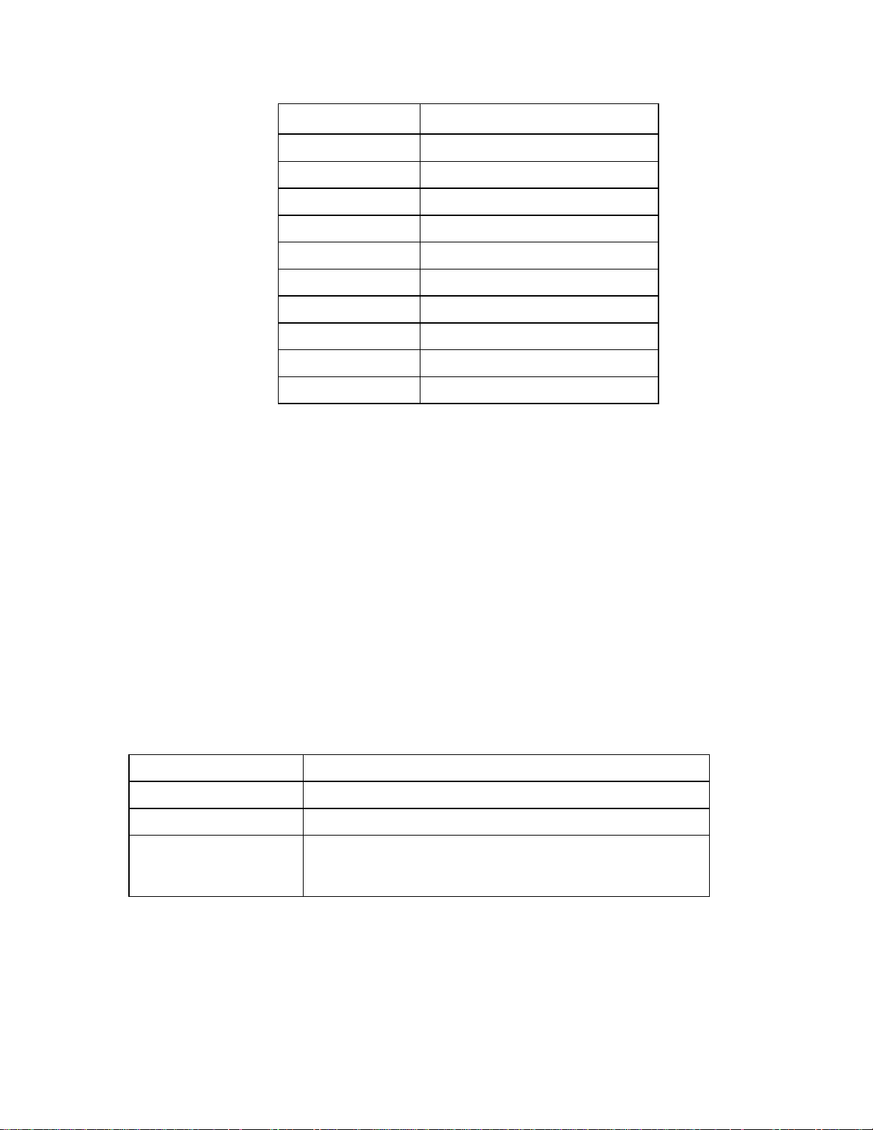
Mode Comparison Table
The table below shows some of the differences between the data collection modes.
Order of data
returned when
doing the GETs
from the host
calculator
Number of samples
limited?
Sample time limits
(approximate)
Number of
channels limited?
Realtime Mode
{ch1_1, ch2_1, …
deltatime_1}
{ch1_2, ch2_2, …
deltatime_2}
:
:
{ch1_n, ch2_n, …
deltatime_n}
Not by CBL 2, but
may be limited by
the host calculator
Sample Time > .25
second to 16000
seconds
Yes, only CH1-3
and 11
Non-Realtime
Mode
{ch1_1, ch1_2, …
ch1_n}
{ch2_1, ch2_2, …
ch2_n}
{ch3_1, ch3_2, …
ch3_n}
{time_1, time_2, …
time_n}
Yes, limited by
available memory
in CBL2
Sample Time ‚ 1e-4
seconds to 16000
seconds
No Yes, only a single
FastMode
Same as NonRealtime
Same as NonRealtime
Sample Time ‚ 2e-5
seconds to 1e-4
seconds
channel from CH1
to CH3
Can use
Triggering?
Communication
maintained during
sampling?
CBL 2 Technical Reference 7
No Yes Yes
Yes Yes No
Page 8

Beep Sequences
The CBL 2 makes four kinds of sounds:
♦
A low tone followed by a high tone (low-to-high beep).
♦
A medium tone followed by another medium tone (medium-medium beep).
♦
A high tone followed by another high tone (high-high beep).
♦
A “tick” sound when a key is pressed.
The following bullets explain when beep sequences normally occur and what the beep
sequences mean.
♦
When the CBL 2 completes initialization, you will hear the startup sequence: highhigh beep, medium-medium beep, low-to-high beep (6 total beeps, plus LEDs light
up in this order: red LED, yellow LED, and green LED)
♦
When you press the QUICK SETUP button:
the medium-medium beep sounds if a sensor is attached to the CBL 2.
−
the high-high beep sounds if no sensors are attached to the CBL 2.
−
♦
When the CBL 2 is connected to a calculator during sampling commands:
the medium-medium beep sounds when initializing data collection.
−
the medium-medium beep sounds when starting data collection (transition from
−
pre-store to store).
the medium-medium beep sounds when completing data collection.
−
Note: If the sampling timing causes the beeps to run together, the CBL 2 software may not
sound all the beeps.
Note 2: You will not get all the beeps when Fast Sampling is enabled.
Note 3: You will not get all the beeps when using triggering.
♦
When you set the CBL 2 for manual trigger and press the START button, a mediummedium beep sounds.
♦
When you press the TRANSFER BUTTON:
the low-to-high beep sounds when the transfer succeeds.
−
the high-high beep sounds if the transfer fails for any reason.
−
♦
When an overcurrent condition is detected, five high-high beeps sound. (This causes
an error, which causes even more beeps to sound.)
♦
When the CBL 2 begins a full self-test, three low-to-high beeps sound.
♦
When self-test completes:
the low-to-high beep sounds if self-test passes.
−
the high-high beep sounds if self-test fails.
−
8 CBL 2 Technical Reference
Page 9

When the CBL 2’s base code detects an error in the commands sent from the host, a
♦
high-high beep sounds twice.
When the CBL 2 powers up:
♦
two high-high beeps sound if the base code is not loaded.
−
three high-high beeps sound if the power-up self-test fails.
−
During base code download, three high-high beeps sound when any errors occur.
♦
(The unit resets and then the two high-high beeps mentioned in the previous bullet
sound.)
Archiving in CBL 2’s
The
FLASH
allowing updates to the operating system and storing the DataMate programs, the
FLASH
To preserve collected data so that it can be retrieved at a later time, data sets can be
stored in the
data set can be given a name.
You can write a program on the calculator to review the list of stored data sets and
♦
retrieve the desired one for further analysis. (See the sample archive program on
page 56.)
You can use the DATADIR program (available on the TI Resource CD or on the TI
♦
web site at
DATADIR program are given in
The
FLASH
convenient location for storing frequently used programs or as a temporary storage to
create more available memory on the calculator.
Command 201, in conjunction with the Link menu on the calculator, provides access to
these
memory in the CBL 2 can be used for several purposes. In addition to
memory serves as an archive space for other programs and data.
FLASH
archive can also store calculator programs and applications. This provides a
FLASH
archive operations. For details about Command 201, see page 44.
archive. To distinguish between different stored data sets, each
www.ti.com/calc
FLASH
) to manage
Memory
FLASH
Getting Started with CBL 2
memory. Directions for using the
.
CBL 2 Technical Reference 9
Page 10

Technical Specifications for Sensors
TI Light Sensor
The TI light sensor uses a phototransistor to measure relative irradiance. The units of
irradiance are milliwatts per square centimeter. The light sensor’s output is a voltage
that is linearly proportional to the amount of irradiance it senses. The range of light
2
over which the sensor is sensitive is 10µW/cm
to 1mW/cm2.
The
auto-ID
measured voltage to relative units. The sensor is direction dependent and achieves the
highest output when the end of the sensor is pointed directly at the light source.
The light sensor is sensitive in the visible and near-infrared (
you can use it with
is designed to work in air only—it is not waterproof.
The light sensor returns
vary from light sensor to light sensor. The light sensor readings are also sensitive to
temperature.
resistor in the sensor causes the CBL 2 software to automatically convert the
) light range. This means
IR
emitting diodes as well as all visible light sources. The light sensor
IR
relative
readings, not absolute irradiance readings. Values may
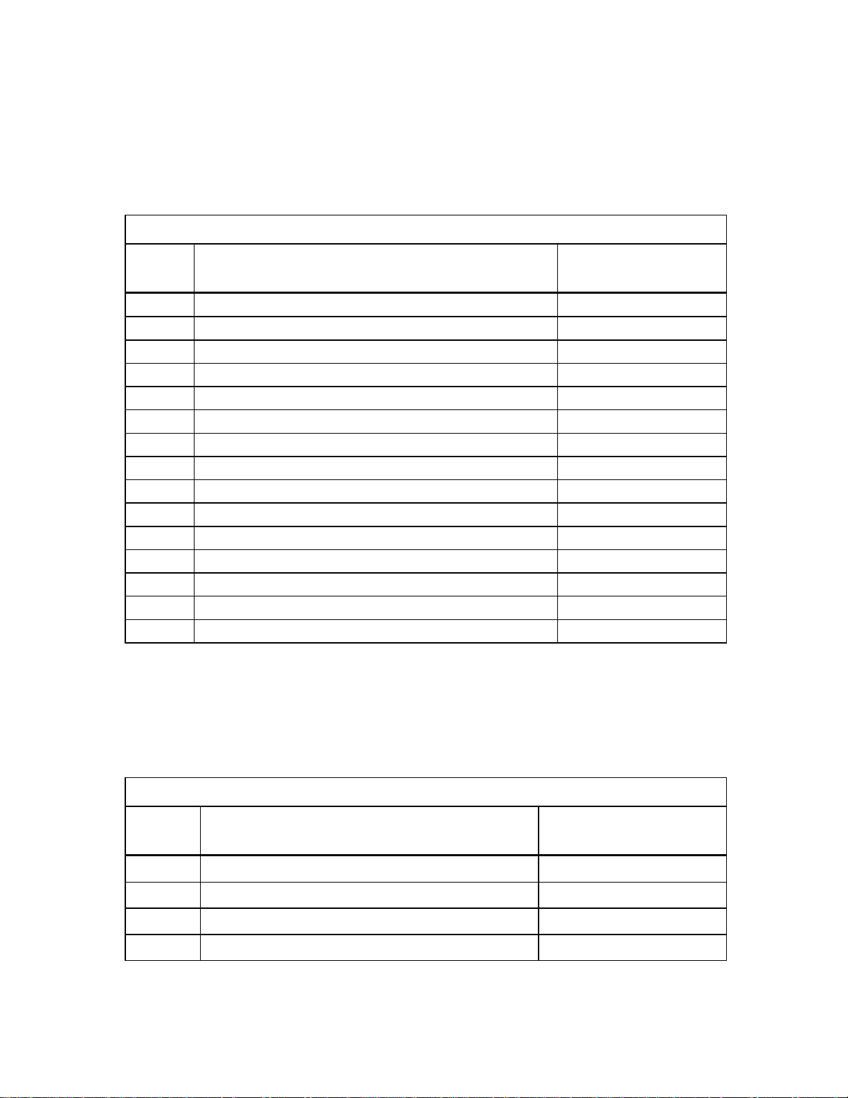
TI Light Sensor Specifications
Channels Connects to
channels)
Current drain 5 mA max.
Voltage range 0–5 Volts
Irradiance range 10µW/cm2 to 1mW/cm2 (approximately)
Spectral response range 300nm to 1100nm (nanometers) (non-flat
response)
CH1, CH2, CH3
(analog
Chemical tolerance None (air only)
Pins used 2 ground
4 auto-ID resistor
5 +5 Volts DC
6 Signal
Stainless Steel Temperature Sensor
The Stainless Steel Temperature Sensor is an auto-ID general-purpose laboratory
temperature sensor that comes with your CBL 2. The sensor is rugged and durable, and
is designed to be used as you would use a thermometer for experiments in chemistry,
physics, biology, earth science, and environmental science.
10 CBL 2 Technical Reference
Page 11

This probe uses the 20 kΩ NTC Thermistor. The thermistor is a variable resistor whose
resistance decreases nonlinearly with increasing temperature. The best-fit
approximation to this nonlinear characteristic is the Steinhart-Hart equation. The CBL 2
or CBL interface measures the resistance value, R, at a particular temperature, and
converts the resistance using the Steinhart-Hart equation:
T = [K
where T is temperature (°C), R is the measured resistance in kΩ, K
-
= 2.22468 X 10
K
1
4
, and K2 = 1.33342 X 10⁻⁷. Fortunately, CBL 2 and CBL take care of this
+ K1(ln 1000R) + K2(ln 1000R)3]-1 – 273.15
0
= 1.02119 X 10
0
conversion for you, and provide readings in °C (or other units, if you load a different
calibration).
Stainless Steel Temperature Sensor Specifications
Channels Connects to CH1, CH2, CH3 (analog channels)
Current drain 0.5 mA max.
Temperature range -25 to 125°C (-13 to 257°F)
Maximum temperature
sensor can tolerate
without damage
10-bit resolution 0.32°C (-25 to 0°C)
Temperature sensor 20 kΩ NTC Thermistor
150°C
0.12°C (0 to 40°C)
0.4°C (40 to 100°C)
1.0°C (100 to 125°C)
-
3
,
Accuracy ±0.2°C at 0°C, ±0.5°C at 100°C
Response time 95% of full reading: 11 seconds
98% of full reading: 18 seconds
100% of full reading: 30 seconds
Probe dimensions Probe length (handle plus body): 16 cm
Stainless steel body: length 11 cm,
diameter 4.0 mm
Probe handle: length 5.0 cm, diameter 1.25 cm
Pins used 2 Ground
3 Vres
4 auto-ID resistor
6 Signal
CBL 2 Technical Reference 11
Page 12

Temperature Accuracy
This probe provides very accurate temperature readings. Near 0°C, readings are
accurate to ±0.2°C; near 100°C, readings are accurate to 0.5°C.
Important:
you cannot re-calibrate this sensor. Probe-specific calibrations should not be necessary
when using this sensor.
Because of the non-linear nature of the Stainless Steel Temperature Probe,
Stainless Steel Temperature Sensor Chemical Tolerance
The body of this sensor is constructed from grade 316 stainless steel (0.08% carbon,
2.0% manganese, 0.75% silicon, 0.04% phosphorus, 0.03% sulfur, 16-18% chromium,
10-14% nickel, 2-3% molybdenum, and 0.1% nitrogen). This high-grade stainless steel
provides a high level of corrosion resistance for use in the science classroom.
Here are some general guidelines for using this probe:
1.
The probe handle is constructed of molded plasticized Santoprene®. While this
material is very chemical resistant, we recommend that you avoid submerging the
probe beyond the stainless steel portion.
2.
Always wash the probe thoroughly after use.
3.
The probe can be left continuously in water at temperatures within the range of
–25° to 125°C. Continuous usage in saltwater will cause only minor discoloration of
the probe, with no negative effect on performance.
4.
You can leave the probe continuously in most organic compounds, such as
methanol, ethanol, 1-propanol, 2-propanol, 1-butanol, n-hexane, lauric acid,
paradichlorobenzene, phenyl salicylate, and benzoic acid. The probe should not be
left in n-pentane for more than 1 hour.
5.
The probe can be left in strong basic solutions, such as NaOH, for up to 48 hours
with only minor discoloration. We do not recommend usage in basic solutions that
are greater than 3 M in concentration.
6.
The following chart provides the maximum length of time we recommend for
probe exposure to some common acids. Probes left in an acid longer than these
times may bubble and/or discolor, but will still be functional. We do not
recommend probes be left in
Acid
1 M HCI 20 minutes
2 M HCI 10 minutes
3 M HCI 5 minutes
1 M H2SO
2 M H2SO
12 CBL 2 Technical Reference
4
4
acid longer than 48 hours.
any
Maximum Exposure Time
48 hours
20 minutes
Page 13
Acid
3 M H2SO
1 M HNO
2 M HNO
3 M HNO
1 M CH3CO OH 48 hours
2 M CH3CO OH 48 hours
3 M CH3CO OH 48 hours
1 M H3PO
2 M H3PO
3 M H3PO
7.
Cole Parmer has an extensive listing of chemical compatibility of grade 316 stainless
steel on their web site (
be used for general guidelines not covered in this summary.
4
3
3
3
4
4
4
www.coleparmer.com/techinfo
TI Temperature Sensor Note
Maximum Exposure Time
10 minutes
48 hours
48 hours
48 hours
48 hours
48 hours
48 hours
). This listing can
If a TI Temperature sensor (the flexible temperature sensor that came with the original
CBL) is used with CBL 2, it will auto-ID as the Stainless Steel Temperature sensor. Both
sensors use the same calibration that is built into the CBL 2.
TI Voltage Sensor
The TI voltage sensor is a generic sensor that you can use to read any voltage between
±10 Volts. The auto-ID resistor contained in the sensor causes the CBL 2 software to
automatically measure voltage. No conversion equation is loaded. The black hook
should be connected to ground and the red hook to the signal voltage.
Channels Connects to CH1, CH2, CH3 (analog channels)
Voltage range ±10 Volts
Chemical tolerance None (air only)
Pins used 1 Signal
2 Ground
4 auto-ID resistor
Note: It is very important that the ground connections of the analog inputs are never connected
to different potentials. These ground connections are all in common. Connecting the grounds to
different potentials may damage the CBL 2.
CBL 2 Technical Reference 13
Page 14
1
1
Auto-ID Sensors
The CBL 2 contains provisions for the auto-ID sensor resistor values listed below. If
needed, a conversion equation is loaded automatically for some of the auto-ID values.
Channels 1, 2, and 3
IDENT
Valu e
2.2KThermocouple °CM200C to 1400¡C
33KTI Voltage sensorM10 to +10 Volts
6.8K Current sensor
3.3K Resistance sensor 1K to 100K
22K Extra long temperature sensor for °C
68K CO2 gas sensor (PPM) 0 to 5000 ppm
100K Oxygen gas sensor (PCT) 0 to 27%
150K C V voltage sensor (V)
220K C V current sensor (A)
10K Stainless steel or TI temperature sensor3 for °C
15K Stainless steel or TI temperature sensor for °F
4.7K TI Light sensor 0 to 1
1K Ex heart rate sensor (BPM) N/A
47K Voltage sensor 0 to 5 Volts
1.5K EKG N/A
Sensor Type
Range
2
M
10 to +10 Amps
J
L
50°C to 150°C
M
6 to +6 Volts
M
0.6 to +0.6 Amps
M25¡
C to 125¡C
M13¡
F to 257¡F
1
IDENT values are resistance values in ohms (tolerance ±5%).
2
Operation 3 is a mathematical conversion of voltage to a current reading (1V=1A).
There is no circuitry inside the CBL 2 unit to convert current to voltage; this must be
done in the external probe.
3
Default units for the Stainless Steel and TI Temperature sensors is °C.
Channel 11 (SONIC)
IDENT
Valu e
15K Motion detector, meters ½ meter to 6 meters
22K Motion detector, meters ½ meter to 6 meters
10K Motion detector, feet 1½ feet to 18 feet
33K Photogate sensor N/A
1
IDENT values are resistance values in ohms (tolerance ±5%).
14 CBL 2 Technical Reference
Sensor Type
Range
Page 15

Custom Sensors
To create custom-designed sensors or other circuits for the analog input channels, the
sonic input channel, the digital input channel, or the digital output channel on the
CBL 2, you can purchase sensor kits from TI (
♦
For a custom analog sensor, use the Analog Probe Kit (order entry no. CBL/CA/D).
1-800-TI-CARES
Each sensor kit includes a four-foot length of telephone cable with a connector
attached to one end. The other end of the cable is not terminated.
♦
For a custom digital sensor, cut a CBR-to-CBL cable (order entry no. CBR/CA/C) into
two pieces to get two lengths of cable with connectors. (The digital probe kit used
with the original CBL will not work with CBL 2.)
♦
For a custom digital ID probe, contact Vernier Software and Technology
(
www.vernier.com
) for more information.
Be very careful when designing a custom sensor or circuit. For more accurate operation,
do not connect pins 1 and 6 together on the analog input channels. Pin 1 on the British
Telecom-style connector is the pin farthest from the release lever as shown in the
pictures below.
If you design a resistance-type sensor, connect pin 3 (Vres) to pin 6 (Vin-low) (refer to
“Connector Pinouts” below). Connect the resistance to be measured from the junction
of these pins to pin 2 (Gnd). The resistance range for useful measurements is limited
from approximately 1 Kohms to 100 Kohms.
) or its Instructional Dealers.
When the Operation parameter in Command 1 (page 23) is set to 2, 3, 5, 6, or 7, the
data is measured on the Vin pin (pin 1). The data for all other operations is measured
on the Vin-low pin (pin 6).
Note: The most current that can be drained from all three analog channels is 160 mA. This is
limited by the hardware.
CBL 2 Technical Reference 15
Page 16
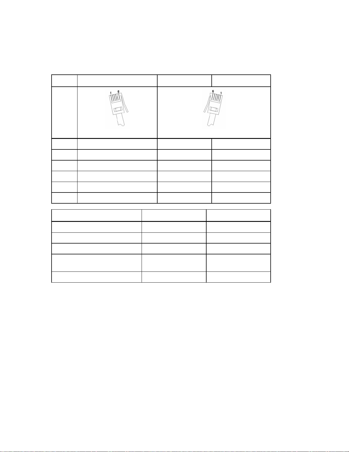
Connector Pinouts
The CBL 2 sensors use 6-pin British Telecom-style connectors.
Pin
1 Vin Echo DI0
2 Gnd Init DI1
3 Vres/Smart ID CLK Auto-ID DI2
4 Auto-ID +5 Volts DC +5 Volts DC
5 +5 Volts DC Gnd Gnd
6 Vin-low Not Applicable DI3
Channels: CH1, CH 2, CH 3 CH1, CH2, CH3
Input signal: Analog data Analog data
Analog CH1, CH2, CH3
(Right-hand Connector) (Left-hand Connector)
SONIC
Vin
DIG IN/OUT
Vin-low
Input range: ±10 Volts 0 to 5 Volts
Resolution (using CBL 2’s
10-bit A/D converter):
Input impedance: 1.046 M
Vres:
♦
♦
♦
♦
♦
♦
♦
Output reference voltage from the CBL 2 through a 15 Kohm resistor. When
using this feature, Vres should be tied to Vin-low and the value to be measured
should be connected between Vin-low and Gnd.
Gnd:
Ground (common for all channels).
Auto-ID: Auto-ID
pin 4 to ground.)
Echo:
Init:
Ultrasonic motion detector input.
Distance initialization signal
sensor detection data input. (
D0 In/Out to D3 In/Out:
Smart ID Clk:
Clock to synchronize data transfer from smart probes.
19.6 mV 5.6 mV
J
>10 M
Auto-ID
Input or output pins for digital pulses.
J
resistor connected from
16 CBL 2 Technical Reference
Page 17

Programming the CBL 2
Digital Output Buffer
The digital output buffer (DOB) is a circular buffer that contains up to 32 elements. The
output from the buffer is 4-bits wide, and the outputs are CMOS (0-5V) compatible.
The data in Command 1 is entered as decimal representation of the digital value that is
output. For example, 0=0000, 5=0101, and 15=1111. At the beginning of each sample, a
pointer into the digital output buffer is incremented and the next available data is sent
to the output lines.
The electrical characteristics of the digital outputs are:
♦
Voutput-high ‚ 3.7V @ M400uA
♦
Voutput-low 0.65V @ 1.6mA
The number of times that the DOB outputs the contents of the buffer depends on the
number of data elements defined in Command 1 and the number of samples defined
in Command 3.
Digital Output Buffer Example
Command 1 list is {1,31,5,1,2,3,4,5}
where:
1=Channel Setup.
31=DIG OUT.
5=Five data elements.
1=0001 (digital nibble).
2=0010 (digital nibble).
3=0011 (digital nibble).
4=0100 (digital nibble).
5=0101 (digital nibble).
Command 3 list is {3,1,100}
where:
3=Sample and Trigger Setup.
1=One second sample time.
100=One hundred samples.
(Trigger Type defaults to manual
triggering.)
CBL 2 Technical Reference 17
Page 18
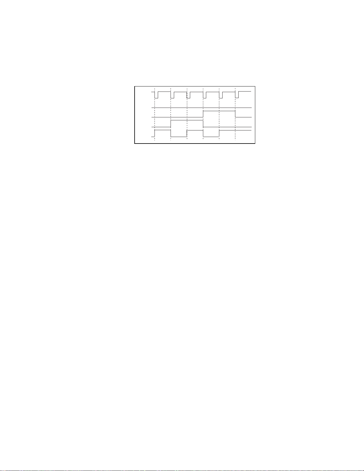
The DOB outputs pulses that correspond to the five digital nibbles (1234512345...12345
etc.). This sequence is repeated 20 times (100 samples/5 data elements) to the DIG OUT
channel. The diagram below shows a portion of this output for the first five data
elements.
Sample
Clock
D3
D2
D1
D0
1234
1
5
Figure 1. Digital Output Example
Triggering and Thresholds
Two types of triggering thresholds can be set in the CBL 2:
♦
Hardware triggering
is set to trigger on a specific voltage level established by the
trigger threshold parameter.
♦
Software triggering
is set to begin data collection on either the rising edge or
falling edge of the signal, depending on the trigger type and trigger threshold
selected.
The THRESHOLD parameter specified in Command 3 can be used for two purposes:
♦
If the operation in Command 1 is frequency, period, or count (operation = 5, 6, or 7
on Channel 1 only), then the threshold parameter in Command 3 sets a voltage
level in the CBL 2 hardware. The signal on the Vin pin of CH 1 must pass through
this voltage for the CBL 2 to see the signal change states.
♦
If the operation in Command 1 is anything other than 5, 6, or 7, then the threshold
parameter in Command 3 specifies a trigger level and is measured in the units of
the sensor selected.
When triggering, sampling does not start until the signal on the trigger channel (also
specified in Command 3) passes through this level once in the direction specified. This
comparison of trigger level and signal level occurs in software, so any level in the
proper range can be selected. Also, either the Vin or VinLow pin (on any of the analog
channels or the sonic channel) can be used as the trigger channel. CBL 2 knows
whether to use the Vin or VinLow pin by looking at which operation was set up in
Command 1.
18 CBL 2 Technical Reference
Page 19
0
1
2
3
T=
+
-
+
-
If a conversion equation is enabled for the trigger channel, then the threshold
specified in Command 3 should be a converted level. For example, if a pH probe is
plugged into CH 2 with a conversion equation loaded into CBL 2 and the trigger
channel specified as CH 2, the threshold level should be entered as a pH level in the
range 0-14, not as a voltage in the range 0-5V.
Measuring Period and Frequency
Period and frequency apply only to CH1 and only CH1 can be active if the operation is
set to 5 (Period) or 6 (Frequency). Period and frequency are measured on Vin pin (pin 1)
of CH1. Period and frequency measurements always use the hardware threshold.
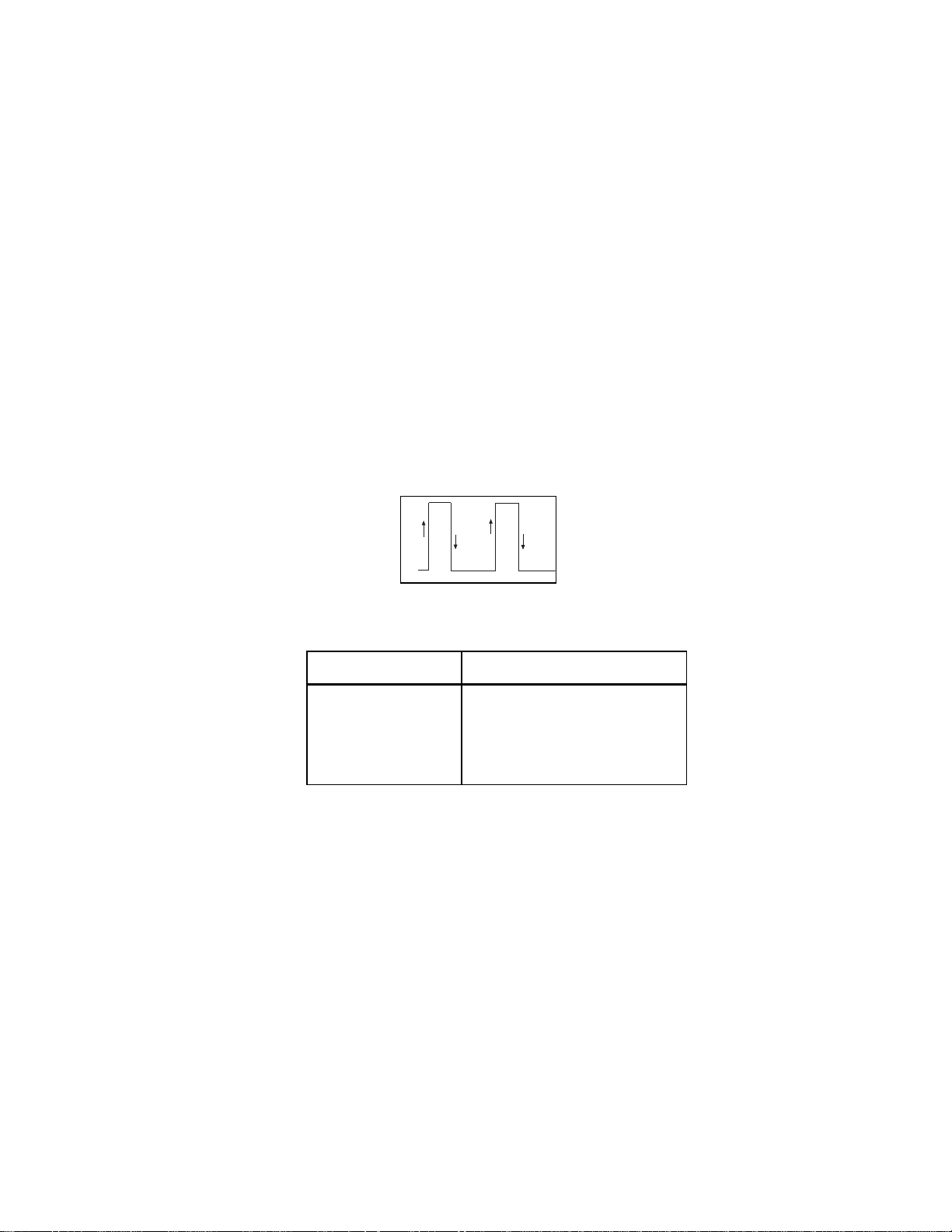
The CBL 2 measures period and frequency by counting edges for 0.25 seconds, or by
measuring the time between the selected edges for one period—whichever is larger
(see figure below). If a significant number of edges are counted during the 0.25-second
period, the count is used to compute both period and frequency; otherwise, the period
and frequency are computed from the time interval for one period.
Figure 2. Period and Frequency Measurement
Trigger Type
2
3
4
5
Measuring Points
+ + (T=0 to 2)
N N
N + N
N N
(T=1 to 3)
(T=0 to 1)
+ (T=1 to 2)
The crossover point between the two computations is about 600 Hz. Because there can
be a one-count uncertainty during the 0.25-second period, the accuracy around 600 Hz
is approximately ±4 Hz (about 0.7%). The resolution of the timer measuring the time
between edges is 6.4 microseconds; therefore, the percentage accuracy improves for
frequencies above and below 600 Hz.
If the CBL 2 is set up using Command 3 to make multiple measurements at a particular
sample time, the CBL 2 waits for the sample time that you specified after it completes
the current measurement. It then initiates the next cycle of period/frequency
measurement. The minimum sampling time for period and frequency is 0.25 seconds.
Note: Period and frequency measurements using Trigger Type 4 or 5 are only possible on nonrepetitive signals or on repetitive signals that are less then 600 Hz. This is because at 600 Hz, the
edge counts will prevail.
CBL 2 Technical Reference 19
Page 20

The parameters shown in this table are used when measuring period or frequency.
Trigger Type
0 Rising (+) Trigger Threshold parameter
2–5 Specified by trigger type Trigger Threshold parameter
6 Not allowed (E.34 error).
Edge Polarity Used
Hardware Threshold Used
Example: Measuring Frequency
Assume a frequency measurement is requested on CH 1, and 20 measurements are
desired at a .5 second sample time. The following commands would set up the CBL 2
for this example:
{1,1,6}
{3,.5,20,2,0,1}
3 = Sample and Trigger setup command
.5 = Sample time of 0.5 seconds
20 = Number of samples to take
2 = Trigger from rising edge to rising edge for frequency
0 = Trigger channel not applicable
1 = Trigger at 1 Volt
Assume a ±10 Volt, 20 Hz sine wave is the input signal on pin 1. The CBL 2 follows the
sequence of steps indicated below when the first trigger occurs (a trigger occurs every
0.05 seconds).
1. Trigger occurs on the rising edge.
2. Start counter and timer.
3. Stop timer at next rising edge.
4. Wait until 0.25 seconds has elapsed.
5. Stop counter (count should be about 5).
6. Count is less than 150 (or 600 Hz); therefore, frequency is computed from the
time interval for one period.
7. Wait for 0.5 seconds specified in Sample Time.
8. Wait for additional processing time to complete. (This time depends on what
processing is currently being performed and is typically about 0.25 additional
seconds.)
9. Repeat steps 1 through 8 for nineteen more samples.
In this example, the CBL 2 takes approximately 15 seconds to complete all the sampling
and turn on the DONE indicator in the display.
20 CBL 2 Technical Reference
Page 21

Asynchronous/ Synchronous Triggering versus Record Time
Actual triggering is asynchronous from the internal sampling clock when Trigger Type
in Command 3 is set to 1 or 6 (manual triggering). If sampling at very fast rates, the
actual trigger may be slightly different from the commanded trigger. The user should
take this into account when calculating prestore and trigger levels.
The actual sample time for the trigger point depends on whether or not prestore is
selected in Command 3.
When prestore and relative record time are selected, the sample time for the trigger
point will generally not be identical to times around it. The time recorded for the
trigger point will be the actual time between the previous sampled point on the
internal sampling clock interval and the asynchronous trigger event. The sample taken
after the trigger point will be at the specified sample time since the clock is reset each
time the trigger event occurs (pressing START/STOP or the hardware threshold trigger
event).
When Trigger Type is set to 6 (Manual and Sample Trigger) in Command 3, the
recorded sample times are the actual relative times when START/STOP is pressed.
When no prestore is selected, the first sample time will be the trigger point. Its
recorded time will not be the internal sample clock time because the CBL 2 is always
sampling on the internal clock interval that you selected and is storing points (if you
selected prestore) until the trigger event occurs.
Example
Assume the following:
♦
Input to CH1, set to measure ±10 Volts, is a 0.01 Hz sine wave.
♦
Sample Time is set to 10 seconds and Number of Samples is set to collect 30 points.
♦
Trigger Channel is set to 1.
♦
Trigger Threshold is set to 1.0 and Trigger Type is set to 2 (trigger on rising edge).
The CBL 2 will collect and store a sample every 10 seconds. The recorded time for each
sample will be 10 seconds. The trigger event (signal rising through 1.0 Volts) occurs 1.5
seconds after the previous sample, so a sample collected at the trigger point is taken
and stored with a recorded time of 1.5. The next sample is taken 10 seconds after the
trigger sample, not 8.5 seconds later as would have happened if the internal sample
clock had not been reset.
The Record Time returned (around the trigger point) will be the list:
{...10,10,10,1.5,10,10,...}.
CBL 2 Technical Reference 21
Page 22

CBL 2 Command Summary
The table below lists the commands you can use in writing programs for CBL 2.
Detailed explanations of each command and its syntax can be found beginning on the
page number shown in the third column.
Command
Number
0 Reset:
1 Channel Setup:
2 Data Type:
sent. It is included only for compatibility with older CBL
programs.
3 Trigger Setup:
experiment.
4 Conversion Equation Setup (Analog Channels):
parameters to convert physical units measured by CBL 2 into
a more useful measurement unit such as Newtons or ¡C.
Sonic Temperature Compensation (Sonic Channel):
Sets the unit of measurement for sonic data.
5 Data Control:
well as the starting and ending data points to be retrieved
by a TI calculator.
6 System Setup:
for the CBL 2; selects a filter to be applied to data.
Resets all channels to default conditions. 23
This command is not used and should not be
Command Description
sets up a channel for data collection. 23
Sets up the trigger parameters for an
Selects the type of data to be retrieved, as
Turns sound on or off; sets an ID number
Sets up
See
Page
26
26
28
30
30
30
7 Request System Status:
status information.
8 Request Channel Status:
return sensor type, last valid data, and last valid data
position for the requested channel.
9 Request Channel Data:
one data point before sampling starts. Used to verify that
setup is correct.
10 Advanced Data Reduction:
certain time-intensive algorithms instead of processing them
in the calculator.
12 Digital Data Capture:
of motion data from the digital input channel.
102 Power Control Command:
power-saving; or designated power up.
22 CBL 2 Technical Reference
Generates and prepares to return
Generates and prepares to
Generates and prepares to return
Sets up CBL 2 to process
Sets up the capture or measurement
Sets the power to always on;
31
32
33
33
34
41
Page 23

Command
Number
115 Check Set-up Information:
the designated channel.
116 Check Long Sensor Name:
117 Check Short Sensor Name:
1998 Set LED Command:
1999 Sound Command:
sounds.
2001 Direct Output to Digital-Out Port:
digital output port during a sampling run.
201 Archive Operations Command:
determine the contents of the CBL 2’s
Detailed information about each command is given below. The table following each
syntax lists valid values. Default values appear in
Command Description
Returns status information for
Returns long sensor name. 42
Returns short sensor name. 43
Turns LEDs on and off on command. 43
Specifies length and frequency of CBL 2
Outputs data to the
Allows the calculator to
FLASH
boldface
memory.
type.
Command 0 Reset CBL 2 RAM
See
Page
41
43
43
44
Syntax:
This command has no parameters or options. Clears data memory back to power-up
state. Clears error information. Resets only the RAM; does not clear
This command should be sent at the beginning of each program.
{0}
FLASH
memory.
Command 1 Channel Setup
This command sets up a channel for data collection. It has six syntaxes, as shown below.
Syntax:
Clears all channels.
Syntax: {1,channel,
Turns off the selected channel.
Channel
1-3 = Analog
11 = Sonic
21 = Digital Input
{1,0}
0}
31 = Digital Output
CBL 2 Technical Reference 23
Page 24

Syntax:
{1,
channel,operation,post-processing,(delta) 1,equ
Use this syntax to set up analog channels.
Operation/
Channel
1-3 = Analog
Sensor Type
0 = Turn channel off
1 = Auto-ID this sensor
(default is 0-5V sensor)
2 = TI Voltage „10V
3 = Current „10A
4 = Resistance
4
= Measure period on
5
„
10V input line (CH 1
only)
4
= Frequency on „10V
6
input line (CH 1 only)
5
= Count transitions
7
on „10V input line
(CH 1 only)
Post-Processing
0 = None (RT
and NON-RT3)
1 = d/dt (NON-RT)
2 = d/dt and d
(NON-RT)
2
2
/dt
}
Conversion Equation
0 = Off
1 = On (must also
send Command 4)
2
10 = TI Temperature or
Stainless Steel
Temperature
(Centigrade)
11 = TI Temperature or
Stainless Steel
Temperature
(Fahrenheit)
12 = TI Light
14 = Low voltage (0-5V)
1
This parameter is ignored.
2
RT: REALTIME mode sampling.
3
NON-RT: NON-REALTIME mode sampling.
4
When using Command 1 operation 5 or 6, Trigger Type in Command 3 must be 2, 3, 4
or 5.
5
When using Command 1 operation 7, Trigger Type in Command 3 must be 0.
24 CBL 2 Technical Reference
Page 25

Syntax:
Use this syntax to set up the sonic channel.
{1,11,
operation,post-processing,(delta)1,equ
Operation
0 = Resets channel
1 = Meters – Returns distance and
@
time (RT and NON-RT)
2 = Meters – Returns distance and
@
time (RT and NON-RT)
3 = Feet – Returns distance and @time
(RT and NON-RT)
4 = Meters – Returns distance, velocity,
and @time (RT) or distance and @time
(NON-RT)
5 = Feet – Returns distance, velocity,
and @time (RT) or distance and @time
(NON-RT)
6 = Meters – Returns distance, velocity,
acceleration, @time (RT) or distance
and @time (NON-RT)
Post-Processing
0 = None (RT
and NON-RT3)
1 = d/dt (NON-RT)
2 = d/dt and d
(NON-RT)
2
2
/dt
}
Conversion Equation
0 = Off
1 = On (must also send
Command 4 for
temperature
2
compensation)
7 = Feet – Returns distance, velocity,
acceleration, @time (RT) or distance
and @time (NON-RT)
1
This parameter is ignored.
2
RT: REALTIME mode sampling.
3
NON-RT: NON-REALTIME mode sampling.
Note: When post-processing is enabled in non-realtime sampling mode, all operations will
return the first derivative and the second derivative.
Syntax:
Use this syntax to set up the digital input channel.
Channel
21 = Digital Input
{1,
channel,operation
Operation
0 = Off
1 = On
}
CBL 2 Technical Reference 25
Page 26

Syntax:
Use this syntax to set up the digital output channel.
Channel
31 = Digital
Output
The CBL 2 outputs one element for each sample. Between samples, the output returns
to 0 unless the user has commanded the power to remain on (using Command 102, M1).
Caution: Using Command 102, M1 can drain the CBL 2 batteries.
{1,
channel,operation,list of values
Operation
0 = Clears the channel
1-32 = Count (number
of data elements in list)
List of Values
Lists values output
to digital output
port
}
Note: the list of values
must have one value
for each count.
Command 2 Data Type
This command is not used and should not be sent. However, it is included for
compatibility with older CBL 2 programs.
Command 3 Trigger Setup
This command sets up the trigger parameters for an experiment. It has three syntaxes.
Syntax: {3, .1}
Repeats last Command 3 (used to quickly collect new data).
Syntax:
Use this syntax for realtime data collection.
Sample Time Number of Points
>0 to 16000
Default = 0.5
{3,
samptime,numpoints,
.
1 = REALTIME mode
0 = Invalid
0,0,0,0,0,0,
Filter
0 = None
7 = Light Realtime tracking filter
8 = Medium Realtime tracking filter
9 = Uses Heavy Realtime tracking filter
filter
}
26 CBL 2 Technical Reference
Page 27

Syntax:
{3,
samptime,numpoints,trigtype,trigchan,trigthresh,
pre-store,(extclock)1,rectime,filter,fastmode
Use this syntax for non-realtime data collection.
Sample
Time
>0 to
16000
Default
= 0.5
Number of
Points
0 = Invalid
1 to 12,000 =
NON-REALTIME
mode and
number of
points to collect
Trigger Type
0 = Immediate
1 = Manual
2 = Rising edge/
rising edge
3 = Falling
edge/ falling
edge
4 = Rising edge/
falling edge
5 = Falling
edge/ rising
edge
6 = Single
sample
Trigger Channel
0 = Disables
trigger
1 = CH1 (channel
must be active)
2 = CH2 (channel
must be active)
3 = CH3 (channel
must be active)
11 = CH11 (channel
must be active)
}
Trigger
Threshold
-
channel
limit to +
channel
2
3
3
3
limit
(channel
limit is
determined
by sensor
attached to
the channel)
Default =
1V
Pre-store
Data
% to 100%
0
1
This parameter is ignored.
2
Hardware trigger only for Command 1 operation 5, 6, or 7; software trigger for all others.
3
Software trigger only.
4
Prestore is not valid for manual trigger or immediate trigger. Due to the delay in
determining the start of sample, the actual amount of prestore may be smaller than
the selected amount.
5
FASTMODE does not apply to the Sonic/Digital channels.
Record Time Filter
4
0 = None
1 =
Absolute
2 = Relative
Note: This is
different
from the
original CBL.
Default on
CBL was 0.
0 = None
1 = Savitzsky-Golay 5-point filter
2 = Savitzsky-Golay 9-point filter
3 = Savitzsky-Golay 17-point filter
4 = Savitzsky-Golay 29-point filter
5 = Uses Median Pruning 3-point
filter
6 = Uses Median Pruning 5-point
filter
FastMode
0 = OFF
(normal
operation)
1 = ON
(FASTMODE
sampling)
5
6
CBL 2 Technical Reference 27
Page 28

N
6
In FASTMODE, only one channel can be active, and it must be an analog channel.
Sampling can be as fast as 20ms/sample in this mode. FASTMODE is operational only for
sample rates from 50,000 sample/second to 5,000 samples/second.
Each probe has a minimum sample time, which is listed in the table below:
Probe Type
Analog probes 100msec/per probe
Sonic probes 8 milliseconds
Digital In/Out 100msec/per probe
Note: TrigTypes 0, 1, and 6 cannot be used with frequency measurements (operation 6) or with
period measurements (operation 5).
Note 2: TrigTypes 2, 3, 4, 5, and 6 cannot be used with count transition (operation 7).
Note 3: TrigTypes 1 and 6 cannot be used with FASTMODE sampling.
Note 4: While CBL 2 is waiting for TrigThresh, you can press the START/STOP to start sampling
immediately.
Minimum Sample Time
Command 4 Conversion Equation Setup (Analog)
This command sets up parameters to convert physical units measured by CBL 2 into a
more useful measurement unit such as Newtons or ¡C. It has six syntaxes.
Syntax: {4,
Clears the equation for all channels.
0}
Syntax: {4,channel,
M
1}
Channel
1, 2, or 3
Sets unary equation; returns raw data for the channel.
Syntax: {4,channel,1,N,K0, . . .K
Channel
1 = Sets CH 1
2 = Sets CH 2
3 = Sets CH 3
Sets up polynomial equation:
+ K1X + K2X2 + ... + KnX
K
0
N = 1 through 9 No restrictions
n
}
n
K
except overflow.
28 CBL 2 Technical Reference
Page 29

M N
Syntax: {4,channel,2,M,N, Km, K
m-1
Channel
1 = Sets CH 1
2 = Sets CH 2
3 = Sets CH 3
Sets up mixed polynomial equation:
m
.
X
m
.
+ ... + K
K
M = 0 through 4 N = 0 through 4 M + N > 0 X ƒ 0
1
.
X
+ K0 + K1X + ... + KnX
1
.
Syntax: {4,channel,equtype, K0,K
Channel
1 = Sets CH 1
2 = Sets CH 2
3 = Sets CH 3
Equation Type
3 = Power
4 = Modified power
5 = Logarithmic
6 = Modified logarithmic
7 = Exponential
,. . .K0, . . .K
n
}
1
}
n
M +N
X
8 = Modified exponential
9 = Geometric
10 = Modified geometric
11 = Reciprocal logarithmic
12 = Steinhart-Hart Model
Equation Type
3 Power K0X
4 Modified Power K0K
5 Logarithmic K
6 Modified Logarithmic K
7 Exponential K
8 Modified Exponential K
9 Geometric K
10 Modified Geometric K
11 Reciprocal Logarithmic [K
12 Steinhart-Hart Model [K
0
0
0
0
0
0
(K1)
(X)
1
Equation
Restrictions
X>0
K1>0
+ K1ln(X) X>0
+ K1ln(1/X) X>0
(K1X)
e
No restrictions other
than overflow.
(K1/X)
e
(K1X)
X
(K1/X)
X
+ K1ln(K2X)]
0
+ K1 (ln 1000X) + K2(ln 1000X)3]
0
-1
1
.
Xƒ0
X‚0
X>0
K2X>0
X>0
CBL 2 Technical Reference 29
Page 30

Command 4 Sonic Temperature Compensation (Sonic)
This command sets the unit of measurement for sonic data.
Syntax: {4,channel,equtype,temperature,units
Channel
4 = Sets SONIC
if
equtype
11 = Sets SONIC
=13
Equation Type
0 = Clears the
equation for
the selected
channel
13 = Sonic
temperature
compensation
Temperature
Temperature
value for
which you
want to
compensate
}
Units
0 = temperature in ¡Celsius
1 = temperature in ¡Fahrenheit
2 = temperature in ¡Celsius
3 = temperature in Kelvin
4 = temperature in Rankin
Command 5 Data Control
This command selects the type of data to be retrieved, as well as the starting and
ending data points to be retrieved by a TI calculator.
Syntax:
Channel
.
1 = Sets recorded
time
{5,
channel,dataselect,databegin,dataend
Data Select
0 = raw collected data
(filtered)
Data Begin
0 = first point
collected
}
Data End
0 = last point
collected
0 = Lowest
active channel
1-3 = Analog
11 = Sonic
21 = Digital input
Note: If Data Select = 0, 1, or 2 and Command 3 Filter = 1-6, data will be filtered according to
the filter selected in Command 3. If Data Select = 3, 4,or 5; the filter setting in Command 3 will
be ignored.
Note 2: Data End must be greater than or equal to Data Begin (unless Data End = 0). Both
DataBegin and DataEnd must be less than or equal to the number of samples sent to the CBL 2
in the last Command 3.
Note 3: Each Command 5 must be followed by a Get statement.
Note 4: Sampling must be completed before sending Command 5 to control the data. Before
sending Command 5, do a Get statement to ensure that sampling is completed or send
Command 7 to check the status and verify that sampling is completed.
1 = d/dt (filtered)
2
/dt2 (filtered)
2 = d
3 = raw collected data
(unfiltered)
4 = d/dt (unfiltered)
2
/dt2 (unfiltered)
5 = d
1 through n =
point selected
1 through n =
point selected
30 CBL 2 Technical Reference
Page 31

Command 6 System Setup
This command has three syntaxes. The first turns sound on or off, the second sets an ID
number for the CBL 2, and the third selects a filter to be applied to data.
Syntax:
{6,
command
}
Command
0 = Abort sampling
2 = Abort sampling
3 = Turns sound off
4 = Turns sound on
Syntax:
Command
5 number you specify (any floating point number
Syntax:
Command
{6,
command,parm
}
Parameter
38
between M10
CBL 2 that is used to identify a specific CBL 2 when
multiple units are linked together
{6,
command,filter
to + 1038) = Sets an ID number for
}
Filter
6 0-6 = number of new filter to be applied
Default = 0
Command 7 Request System Status
Syntax: {7}
This command generates and prepares to return the following status information:
softwareID
error
battery
Current software ID in format: X.MMmms where X=product code
number, MM=major ID number, mm=minor ID number, and s=step ID
number.
If non-zero, CBL 2 should be reset and the cause of the error corrected
Battery status. Can return the following values:
0 Battery is OK for use
1 Battery is low during sampling
2 Battery is low all the time
CBL 2 Technical Reference 31
Page 32

8888
Constant value. If the correct list location is set to zero prior to
requesting and getting the list, this value can be used to ensure that
the status message was received correctly.
Sample time
trigger
condition
channel
function
channel post
channel filter
num samples
record time
temperature
piezo flag
Sample time that was commanded by the host during the last sample
run
Triggering condition that was commanded by the host during the last
sample run
Triggering channel that was commanded by the host during the last
sample run
Post-processing setting that was commanded by the host during the last
sample run
Filter that was commanded by the host during the last sample run
Number of samples that was commanded by the host during the last
sample run. (If sampling was aborted, this parameter reflects the actual
number of samples taken.)
This can have the following values:
0 No time was recorded in the last run
1 Absolute time was recorded in the last run
2 Relative time was recorded in the last run
Temperature used for the temperature correction of the sonic data
during the last run if a sonic sensor was selected
This is the buzz/no-buzz value that was last commanded. Values are:
0 Sound is disabled (OFF)
1 Sound is enabled (ON)
system state
data start
data end
systemID
The following values are used for the system state:
1 Idle
2 Armed
3 Busy
4 Done
5 Self-test
99 Initializing code
First point of data available for transmission to the host unless the host
has sent Command 5 to override this value
Last point of data available for transmission to the host unless the host
has sent Command 5 to override this value
The System ID that was set using Command 6
32 CBL 2 Technical Reference
Page 33

P1 P2
Command 8 Request Channel Status
Syntax:
Channel
1, 2, 3, or 11 0 = returns current sampled data
This command generates and prepares to return a list with three elements: E1, E2, E3:
E
E
applicable to CH1 ops 5, 6, 7 or CH21 Digital In or CH31 Digital Out)
E
valid when sampling is active]
Note: Each Command 8 must be followed by a Get statement.
{8,
channel,request type
}
Request Type
1 = returns data stored when channel was last set up
= sensor type (one of the
1
= last valid data read from sensor, if any [only valid when sampling is active] (not
2
= last valid data position (sample number where stored in the resulting list) [only
3
operation
options shown under Command 1)
Command 9 Request Channel Data
Syntax:
Channel
1, 2, 3, or 11 0 = Re-test input auto-ID value
{9,
channel,mode
Mode
1 = Return stored auto-ID value
}
This command generates and prepares to return one data point before sampling starts.
Used to verify that setup is correct.
Note: Each Command 9 must be followed by a Get statement.
Command 10 Advanced Data Reduction
This command sets up CBL 2 to process certain time-intensive algorithms instead of
processing them in the calculator.
Syntax:
Channel
1, 2, 3, 11 1 = HeartBeat algorithm 0% to 100%
P1 value determines when data transitions from “high” to “low.”
P2 value determines when data transitions from “low” to “high.”
P3 value determines the minimum difference in data between UpperThld and LowerThld.
Note: P1 must be less than P2.
{10,
channel,alg,P1,P2,P3
Algorithm
}
Lower
Thld
0% to 100%
Upper
Thld
P3
RejectThld in
the units of
the channel
selected
CBL 2 Technical Reference 33
Page 34

Notes on Operation
Certain algorithms are very time intensive to run in the calculator, and the CBL 2
product team has made an effort to include those algorithms in the CBL 2’s optimized
code. This allows large data sets to be processed much more quickly.
Currently only one algorithm has been defined. This algorithm determines the number
of cycles of a repetitive waveform in the sampling buffer. (This routine is known as the
heartbeat algorithm
This algorithm works as follows:
1.
First, the normal data collection (using commands {1, …} and {3, …}) must be
completed.
2.
Next, the algorithm must be started using the command {10,
3.
The CBL 2 starts by finding the maximum and minimum points of the data set. The
lower threshold is set at P1 percent of the maximum point, and the upper threshold
is set at P2 percent of the minimum point.
4.
The CBL 2 checks the difference between the maximum point and minimum point
against P3. If the difference is less than P3, the algorithm is aborted and a 0.0 is
returned. (This is the case where the user expected the input data to have a certain
variation but, for some reason, the variation was not found.)
5.
The CBL 2 then finds the number of “rising edges” where the data in the data set is
increasing from below the upper threshold and the number of “falling edges”
where the data is decreasing to below the lower threshold. The total number of
rising edges and falling edges is stored.
for its frequent use in measuring the heart rate.)
channel
,1,P1,P2,P3}.
6.
Next the CBL 2 determines how many samples are between the first edge and the
last edge. The frequency is then determined as the number of edges divided by the
number of samples and is returned to the host calculator or computer.
7.
The user program is responsible for taking the result from the CBL 2 and dividing it
by the sample time to get the true frequency in Hz.
Command 12 Digital Data Capture
This command sets up the capture or measurement of motion data from the digital
input channel. It has seven syntaxes.
Command Sequence
In general, when you want to sample data, you should send commands in this
sequence: Reset the unit, setup the channels, start sampling, retrieve the data.
The commands used to do this are shown below:
♦
Command 6,0 to force the CBL 2 to stop executing any prior commands (This
command may not be needed.)
♦
Command 0 to reset CBL 2 to a known state
♦
Command(s) 1 to set up any channels needed for sampling
34 CBL 2 Technical Reference
Page 35

♦
Command(s) 4 to send the equations for any sensors that need special equations
(use only if needed)
♦
Command 3 to start the sampling process
♦
GET commands (one or more) to retrieve data from the CBL2.
It is important to notice that the channels get setup before sampling starts and that the
Command 3 starts the actual sampling. The GET command forces the host calculator to
wait until the data is ready and then transfer the data from the CBL 2 into the
calculator.
Only a few of the commands that can be sent during sampling are useful; many of
these commands will abort the sampling. For example, if you send a Command 1
during sampling, the sampling aborts, your data is lost, and the new channel is set up
according to the new command.
A more useful command to send during sampling is Command 7. If you send this
command, you can then do a GET and see the status of the CBL 2. The status will show
the sampling (ARMED – meaning that the unit has not gotten to the trigger condition
yet, or BUSY – meaning that sampling is in progress).
Another useful command to send while sampling is the Command 8, which reads back
the most recent data sample collected for a single channel. This allows a sophisticated
program to monitor data collection while the CBL 2 is collecting the data.
One of the new features of the CBL 2 is its ability to automatically work with many
digital sensors such as photogates. With a photogate, the timing of the data transitions
is the parameter of interest. Using the standard command order defined above, the
user would:
♦
Send {1, 21, …} to command a digital input channel
♦
Send a command 3 to start sampling
♦
Send a GET to retrieve the data.
In order to find the transition times, the data collection program must scan the data
looking for each transition and then subtract the time of the start and end points to
get the transition time. Using Command 12 automates this process (and makes it more
accurate).
There are a few things to be aware of, though. When using Command 12, the number
of samples collected is not the same as the number of samples taken. If the photogate
only transitions 12 times, there will be 12 transitions recorded. Even if there are 1000
analog data samples taken, there will still only be 12 transitions of the photogate data.
Therefore, you should command a SEND {12, 41, 0} to find out how many transitions
were recorded before requesting photogate data from the CBL 2. After getting the
number of transitions, you can retrieve the actual transition timing.
CBL 2 Technical Reference 35
Page 36

When using a photogate, or other digital sensor, your command sequence should be as
follows:
♦
Command 6,0 to force the CBL 2 to stop executing any prior commands (may not be
needed)
♦
Command 0 to reset CBL 2 to a known state
♦
Command(s) 1 to setup any channels needed for sampling (you must setup at least 1
analog channel)
♦
Command 12, 41,3 to enable the photogate mode for digital CH 41 (Digital Input
Port 1)
♦
Command(s) 4 to send the equations for any sensors that need special equations
(only if needed)
♦
Command 3 to start sampling
♦
GET commands to retrieve the data from the CBL 2 (This forces the calculator to
wait for sampling to finish.)
♦
Command 12,41,0 to command the CBL 2 to return the number of transitions
recorded
♦
GET command to retrieve the number of transitions from the CBL 2
♦
Command 12, 41,M1 to command the CBL 2 to return the transitions recorded
♦
GET command to retrieve the number of transitions from the CBL 2
♦
Command 12, 41,M2 to command the CBL 2 to return the transition times recorded
♦
GET command to retrieve the number of transitions from the CBL 2
General Information
There are six types of motion capture commands. Each digital data capture command is
designed to support the capture or measurement of data from the digital input. Some
commands capture data at periodic intervals while others are triggered by changes in
the data.
Each of the digital data commands is designed for a specific sensor and/or experiment
as shown in the following table:
Send {12, 41, mode}
Mode = 1 Sample Mode. This mode is used when none of the other
Send {12, 41, mode}
Mode = 2 and Mode = 3 Measures pulse width of the data on the D0 line. This
Use
modes (below) are useful. In this mode, each time the
data changes, it is recorded in the CBL 2. This allows for
any new digital probes to be used if the user is willing to
write the program to process the data.
Use
mode is used with a photogate to get very accurate
measurement of the time the photogate is blocked.
Generally, this measurement is used to determine the
speed of an object (must know object’s length).
36 CBL 2 Technical Reference
Page 37

Send {12, 41, mode}
Mode = 4 Measures period of the data on the D0 line. This mode is
Mode = 5 Counts the transitions on the D0 input line of the Digital
Mode = 6 Measures the outputs of a Vernier Rotary Motion sensor.
The sections that follow explain more fully how to use the digital data capture
commands.
Note: Command 12 is valid only in non-realtime mode; it is not valid in realtime mode.
Digital Input Syntax:
At each transition of the digital inputs, the absolute time and state of the inputs is
reported. See Fig 1.
Use,
continuedcontinued
used with a photogate to get very accurate measurement
of the times between when the photogate becomes
blocked. Generally, this measurement is used to
determine the speed of a wheel or a picket fence.
input port. This mode is used when the frequency of a
source with a TTL (or CMOS compatible) output must be
measured.
Generally this indicates the position of a wheel on the
sensor.
{12,41,1}
Digital/Sonic
(D 1 , D 2 )
Figure 3. Digital Input Measurement
Inputs will be value 0-3 corresponding to 00, 01,10, or 11. Each transition stored takes
three data point locations.
This command can be run at the same time as analog sampling.
After “getting” the analog channels, send the following commands to return the data
from the CBL 2 to the host:
Command Syntax: Comment:
{12,41,1} collect digital input data;
{12,41,0} return number of points collected on next get
{12,41,.1,
{12,41,.2,
Start,Stop
Start,Stop
statement;
} return state list on next get statement
} return time list on next get statement
send after “getting” the analog channels
send before Command 3
CBL 2 Technical Reference 37
Page 38

Notes on Operation
The digital inputs are sampled 10,000 times/second in the main timer ISR. (Transitions
that are so short that they are not seen in the ISR will be lost.) Each time a change in
the input bits is found, the time and the new value are written to a data buffer area.
When the data buffer area overflows, data collection is halted and an error message is
sent.
Pulse Width – Continuous Pulse Mode Syntax:
{12,41
,2 or 3,direction
Direction
0 = low active pulse
1 = high active pulse
This mode is designed to measure the widths of pulses in a continuous stream of
pulses. Each pulse is measured. See Figure 3.
Digital/Sonic (D0)
T
∆
Figure 4. Continuous Pulse Period Measurement
After “getting” the analog channels, send the following commands to return the data
from the CBL 2 to the host:
T
∆
Command Syntax: Comment:
{12,41,3} collect pulse width data in continuous pulse mode;
before Command 3
send
}
{12,41,0} return number of points collected on next get
{12,41,.1,
{12,41,.2,
Start,Stop
Start,Stop
statement;
} return @time list on next get statement
} return time list on next get statement
send after “getting” the analog channels
Notes on Operation
The Sonic Timer is used to record the time of the rising and falling edges. The
resolution is 1.6msec. At the start of the pulse the time is recorded and again at the end
of the pulses. The difference (properly scaled) is returned to the host.
38 CBL 2 Technical Reference
Page 39

Period – Continuous Pulse Mode Syntax:
{12,41
,4,direction
}
Direction
0 = low active pulse
1 = high active pulse
This mode is designed to measure the periods of pulses in a continuous stream of
pulses. Each pulse is measured. See Figure 4.
Digital/Sonic (D 0)
T
∆
Figure 5. Continuous Pulse Period Measurement
After “getting” the analog channels, send the following commands to return the data
from the CBL 2 to the host:
T
∆
T
∆
Command Syntax: Comment:
{12,41,4} collect period data in continuous pulse mode;
before Command 3
send
{12,41,0} return number of points collected on next get
{12,41,.1,
{12,41,.2,
Start,Stop
Start,Stop
statement;
} return @time list on next get statement
} return time list on next get statement
send after “getting” the analog channels
Notes on Operation
The Sonic Timer is used to record the time of the rising and falling edges. The
resolution is 1.6msec. At the start of the pulse the time is recorded and again at the end
of the pulses. The difference (properly scaled) is returned to the host.
Counter Mode Syntax:
This mode is designed to count the transitions on the DIGITAL input line. (Use
Command 1,1,7 to count the transitions on the ANALOG Channel 1 Hi input line.) The
ECHO pin (D0) must be used for the input.
{12,41,5}
CBL 2 Technical Reference 39
Page 40

After “getting” the analog channels, send the following commands to return the data
from the CBL 2 to the host:
Command Syntax: Comment:
{12,41,5} collect data in counter mode;
{12,41,0} return number of points collected on next get
{12,41,.1,
Start,Stop
statement;
} return count list on next get statement
send after “getting” the analog channels
send before Command 3
Notes on Operation
The Sonic Timer is re-configured as a counter and will count the input transitions. The
transitions count is limited to 65535 transitions per cycle. The cycle time is the same as
the sample time. In other words, one count will be returned for each analog sample
returned.
Rotary Motion Mode Syntax:
Scale Factor
Number of user units to
increment/decrement
for each count change
This mode is designed to measure the position of a rotary motion sensor. Rotational
motion information is determined by counting clockwise and counterclockwise signals
from the Vernier Rotary Motion Sensor. See Figure 5.
Start Position
Initial position
(in user units)
{12,41,6
,scalefactor,startpos
}
CWCNT (DI)
CCWCNT (D0)
Figure 6. Rotary Motion Mode
Each rising edge of the CWCNT (D1) line will cause the position to be incremented by 1.
Each rising edge of the CCWCNT (D0) line will cause the position to be decremented
by 1. The position will start at StartPos. Only a 16-bit counter will be used, giving a
count range from .32K to +32K.
One data point will be saved for each sample. Sampling will be commanded by the
normal Command 3.
40 CBL 2 Technical Reference
Page 41

After “getting” the Analog channels, send the following commands to return the data
from the CBL 2 to the host:
Command Syntax: Comment:
{12,41,6} collect data in rotary motion mode;
Command 3
{12,41,0} return number of points collected on next get
{12,41,.1,
Start,Stop
statement;
} return position list on next get statement
send after “getting” the analog channels
Additional Notes on Command 12
A few additional things to be aware of when using Command 12:
♦
When Command 12 is used, the power generally stays on all during sampling. (This
is because the processor must look for the data at all times during the sample
interval and not just at the sample times.) As a result, this mode tends to deplete
the batteries very quickly.
♦
The number of data samples taken is limited only by the available memory after
memory is reserved for the Command 1 channels that are set up. The CBL 2 has about
12,000 available memory locations. If X channels are setup and Y samples are selected
using Command 3, the number of samples on CH 41 is limited to (12,000 – X…Y)/3.
♦
You absolutely must have at least one analog channel activated before sending the
Command 3 to start sampling. You must do a GET of the analog data (to force the
calculator to wait for the end of sampling) before retrieving the Command 12
CH 41 data.
send before
Command 102 Power Control Command
Syntax:
Power Control
.
1 = Always ON; will automatically power down (APD) if running on batteries.
0 = Normal mode
1-1000 = Powers up this many seconds before data taken
CBL 2 Technical Reference 41
{102,
pwrctl
}
Page 42

Command 115 Check Set-up Information
Syntax:
{115,
channel
}
Channel
1, 2, 3, 11
This command returns the following status information:
CBL 2 sig
LabPro™ sig
Y-min
Y-max
Y-scale
sample rate
number of samples
operation command
calculation equation
sensor warm-up time
first coefficient
CBL 2 significant figures
LabPro significant figures
Suggested Y-min for graphing
Suggested Y-max for graphing
Suggested Y-scale for graphing
Typical sample rate
Typical number of samples to collect
Typical operation command
Suggested calculation equation for Command 4
Sensor warm-up time (in seconds)
Suggested first coefficient for Command 4
second coefficient
third coefficient
number of pages
active page
Suggested second coefficient for Command 4
Suggested third coefficient for Command 4
Sensor’s number of calculation pages (usually 0)
Sensor’s active calculation page (usually 0)
Command 116 Check Long Sensor Name
Syntax:
Channel
1, 2, 3, 11
This command returns the following information:
long sensor name
{116,
channel
}
Returns long sensor name in a format the calculator can handle
42 CBL 2 Technical Reference
Page 43

P1
P
Command 117 Check Short Sensor Name
Syntax:
{117,
channel
}
Channel
1, 2, 3, 11
This command returns the following information:
short sensor name
Returns short sensor name in a format the calculator can handle
Command 1998 Set LED Command
Syntax:
1 = Red LED
2 = Yellow LED
3 = Green LED
Note: Leaving a LED turned on will run down the batteries in the CBL 2.
{1998
,P1,P2
}
P2
0 = Off
1 = On
Command 1999 Sound Command
Syntax:
Length
Sound stays on this long (in
100ms steps)
Note: You can enter up to 32 pairs of values.
{1999,
length1,Pd1,length2,Pd2, . . .
d
Tone half period in 100ms steps
}
CBL 2 Technical Reference 43
Page 44

1
1
Command 2001 Direct Output to Digital-Out Port
Syntax:
{2001,
data1,data2,data3. . .,dataN
}
Data1. . .DataN
Must be between 0-15. For values outside this range, behavior is undefined.
This command outputs data to the digital output port during a sampling run, thus
giving the user interactive control of some types of hardware using the CBL 2 digital
output lines. Please note the following:
♦
You can send from 1 to 16 data points. If you send more than one point, all the
points will be sent out at about 200msec intervals before the next command is
parsed. This allows you to clock data into a latch with a single command.
♦
The data you send goes to the SONIC channel. If you are collecting data on the
SONIC channel and send this command, your data will be lost.
♦
Sending this command does not stop the sampling, and it should not affect the
analog channels.
CAUTION: No protection of any kind is provided. Operation is not guaranteed; use this
command at your own risk. If you are sampling via the sonic port, sending this command will
corrupt your data.
Command 201Archive Operations Command
Syntax:
This command allows the calculator to determine the contents of
Operation
0 = Delete/Write
Enable
1* = Get directory
size
2* = Get directory
information
3* = Get directory
Label (n)
{201,
5
operation,operand1,operand2,related_info_list
Operand 1
Not used Not used 2.46802 = enable
Not used Not used Calculator type
Directory type
(except Saved
Program)
Directory type
4
4
Operand 2
n
n Calculator type
}
FLASH
Related Information
Lis t
writing data to
1.35791 = enable
deletion of data from
FLASH
memory.
2
FLASH
3
3
44 CBL 2 Technical Reference
Page 45

1
1
Related Information
Operation
4 = Label directory
6
entry
11 = Clear directory
entry (n)
12 = Clear all
directory entries
13 = Clear all built-in
user programs
7
Operand 1
Directory type
4
Operand 2
n
(except Saved
Program)
Directory type
Directory type
4
n Calculator type
4
Not used Calculator type
Not used Not used Calculator type
Lis t
2
3
3
3
21† = Save current
data set
Number of
elements in list
Not used Ident 1
22 = Close data set (n) n Not used
23 = Restore data set (n) n Not used
24 = Save data set
supplemental list (n)
25* = Get data set
supplemental list size (n)
26* = Retrieve data set
supplemental list (n)
9
31† = Allocate saved
list
n Starting position
9
to store in archive
n Not used
9
n Starting position
(default = 1)
Number of
Not used Ident 1
elements in list
32 = Save list data (n) n Starting position
to store in archive
33 = Close list (n) n Not used
34* = Get list size (n) n Not used
35* = Retrieve List (n) n Starting position
(default = 1)
41 = Select
programs
10
Not used Not used First item is calculator
Ident 2
8
List data (maximum 40
elements)
Number of elements
(default = 0 {all})
Ident 2
8
List data (maximum 40
elements)
Number of elements
(default = 0 {all})
type (73, 83, etc.)
followed by items to
retrieve
42 = Deselect
programs
11
Not used Not used
43 = Retrieve
supplemental
programs
12
931-935, 941-945,
951-955 (RESERVED)
1001† = Perform
garbage collection
CBL 2 Technical Reference 45
Page 46

1
Operand information relating to whatever operation is being performed. (must be
integer)
2
Additional information about the operation to be performed.
3
The Calculator Type specifies the model of the calculator on which the user program
is running. This determines which programs in the CBL 2 archive will be shown in the
directory information. Available choices are: 73, 82, 83, 83.1 (for 83 Plus), 86, 89, 92,
and 92.1 (for 92 Plus).
4
The Directory Type specifies the entries in the archive on which to perform the
operation. Available choices are: 0 (Sample Data Set), 1 (Saved List), and 2 (Saved
Program).
5
If a directory entry does not have a label assigned to it, the CBL 2 reports the label as
‘????????????????????’.
5,6
Because the TI-82, TI-89, TI-92, and TI-92 Plus do not receive string variables, the
program names in the directory cannot be passed directly as strings. The Numeric List
option in operation 3 provides an indirect way of representing the names. The list
contains the ASCII code for each character in the name. These ASCII codes can be
interpreted by the user program to display the correct letters on the calculator.
6
Send a command with Operation 4 to set up label directory entry; then follow it with
another command that contains the label.
7
Built-in user programs: The CBL 2 stores a collection of calculator programs
(DataMate) and look-up tables in its
FLASH
memory. These programs are intended to
simplify the task of data collection and analysis. Because these programs are designed
to work together, they can only be stored and deleted as a group. To free up memory
in the CBL 2, you can delete the programs for calculators that you do not use.
Upgrading User Programs: The
FLASH
the user programs and lookup tables for all calculator platforms. The
Download software provides a way to update
FLASH
Download
process automatically deletes all existing user programs (all calculator models) from the
archive. The new look-up tables and programs are then installed into the archive.
(Instructions for downloading new software are given on the TI web site at
www.ti.com/calc
8
Two optional identifying numbers can be used when saving a data set or list. These
.)
numbers are saved with the data in addition to the supplied label.
9
Operations 24, 25, and 26 are provided to facilitate saving configuration information
in the same data structure as a saved experiment, rather than in a separate file.
10
Operation 41 allows you to retrieve programs saved on the CBL 2. You can save
programs to the CBL 2 by enabling writing {201,0,0,0,2.46802} and then sending
programs from the calculator’s LINK/SEND menu.
11
Operation 42 cancels operation 41 or 43. If the TRANSFER key is not pressed within
one minute, operations 41 and 43 cancel automatically.
46 CBL 2 Technical Reference
Page 47

12
The CBL 2 can store additional built-in programs in the same storage area as
DataMate (for example, programs such as DataDir and Photogate). Because of memory
space considerations, these supplemental programs are normally not transferred to the
calculator with DataMate when the TRANSFER key is pressed. Operation 43 allows you
to retrieve these supplemental programs by overriding the normal operation of the
TRANSFER key.
*Operations with an asterisk return values as explained below: (Use the GET command
after sending the command with this operation.)
♦
Operation 1:
If the data type in the GET command is a list, will return: {# Saved data sets, #
−
Lists, # Saved programs/applications, Reserved for DataMate, Reserved for
DataMate, Reserved for DataMate, Bytes free in archive}
If the data type in the GET command is a real number, will return Bytes free in
−
archive.
♦
Operation 2:
If the data type in the GET command is a list, will return: {Ident 1, Ident2}. (See
−
footnote 8 for explanation of these values.)
If the data type in the GET command is a real number, will return Ident 1.
−
♦
Operation 3:
If the data type in the GET command is a string, will return: 20-character name
−
of item.
If the data type in the GET command is a categorical list (TI-73 only), will return
−
4 elements of 5 characters each. Concatenate to form name of item.
If the data type in the GET command is a list, will return 20-element list, each
−
element representing a character code in the name of the item.
♦
Operation 25 or 34:
If the data type in the GET command is a list, will return: {# of elements}.
−
If the data type in the GET command is a real number, will return # of elements.
−
♦
Operation 26 or 35:
If the data type in the GET command is a list, will return a list of the elements
−
specified in the request.
General Notes:
♦
All data types are stored in the CBL 2 directory in the same order in which they are
received. The CBL 2 does not attempt to sort these entries in any other order.
♦
If you transfer to the CBL 2 a program with the same name as a program already in
storage, the old program will be deleted and the new program will be added to the
end of the directory. (A program with the same name but a different calculator
model will not be affected.)
CBL 2 Technical Reference 47
Page 48

♦
The labels and numeric information for data sets and lists can be the same as other
data sets and lists. The CBL 2 does not check for duplicate descriptions. The
uniqueness of the individual directory entries is preserved by their unique directory
entry numbers.
†Notes on Garbage Collection:
Operations 21, 31, and 1001 may cause the CBL 2 to automatically perform garbage
collection on the
FLASH
memory. For full or heavily used archives (many deleted items),
garbage collection can take over one minute to complete. Therefore, when executing
these operations, you must poll the CBL 2 to determine when the operation is
complete and it is safe to move to the next command. The CBL 2 will return a real
number or a single-element list (depending on the data type used by the calculator)
with the following values:
♦
2 = Performing garbage collection (operation may take extra time to complete)
♦
1 = Performing requested operation (wait for operation complete flag)
♦
0 = Requested operation is complete. Proceed with next command.
Continue to send GET commands until the CBL 2 returns the 0.
Notes on Battery Status:
Operations 11, 12, 13, 21, and 31 will generate an error if the battery status is low. The
other operations do not check the battery status because it is expected that the
program checks the results of these preliminary operations. This allows a full sequence
of operations (such as Allocate/Save/Label/Close list) to complete even if the battery
status should go low after the sequence has started. Therefore, it is important that
programs using these commands check and honor the error conditions reported by
these initial commands. (Use Command 7 to check the battery status.)
48 CBL 2 Technical Reference
Page 49

Programming Examples
Programs are created on a TI calculator to set up specific CBL 2 operations, depending
on the experiment that you want to perform. Samples of various types of programs
follow. Each program includes both program commands and comments explaining
what the commands do.
Example 1: Temperature Non-Realtime Data Collection
:ClrAllLists
:ClrHome
:Send({0})
:Send({6,4})
:Send({1,1,1})
:Send({3,.1,100,0})
:Get(L
:Get(L
:Plot1(Scatter,L
:ZoomStat
)
2
)
1
1,L2
Example 2: Temperature Realtime Data Collection
:ClrAllLists
:PlotsOff:Func
:FnOff:AxesOn
:1üXmin:30üXmax:1üXscl
:M20üYmin:60üYmax:.1üYscl
:ClrHome
:Send({0})
:Send({6,4})
:Send({1,3,1})
:30üdim(L
:Send({3,1,M1,0})
:ClrDraw
:For(I,1,30,1)
:Get(L
:Pt-On(I,L
:End
(I))
2
2
)
(I))
2
Reset CBL 2. (This clears CBL 2 RAM.)
Turn CBL 2 sound on.
Set up Channel 1 for data collection.
Take temperature sample every .1 second.
Retrieve temperature data to L
Retrieve time data to L
,.)
Plot temperature versus time.
1
.
Initalize graphing functions.
Set up the min/max range and scale factors as needed.
Reset CBL 2. (This clears CBL 2 RAM.)
Turn CBL 2 sound on.
Set up Channel 3 for data collection.
Dimension List
Take a sample once every second; re-arm immediately and get next
sample.
Get a sample and plot it on the graph for 30 points.
2
.
Example 3: Distance and Velocity Non-Realtime Data Collection
:PlotsOff
:ClrAllLists
:ClrHome
:ClrDraw
:Send({0})
:Send({6,4})
:Send({1,11,1,1})
:Send({3,.1,100,0})
:Get(L
:Get(L
:Get(L
:Plot1(Scatter,L
:Plot2(Scatter,L
:ZoomStat
)
2
)
3
)
1
1,L2
1,L3
CBL 2 Technical Reference 49
Reset CBL 2. (This clears CBL 2 RAM.)
Turn CBL 2 sound on.
Set up Channel 11 (Sonic) for data collection (distance and velocity).
Take a sample every .1 second.
Retrieve distance data to L
Retrieve velocity data to L
Retrieve time data to L
,.)
Plot distance versus time.
,+)
Plot velocity versus time.
2
.
3
.
1
.
Page 50

Example 4: Multiple Channels Non-Realtime Data Collection
:PlotsOff
:ClrAllLists
:ClrHome
:Send({0})
:Send({6,4})
:Send({1,1,10})
:Send({1,2,11})
:Send({1,3,12})
:Send({3,.1,100,0})
:Get(L
:Get(L
:Get(L
:Get(L
:Plot1(Scatter,L
:ZoomStat
:Pause
:ClrHome
:PlotsOff
:Plot2(Scatter,L
:ZoomStat
:Pause
:ClrHome
:PlotsOff
:Plot3(Scatter,L
:ZoomStat
)
2
)
3
)
4
)
1
1,L2
1,L3
1,L4
Reset CBL 2. (This clears CBL 2 RAM.)
Turn CBL 2 sound on.
Set up Channel 1 for temperature data collection in Centigrade.
Set up Channel 2 for temperature data collection in Fahrenheit.
Set up Channel 3 for light intensity data collection.
Take a sample every .1 second.
Retrieve temperature in Centigrade data to L
Retrieve temperature in Fahrenheit data to L
Retrieve light intensity data to L
Retrieve time data to L
,.)
Plot temperature in Centigrade versus time.
,.)
Plot temperature in Fahrenheit versus time.
,.)
Plot light intensity versus time.
1
.
4
.
2
.
3
.
Example 5: Conversion Equation Setup (Command 4)
:ClrAllLists
:ClrHome
:Send({0})
:Send({6,4})
:Send({1,1,1,0,0,1})
:Send({3,.1,100,0})
:Send({4,1,M1})
:Get(L
:Get(L
:Send({4,1,7,50,5})
:Get(L
:Plot1(Scatter,L
:ZoomStat
:Pause
:ClrHome
:PlotsOff
:Plot2(Scatter,L
:ZoomStat
)
2
)
1
)
3
1,L2
1,L3
Reset CBL 2. (This clears CBL 2 RAM.)
Turn CBL 2 sound on.
Set up Channel 1 for data collection with conversion equation enabled.
Take a sample every .1 second.
Apply unary equation to return the raw data.
Retrieve raw data to L
Retrieve time data to L
2
.
1
.
Apply exponential equation type to the raw data.
Retrieve the converted data to L
,.)
Plot raw data versus time.
,.)
Plot the converted data versus time.
3
.
50 CBL 2 Technical Reference
Page 51

Example 6: Data Control Setup (Command 5)
:ClrAllLists
:ClrHome
:Send({0})
:Send({6,4})
:Send({1,2,11})
:Send({3,.1,100,0})
:Get(L
:Get(L
:Send({5,2,0,35,45})
:Get(L
)
2
)
1
)
3
Reset CBL 2. (This clears CBL 2 RAM.)
Turn CBL 2 sound on.
Set up Channel 2 for temperature data collection in Fahrenheit.
Take a sample every .1 second.
Retrieve temperature in Fahrenheit data to L
Retrieve time data to L
1
.
Process temperature data 35 through 45 for retrieval.
Retrieve temperature data 35 through 45 to L
Example 7: Digital In Data Collection
:ClrAllLists
:ClrHome
:Send({0})
:Send({6,4})
:Send({1,21,1})
:Send({3,.1,100,0})
:Get(L
:Get(L
:Disp L
:Disp L
)
2
)
1
2
1
Reset CBL 2. (This clears CBL 2 RAM.)
Turn CBL 2 sound on.
Set up Channel 21 (Digital In) for digital data collection.
Take a sample every .1 second.
Retrieve collected digital data to L
Retrieve time data to L
1
.
2
.
Display collected digital data.
Display time.
2
.
3
.
Example 8: Digital Out
:ClrAllLists
:ClrHome
:Send({0})
:Send({6,4})
:Send({102,M1})
:Send({1,31,16,0,1,2,3,
4,5,6,7,8,9,10,11,12,13
,14,15})
:Send({3,.5,10,0})
:Disp "WHEN SAMPLING"
:Disp "COMPLETED"
:Disp "PRESS ENTER"
:Disp "TO TURN"
:Disp "POWER OFF"
:Pause
:Send({0})
Reset CBL 2. (This clears CBL 2 RAM.)
Turn CBL 2 sound on.
Turn power on if external LED is to display the Digital Out.
Set up Channel 31 (Digital Out) to output listed values to digital in source.
Every .5 second send the digital out value to the digital in source.
Reset CBL 2 to turn power off.
CBL 2 Technical Reference 51
Page 52

Example 9: CBL 2 LED Display
This program is just for fun. It makes the CBL 2’s lights blink on and off.
: For(M,1,10,1)
: For(N,1,3,1)
: Send({1998,N,1})
: End
: For(N,1,3,1)
: Send({1998,N,0})
: End
: End
Repeat 10 times to make the lights flicker on and off.
Turn all three lights on.
Turn all three lights off.
Example 10: Playing Music on the CBL 2
This program plays “We Wish You a Merry Christmas.”
:1500üK
:{2*K,2*K,K,K,K,K,2*K,
2*K,2*K,2*K,K,K,K,K,
2*K,2*K,2*K,2*K,K,K,K,K,
2*K,2*K,K,K,2*K,2*K,2*K,2*K}üL
:{182,136,136,121,136,144,162,
162,162,121,121,108,121,136,
144,182,182,108,108,102,108,121,
136,162,182,182,162,121,144,136}üL
:For(N,1,30,1)
:Send({1999,L
:End
(N),L2(N)})
1
1
K = 0.15 second
Play the short notes for 0.15 seconds and the long ones
for 0.3 seconds.
Enter each note value in the list.
2
Send each time and note to the CBL2 so that it can play
every note in the order of the lists.
Example 11: Command 8 Program
This is a program to receive data points while sampling.
:Send({0})
:Send({1,1,1})
:Send({3,.2,100,0})
:For(N,1,80,1)
:Send({8,1,0})
:Get(L
:Disp L
:End
:Get(L
)
2
2
)
1
Clear sampling settings.
Set up Channel 1 with auto-ID.
Take 100 samples in 20 seconds.
Use a loop to get samples as they are taken.
Ask for Channel 1’s last sampled data point.
Get the sensor type, most recent data point, and position in resulting list.
Display the three-element list to the screen.
Get the resulting list of data.
52 CBL 2 Technical Reference
Page 53

Example 12: Command 9 Program
This is a program used to read a single data point.
:Send({0})
:Send({1,1,1})
:Send({9,1,0})
:Get(A)
:Disp A
Clear sampling settings.
Auto-ID a TI temperature sensor.
Send Command 9 to get a single data point from Channel 1.
Get the single data point.
Display the one data point.
Example 13: Command 10 Program
This program uses Command 10 with the TI temperature sensor. This test is used to find
a sinusoidal-like pattern in temperature as it rises and falls constantly in an experiment
that lasts 10 minutes.
:Send({0})
:Send({1,1,1})
:Send({3,6,100,0})
:Get(L
:Send({10,1,1,20,80,5})
)
1
Clear sampling settings.
Auto-ID the TI temperature sensor.
Collect 1 sample every 6 seconds for 10 minutes.
Get the data for later use or display.
Send the advanced data reduction command with the heartbeat algorithm.
Set the lower threshold to 20% above the minimum point. Set the upper
threshold to 80% above the minimum point. Set the standard temperature
variance to 5¡C. If the maximum temperature minus the minimum
temperature is less than 5¡C, then the test proves there are no oscillations
in temperature outside of 5¡C in the 10-minute experiment. If the variance
is more than 5¡C, then this will count how many times it goes over the 80%
threshold level plus how many times it goes below the 20% threshold level.
:Get(A)
:A/6üB
:Disp B
Get the number of times the samples went above the upper threshold and
went below the lower threshold (the edge count). If the data range was less
than 5¡C, the result is zero.
Divide the edges per sample by the sample time. This returns true
frequency (edges per second).
Display the frequency.
CBL 2 Technical Reference 53
Page 54

Example 14: Archive Program (Command 201)
This program stores and retrieves a data set.
:Send({201,0,0,0,2.46802})
:Send({201,21,5,0,1.1,2.0}
)
:2üX
:While Xø0
:Get(X)
:End
:Send({201,1,0,0,83.1})
:Get(L
:{1,2,3,4,5}üL
:{201,24,L1(1),1}üL
:augment(L3,L2)üL
)
1
2
3
4
:Send(L4)
:"SEC 1.1, EXP 2"üStr1
:Send({201,4,0,L
(1)})
1
:Send(Str1)
:Send({201,22,L
(1),0})
1
:ClrAllLists
:Send({0})
:Send({201,1,0,0,83.1})
:Get(L
:Send({201,2,0,L
:Get(L
:Send({201,3,0,L
)
1
(1)})
1
)
2
(1),83.1})
1
:Get(Str1)
:Disp Str1,L
2
:Send({201,26,L1(1),1})
:Get(L
:Disp L
)
3
3
:Send({201,23,L1(1),0})
:Get(L
:Disp L
)
2
2
Enable “writes” to the CBL 2
FLASH
memory.
Save the data. Make room for 5 list elements. Give some optional
identification (e.g., data from Section 1.1, Experiment 2).
Wait for operation to complete.
Locate newest data set in
1
L
[1].
Save associated data from L
FLASH
memory. Its entry number will be in
2
into the record.
Label the data set.
Close the data set. Saving is complete.
Reset the CBL 2 and calculator.
Locate the most recently saved data set.
Get and display the identifying label and numbers.
Get and display the saved list data.
Restore and display the sample data. Data can be retrieved using
Command 5, which is described elsewhere in this document.
54 CBL 2 Technical Reference
Page 55

Appendix A: Glossary
The following terms are used in the CBL 2 documentation.
Term
accuracy The degree of conformity of a measure to a standard or a true
archive Store data or programs in the FLASH memory of the CBL 2. (See
auto-ID Automatic Identification. Feature that allows the CBL 2 to
CMOS Complementary Metal Oxide Semiconductor
FASTMODE A data collection mode in which the CBL 2 collects data on a
FLASH FLASH
non-realtime A data collection mode in which the CBL 2 collects data, stores
Definition
value
page 9.)
automatically identify specific sensors when they are connected
to a CBL 2 channel.
single analog channel at a very fast sample rate, stores it
internally until all of the data points are taken, and then sends
it to the calculator.
is a technology built into CBL 2 that lets you
electronically upgrade the CBL 2’s operating system by
downloading future releases from TI’s web site.
it internally until all the data is collected, and then sends it to
the calculator.
precision The degree of refinement with which an operation is
performed or a measurement stated
realtime A data collection mode in which the CBL 2 collects data and
sends it to the calculator as each point is taken.
resolution The process or capability of making distinguishable the
individual parts of an object
TTL Transistor-Transistor-Logic
CBL 2 Technical Reference A-1
Page 56

Appendix B: CBL 2 Error Messages
Error messages that may occur when using CBL 2 without the DataMate program are
listed in this section.
In almost all cases, an error result causes the unit to sound the “low tone” three times
and to illuminate the red LED three times. When this happens, send the request for
status message and then observe the “error” parameter of the list returned. The
“error” parameter will be one of the values in the table below.
Error
Number Error Cause
0 This is normal. No corrective action is needed.
1 Invalid FASTMODE. An attempt to select fast sampling mode was
made. When in FASTMODE, only a single analog channel can be
active.
This error number also displays if the FASTMODE selection is a value
other than 0 or 1.
2 FASTMODE ABORT. During FASTMODE, an attempt to communicate
with the CBL 2 was made while it was waiting for a trigger. As a result,
sampling was aborted.
5 The list being sent contains a number that is too large to be represented
internally. This can only happen when the list being sent contains an
error.
6 The list being sent contains a non-integer number where only integers
are allowed. For example, command numbers must be integers and a
command of 3.5 will produce this error.
8 The list being sent contained too many numbers for proper
conversion. In general, no more than 32 numbers can be sent for some
commands and no more than 44 numbers for other commands.
9 The command number sent (first number of the list) did not specify a
valid command.
12 The channel selected for setup did not exist. Channel numbers must be
1-3, 11, 21, 31.
13 The operation selected for the channel being setup is invalid. For
example, sonic channels cannot be setup for a voltage probe.
14 An invalid value was selected for the post processing parameter. This
must be a number from 0 to 2.
16 An invalid equation on/off parameter was found. The equation on/off
parameter must be a 0 or a 1.
17 An invalid Frequency/Period selection parameter was found. This error
usually occurs when a second channel is selected for a measurement
during Frequency/Period measurements.
CBL 2 Technical Reference B-1
Page 57

Error
Number Error Cause
18 Multiple channels are not allowed to be selected at the same time for
the Digital/Sonic inputs. This error usually means that the sonic port
and a corresponding digital port have been selected.
22 Command 2 contains invalid data.
30 The filter type must be between 0 and 6 for NON-REALTIME data
collection mode and 0, 7, 8, or 9 for real time data collection mode.
This error results from a filter selection outside of this range.
31 Command 3 was sent prior to performing any channel setups.
32 Sample time must be greater than 0 and less than 16000 seconds. The
value is normally rounded to the nearest 100 µsec, but can be rounded
to the nearest 50 µsec in FASTMODE. If the selected channels cannot
support the rate selected, a slower sample rate will be used.
33 The number of samples must be -1 for real time sampling and
between 1 and 12,000 for NON-REALTIME sampling. 0 is not allowed
except for a special case of real time sampling with manual entry.
34 Trigger type must be an integer between 0 and 6. Any other value will
produce this error.
35 The trigger channel must be a valid channel number (e.g., 1-3 or 11)
and must be have been enabled using the channel select command.
36 The trigger threshold must be a value between the maximum and
minimum legal values for the sensor selected. For example, for the
+/-10V probe, legal values are from –10V to +10V.
37 The prestore value must be an integer between 0 and 100%. Any
other values will produce this error message.
38 The external clock parameter is limited to values of 0 or 1. Any other
value will produce this error.
39 The record time parameter is limited to values between 0 and 2. Any
other values will produce this error message.
40 This error will occur when too few parameters are sent in the list. For
example, when setting up an equation with 5 constants, if only 4 are sent,
this error will result.
42 The equation channel number must be a 0 to reset equation, or a 1-3
for the analog channels or 11 for the sonic channel. Equation numbers
outside of this range will produce this error.
43 The equation number must be in the range of .1 to 12 for analog
channels and either 0 or 13 for the sonic channel. Equation numbers
outside of this range will produce this error.
44 The order of the equation must be appropriate for the equation type
selected. For example, an equation order of 5 is not valid for the
mixed polynomial equation.
B-2 CBL 2 Technical Reference
Page 58

Error
Number Error Cause
45This error occurred because (1) equations were enabled when sending
Command 1, but the equation was never sent using Command 4, or
(2) GET statement was issued before sending Command 4.
49 Invalid units were selected for temperature when sending the
temperature for the sonic to use. Valid values are from 0 to 4.
52 A channel was selected that is not a valid channel. The channel
numbers are 1-3, 11, 21, and 31.
53 A data group was selected that is not valid. Valid values are from 0 to
5.
54 The beginning-of-data selector must be 0 (for start of data) or 1
through the number of points collected. A number outside of this
range will produce this error message.
55 The end-of-data selector must be 0 (for end of data) or 1 through the
number of points collected. A number outside of this range will
produce this error message. In addition, the end of the data must not
be before the beginning of the data.
59 Digital probe has failed to read or write as commanded by the host.
61 An attempt has been made to collect more data than can be stored in
one data collection. This unit has 24K of memory dedicated to data
storage, allowing up to 12K samples to be stored. (for example, 3072
samples per channel for 4 channels.) If more than this is attempted, an
error will result.
62 This error results when an attempt to return data is made and data has
not been collected.
63 This error results when sending Command 6 and an invalid second
parameter.
76 This error results when sending Command 10 for a channel that does
not have data stored.
77 This error results when sending a Command 10 and selecting an
algorithm that has not been defined.
78 This error results when advanced algorithm is selected and the input
parameters for it are not correct.
80 This error indicates that the battery voltage is too low to safely write
to
FLASH
memory. The batteries should be replaced immediately for the unit to
continue to perform properly.
81 This error indicates that an attempt to write to the
failed and that the
This problem can occur under several circumstances including the
batteries becoming low after a
removing the AC9920 adapter during
occurs often, this could indicate a hardware failure.
CBL 2 Technical Reference B-3
memory and an attempt has been made to write to
memory
FLASH
FLASH
memory did not retain the value written.
FLASH
write has been started (or
FLASH
writes). If the problem
FLASH
Page 59

Error
Number Error Cause
82 This error indicates an attempt was made to change the contents of
FLASH
memory without properly enabling
FLASH
writes.
83 This error indicates that the
attempt to write to the
some items from
84 This error indicates an attempt was made to access an item in the
FLASH
85 This error indicates that an attempt was made to access an item that is
in the
86 This error indicates that the archive data type is not one of the data
formats supported. This error can result from trying to archive a data
set that has not been properly stored.
87 The data to be archived must be NON-REALTIME data. Real time data
cannot be archived. This error results when trying to archive real time
data.
88 This error results when an attempt is made to archive data during
sampling. Archive operations must occur only when the unit is idle.
97 This error indicates an attempt to use a channel that does not exist on
CLB2 (for example, channel 42).
98 This error indicates an undefined error has occurred.
99 This error indicates that the current load on the analog or digital ports
is more than can be supplied by the unit and the power has been
turned off to prevent damage. Do not attempt to restart sampling
until the problem has been corrected.
memory that does not exist.
FLASH
FLASH
memory, but hasn’t been properly opened for access.
FLASH
FLASH
memory and repeat.
memory directory is full and an
memory occurred. If this occurs, delete
B-4 CBL 2 Technical Reference
Page 60

Appendix C: DataMate Sensor Setup
Default Settings
The table that follows shows the default settings used by the DataMate program. This
sensor and calibration information applies only to Vernier and TI sensors. The use of
other manufacturers’ sensors may require calibration or the input of that sensor’s
calibration information into DataMate.
Note: Default settings apply only when using a single sensor that is connected to Channel 1.
Sample
Short
Sensor Name
Dir connect Temp (C) TEMP(C) -15 110 1 180
Name
Y-Min
Y-Max
Interval
(in seconds)
No. Of
Samples
Dir connect Temp (F) TEMP(F) 0 250 1 180
Extra Long Temp (C) TEMP(C) -50 150 1 180
Stainless Temp (C) TEMP(C) -20 125 1 180
Stainless Temp (F) TEMP(F) -5 260 1 180
Thermocouple (C) TEMP(C) -200 1400 1 180
pH PH 0 14 2 60
Conduct 200 (mS) CONDUCT
(MICS)
Conduct 100(MG/L) TDS(MG/L) 0 100 1 180
Conduct 2000(mS) CONDUCT
(MICS)
Conduct 1000(MG/L) TDS(MG/L) 0 1000 1 180
Conduct 20000(mS) CONDUCT
(MICS)
Conduct
10000(MG/L)
Gas Pressure (KPA) PRESS
TDS(MG/L) 0 10000 1 180
(KPA)
0 200 1 180
0 2000 1 180
0 20000 1 180
50 150 10 90
Gas Pressure
(MMHG)
Gas Pressure (ATM) PRESS
Gas Pressure (INHG) PRESS
Pressure (KPA) PRESS
PRESS
(MMHG)
(ATM)
(INHG)
(KPA)
400 1200 10 90
0.5 1.6 10 90
065 10 90
0 700 1 180
CBL 2 Technical Reference C-1
Page 61

Sample
Sensor Name
Short
Name
Y-Min
Y-Max
Interval
(in seconds)
No. Of
Samples
Pressure (ATM) PRESS
(ATM)
Pressure (MMHG) PRESS
(MMHG)
Bio Pressure (KPA) PRESS
(KPA)
Bio Pressure (MMHG) PRESS
(MMHG)
Bio Pressure (ATM) PRESS
(ATM)
Bio Pressure (INHG) PRESS
(INHG)
Dual R Force (5N) FORCE(N) -5 5 0.05 100
Dual R Force (10N) FORCE(N) -10 10 0.05 100
Dual R Force (50N) FORCE(N) -50 50 0.05 100
Student Force (N) FORCE(N) -40 10 0.05 100
EX Heart Rate (BPM) Heart
RT(BPM)
07001180
0 5200 1 180
76 156 10 90
550 1200 10 90
0.75 1.6 10 90
20 50 10 90
45 170 5 180
Heart Rate (BPM) Heart
RT(BPM)
25G Accel (M/S2) ACCEL
Low G Accel (M/S2) ACCEL
Colorimeter ABSOR-
CO2 Gas (PPM) CO2 GAS
CO2 Gas (PPT) CO2 GAS
CBL Microphone MICRO-
ULI Microphone MICRO-
MPLI Microphone MICRO-
TI Light Sensor LIGHT 0 1 0.05 180
2
(M/S
)
2
(M/S
)
BANCE
(PPM)
(PPT)
PHONE
PHONE
PHONE
45 170 5 180
-250 250 0.05 100
-50 50 0.05 100
0 0.6 5 180
0 5000 10 30
0 5 10 30
0 5 1.00E-04 200
0 5 1.00E-04 200
-5 5 1.00E-04 200
C-2 CBL 2 Technical Reference
Page 62

Sample
Short
Sensor Name
Light 600(LX) LIGHT(LX) 0 600 0.05 180
Light 6000(LX) LIGHT(LX) 0 6000 0.05 180
Light 150000(LX) LIGHT(LX) 0 150000 0.05 180
D. Oxygen (MG/L) DO(MG/L) 4 12 2 60
EKG EKG -0.5 4 0.01 200
CA ISE (MG/L) CA(MG/L) 0 40000 1 180
NH4 ISE (MG/L) NH4(MG/L) 0 18000 1 180
NO3 ISE (MG/L) NO3(MG/L) 0 14000 1 180
CL ISE (MG/L) CL(MG/L) 0 36000 1 180
Name
Y-Min
Y-Max
Interval
(in seconds)
No. Of
Samples
Flow Rate (M/S) FLOW RT
(M/S)
Flow Rate (FT/S) FLOW RT
(FT/S)
Respiration (BPM) RESP RT
(BPM)
Turbidity (NTU) TURBID
(NTU)
C V Current (A) CURRENT
(A)
C V Voltage (V) VOLTAGE
(V)
Voltage L10 to 10 (V) VOLTAGE
(V)
Voltage 0 to 5 (V) VOLTAGE
(V)
Hi Magnet Fld (MT) MAGNET
F(MT)
Hi Magnet Fld (G) MAGNET
F(G)
0 4 1 180
0 13 1 180
0 30 10 180
0 50 1 180
-0.6 0.6 0.1 180
-6 6 0.1 180
-10 10 0.1 180
0 5 0.1 180
-0.32 0.32 0.05 180
3.2 3.2 0.05 180
L
Lo Magnet Fld (MT) MAGNET
F(MT)
Lo Magnet Fld (G) MAGNET
F(G)
Barometer (KPA) BARO(KPA) 80 110 600 180
Barometer (MMHG) BARO
(MMHG)
-10 5 0.05 180
-100 50 0.05 180
600 800 600 180
CBL 2 Technical Reference C-3
Page 63

Sample
Sensor Name
Short
Name
Y-Min
Y-Max
Interval
(in seconds)
No. Of
Samples
Barometer (INHG) BARO
(INHG)
Barometer (MBAR) BARO
(MBAR)
Relative Humidity
(PCT)
Oxygen Gas (PCT) O2 GAS
Oxygen Gas (PPT) O2 GAS
Custom 0 to 5 (V) CUSTOM 0 5 1 180
Custom L10 to 10 (V) CUSTOM
Motion (M) MOTION
Motion (FT) MOTION
Current Probe (A) CURRENT
Resistance (OHMS) RES
REL HUM
(PCT)
(PCT)
(PPT)
(M)
(FT)
(A)
(OHMS)
24 32 600 180
810 1060 600 180
0 100 600 180
15251540
150 250 15 40
10 10 1 180
L
0 6 0.05 100
1 20 0.05 100
10 10 0.1 180
L
0 100000 0.1 180
The values in the table are valid for all calculator versions of DataMate except the
TI-73, TI-82, TI-83, and TI-92. Because of memory limitations on these calculators, the
number of data points is reduced.
♦
For the TI-73, the number of samples will be reduced if it exceeds 100 and multiple
samples are set up.
♦
For the TI-82, all default number of samples will be limited to 99 points.
♦
For the TI-83, the number of samples will be reduced if it exceeds 200 points and
multiple samples are set up.
C-4 CBL 2 Technical Reference
 Loading...