

Page 1
CABRI GEOMETRYë II
Getting Started with Cabri Geometry II for Macintosh®, Windows® and MS-DOS
®
a
Page 2

Important
Texas Instruments makes no warranty, either expressed or implied, including but not limited to any
implied warranties of merchantability and fitness for a particular purpose, regarding any programs or book
materials and makes such materials available solely on an “as-is” basis.
In no event shall Texas Instruments be liable to anyone for special, collateral, incidental, or consequential
damages in connection with or arising out of the purchase or use of these materials, and the sole and
exclusive liability of Texas Instruments, regardless of the form of action, shall not exceed the purchase
price of this equipment. Moreover, Texas Instruments shall not be liable for any claim of any kind
whatsoever against the use of these materials by any other party.
Permission to Print
Permission is hereby granted to teachers to reprint or photocopy in classroom, workshop, or seminar
quantities the pages or sheets in this work that carry a Texas Instruments copyright notice. These pages
are designed to be reproduced by teachers for use in their classes, workshops, or seminars with the
accompanying Cabri Geometry II software, provided each copy made shows the copyright notice. Such
copies may not be sold and further distribution is expressly prohibited. Except as authorized above, prior
written permission must be obtained from Texas Instruments Incorporated to reproduce or transmit this
work or portions thereof in any other form or by any other electronic or mechanical means, including any
information storage or retrieval system, unless expressly permitted by federal copyright law. Address
inquiries to Texas Instruments Incorporated, 7800 Banner Drive, Dallas, TX 75251, M/S 3918, Attention:
Manager, Business Services.
TI Product and Services Information
For more information about TI products and services, contact TI by e-mail or visit the TI calculator home
page on the world-wide web.
e-mail address:ti-cares@ti.com
internet address:http://www.ti.com/calc
Cabri Geometry II is a trademark of Université Joseph Fourier.
Macintosh is a registered trademark of Apple Computer Corporation Incorporated.
MS-DOS and Windows are registered trademarks of Microsoft Corporation.
PostScript is a registered trademark of Adobe Systems Incorporated.
1997, 1999 by Texas Instruments Incorporated. All rights reserved.
Page 3
CABRI GEOMETRY II
Getting Started with
Cabri Geometry II
for Macintoshë,
Windowsë, and MS-DOSë
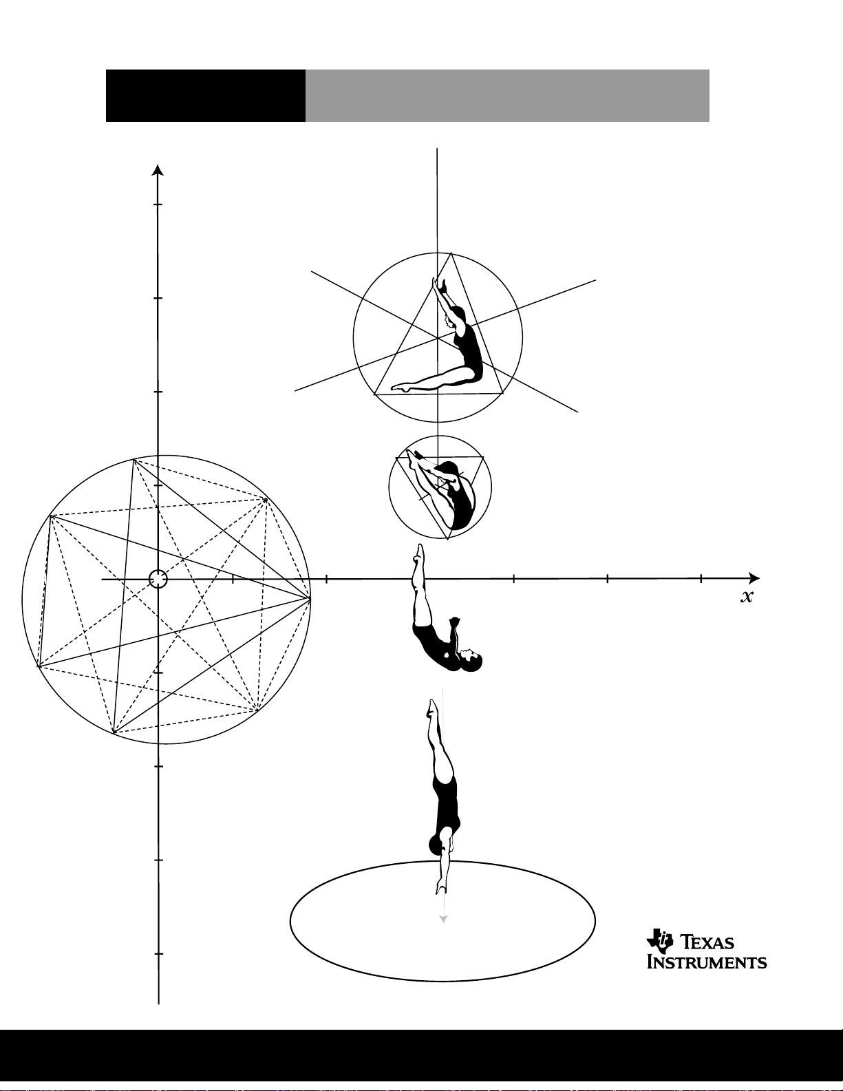
Dive into Geometry
Page 4

About Cabri Geometry II
Cabri Geometry II lets you construct and explore geometric objects interactively.
Jean-Marie Laborde and Franck Bellemain developed Cabri Geometry II at the Institut
d'Informatique et Mathématiques Appliquées de Grenoble (IMAG), a research lab at the Université
Joseph Fourier in Grenoble, France, in cooperation with the Centre National de la Recherche
Scientifique (CNRS) and Texas Instruments.
Texas Instruments, the publisher for Cabri Geometry II in the United States and Canada, is pleased
to bring computer-based geometry to classrooms. The geometric foundation of this easy-to-use
software encourages exploring and conjecturing—from simple shapes to advanced projective and
hyperbolic geometry.
About the Developers
Jean-Marie Laborde is founder and Research Director of Laboratoire de Structures Discrètes et de
Didactique (LSD2), a research laboratory within IMAG. He graduated in mathematics at Ècole
Normale Supérieure in Paris in 1969. He earned a Ph.D. (Thèse d'État) in computer science at the
University of Grenoble in 1977. Jean-Marie began work on the Cabri II project in 1981 as an
environment for graph theory. He has devoted his research efforts to the use of geometric methods
for the study of different classes of graphs, especially hypercubes.
Franck Bellemain earned a Ph.D. in mathematics at the Université Joseph Fourier in 1992. He
began work on the Cabri II project in 1986 and is responsible for writing several versions of the
software for Macintosh, PC-compatible, and Japanese computers. His research and thesis have
been devoted to the use of technology in the classroom.
Cabri Geometry II Features
¦ Includes interactive analytic, transformational, and Euclidean geometry.
¦ Allows intuitive construction of points, lines, triangles, polygons, circles, and other basic
objects.
¦ Translates, dilates, and rotates geometric objects around geometric centers or specified points
plus reflection, symmetry, and inverse of the objects.
¦ Constructs conics easily, including ellipses and hyperbolas.
¦ Explores advanced concepts in projective and hyperbolic geometry.
¦ Annotates and measures figures (with automatic updating).
¦ Uses both Cartesian and polar coordinates.
¦ Provides for user display of the equations of geometric objects, including lines, circles,
ellipses, and coordinates of points.
¦ Allows the user to create macros for frequently repeated constructions.
¦ Lets the teacher configure tool menus to focus student activities.
¦ Checks geometric properties to test hypotheses based on Euclid’s five postulates.
¦ Hides objects used in constructions to reduce screen clutter.
¦ Differentiates objects through the use of paint-like color and line palettes.
¦ Computes a locus continuously.
¦ Illustrates the dynamic characteristics of figures through animation.
¦ Allows the user to save drawings and macros to disk.
¦ Opens geometry constructions created on the TI-92.
¦ Provides one square meter of full-size work space, and prints the 8.5 by 11.0 inches (21.59 by
27.94 cm) drawing area.
Copying permitted provided TI copyright notice is included
© 1997, 1999 Texas Instruments Incorporated
Page 5

About Cabri Geometry II
Cabri Geometry II lets you construct and explore geometric objects interactively.
Jean-Marie Laborde and Franck Bellemain developed Cabri Geometry II at the Institut
d'Informatique et Mathématiques Appliquées de Grenoble (IMAG), a research lab at the Université
Joseph Fourier in Grenoble, France, in cooperation with the Centre National de la Recherche
Scientifique (CNRS) and Texas Instruments.
Texas Instruments, the publisher for Cabri Geometry II in the United States and Canada, is pleased
to bring computer-based geometry to classrooms. The geometric foundation of this easy-to-use
software encourages exploring and conjecturing—from simple shapes to advanced projective and
hyperbolic geometry.
About the Developers
Jean-Marie Laborde is founder and Research Director of Laboratoire de Structures Discrètes et de
Didactique (LSD2), a research laboratory within IMAG. He graduated in mathematics at Ècole
Normale Supérieure in Paris in 1969. He earned a Ph.D. (Thèse d'État) in computer science at the
University of Grenoble in 1977. Jean-Marie began work on the Cabri II project in 1981 as an
environment for graph theory. He has devoted his research efforts to the use of geometric methods
for the study of different classes of graphs, especially hypercubes.
Franck Bellemain earned a Ph.D. in mathematics at the Université Joseph Fourier in 1992. He
began work on the Cabri II project in 1986 and is responsible for writing several versions of the
software for Macintosh, PC-compatible, and Japanese computers. His research and thesis have
been devoted to the use of technology in the classroom.
Cabri Geometry II Features
¦ Includes interactive analytic, transformational, and Euclidean geometry.
¦ Allows intuitive construction of points, lines, triangles, polygons, circles, and other basic
objects.
¦ Translates, dilates, and rotates geometric objects around geometric centers or specified points
plus reflection, symmetry, and inverse of the objects.
¦ Constructs conics easily, including ellipses and hyperbolas.
¦ Explores advanced concepts in projective and hyperbolic geometry.
¦ Annotates and measures figures (with automatic updating).
¦ Uses both Cartesian and polar coordinates.
¦ Provides for user display of the equations of geometric objects, including lines, circles,
ellipses, and coordinates of points.
¦ Allows the user to create macros for frequently repeated constructions.
¦ Lets the teacher configure tool menus to focus student activities.
¦ Checks geometric properties to test hypotheses based on Euclid’s five postulates.
¦ Hides objects used in constructions to reduce screen clutter.
¦ Differentiates objects through the use of paint-like color and line palettes.
¦ Computes a locus continuously.
¦ Illustrates the dynamic characteristics of figures through animation.
¦ Allows the user to save drawings and macros to disk.
¦ Opens geometry constructions created on the TI-92.
¦ Provides one square meter of full-size work space, and prints the 8.5 by 11.0 inches (21.59 by
27.94 cm) drawing area.
Copying permitted provided TI copyright notice is included
© 1997, 1999 Texas Instruments Incorporated.
Getting Started with Cabri Geometry II 3
Page 6

4 Getting Started with Cabri Geometry II
Copying permitted provided TI copyright notice is included
© 1997, 1999 Texas Instruments Incorporated
Page 7

Getting the Most from Getting Started
About the Getting Started Guide
The Getting Started guide introduces you to Cabri Geometry II with hands-on exercises. However,
it does not cover all features of Cabri II, nor does it demonstrate all the ways to construct any
particular object. Getting Started includes the following sections:
First Steps
This section provides system requirements and installation instructions for Cabri Geometry II and
briefly discusses the Cabri Geometry II tools.
Checking System Requirements.
Macintosh systems
Installing Cabri Geometry II.
Starting Cabri Geometry II.
Cabri Geometry II Desktop.
Quick Reference Sheet.
Geometry II toolbar
Basic Operations
This section provides step-by-step exercises that give you hands-on experience with several
features basic to the construction of geometric objects using Cabri Geometry II. To quickly learn
Cabri Geometry II, complete these four exercises.
Modeling: Handshakes.
problem for pattern recognition
Exploring: Transformations in the Coordinate Plane.
reflection, rotation, and dilation around the x and y axes
Exploring: Power (Steiner) of a Point Problem.
Euclid, and then move the point to calculate various powers and record them in a table
Describes requirements for Windows, DOS, and
.....................................................................
Explains how to install Cabri Geometry II
Explains how to start Cabri Geometry II
Briefly describes the Cabri Geometry II screen and toolbar
....................
......................
......
Gives a list of the tools under each toolbox in the Cabri
....................................................................
Use a circle, points, and line segments to model a real-world
.........................................................
Construct a triangle, and explore
...................................
Construct a point as described by
.......
6
6
7
8
9
11
18
25
Constructing a Macro: Pentagram.
Create a pentagram by inscribing pentagons to
illustrate some important features of macros.
Menu Options and Toolbar Commands
Menu Options.
Toolbar Commands.
and a brief description about the operation of each tool
Note: Most of the illustrations in this guidebook are from the Macintosh version of Cabri
Geometry II; several are from the Windows and DOS versions. Due to space limitations, we could
not show every illustration for each version. Therefore, some illustrations in this guidebook may
be slightly different on your computer.
Copying permitted provided TI copyright notice is included
© 1997, 1999 Texas Instruments Incorporated.
Provides a quick reference and brief description of the menu options
Provides a quick reference to the tools available on each toolbar
............................................
........
....................................
Getting Started with Cabri Geometry II 5
32
38
40
Page 8

First Steps
Checking system requirements
Macintosh DOS
¦ Macintosh Classic or better.
¦ System 6.0 or later.
¦ 1 Mb available RAM for a Macintosh
Classic. (Memory requirements will be
greater for color or larger monitors than on
the Classic.)
¦ Hard disk with 1.2 Mb available for
program and demonstration files.
Windows 3.1 Windows 95
¦ 386 PC or better required; 486DX
recommended.
¦ PC must be in 386-Enhanced mode with
Virtual Memory enabled.
¦ VGA, SVGA video adapter and a color
monitor.
¦ 6 Mb RAM (minimum) memory installed.
¦ 7 Mb available hard disk space for program,
demonstration files, and system extensions.
¦ Mouse, or an equivalent pointing device.
Installing Cabri Geometry II
¦ DOS-compatible computers (PCs), 386 or
better, and running MS-DOS 3.3 or later.
¦ EGA, VGA, SVGA video adapter and a color
monitor.
¦ 3 Mb RAM (minimum) memory installed.
¦ Hard disk with 2.5 Mb available for
program and demonstration files.
¦ Mouse, or an equivalent pointing device.
¦ 386 PC or better required; 486DX
recommended.
¦ VGA, SVGA video adapter and a color
monitor.
¦ 6 Mb RAM (minimum) memory installed.
¦ 2 Mb available hard disk space for program
and demonstration files.
¦ Mouse, or an equivalent pointing device.
Macintosh DOS
1. Create a folder named
Cabri II
on your hard
disk.
2. Insert the Cabri Geometry II Macintosh
diskette in your floppy disk drive.
3. Double-click on the
Installer
on the diskette
and follow the directions on the screen.
Windows 3.1 Windows 95
1. Insert the Cabri Geometry II Windows
diskette #1 in your floppy disk drive.
RUN
2. From Program Manager, click on
enter
A:\SETUP
, and then follow the screen
and
prompts.
Installing Cabri Geometry II on a network
If you have purchased the network license for Cabri Geometry II, you may run the software on
your network. Use network procedures that are compatible with your network to install Cabri
Geometry II. See your Macintosh, Windows, or DOS User’s manual or your network
documentation for more information, if necessary.
Note:
Cabri Geometry II is supplied on high-density diskettes. If your computer will not accept these
diskettes, call, 1-800-TI-CARES and a service representative will supply you with low density diskettes.
1. Insert the Cabri Geometry II DOS diskette
in your floppy disk drive.
2. At the DOS prompt, enter:
A:\INSTALL
B:\INSTALL
or
, and then
follow the screen prompts.
1. Insert the Cabri Geometry II Windows
diskette #1 in your floppy disk drive.
2. Click on
START/RUN
and enter
A:\SETUP
,
and then follow the screen prompts.
6 Getting Started with Cabri Geometry II
Copying permitted provided TI copyright notice is included
© 1997, 1999 Texas Instruments Incorporated
Page 9

Installing Cabri Geometry II on a network
(continued)
Macintosh and DOS
1. Install Cabri Geometry II on the network server using the instructions given on the previous
page.
2. Run the program from the server the first time, and enter the requested information.
3. To run Cabri Geometry II on each network client, go to the directory on the network server
where the Cabri Geometry II application is installed. Macintosh users may double-click on
the Cabri II icon; DOS users may run Cabri2.exe to start the program.
The procedure described below, for Windows users, allows multiple client computers to run Cabri
Geometry II using the application software installed on the network server. Each client computer
is provided with the necessary system files to run Cabri Geometry II and a shortcut icon that is
linked to the application file on the network server.
Windows 3.1 and Windows 95
1. Install Cabri Geometry II on the network server using the instructions given on the previous
page. In the
Select Destination
screen, you must select a directory that will be accessible from each
client computer on the network.
2. Temporarily copy
setup.exe
and
setup.w02
from the installation diskettes to the same directory in
which you installed Cabri Geometry II in step 1.
3. On each network client, go to the directory on the network server that contains
double-click to on this file to run the setup program.
4. In the
Select Destination Directory
screen, click on the
that you used in step 1. Make sure the correct directory is displayed at the top of the window.
You may edit the path, if necessary, and then click on
already exists.
5. In the
Select Components
screen, deselect the first three components. The installation program
will determine if the fourth component is necessary for Windows 3.1x users.
6. When Cabri Geometry II has been installed on all client computers, delete the two files that
were temporarily copied to the network server in step 2.
setup.exe
Browse
button and select the same directory
OK
. Ignore the message that the directory
and
Starting Cabri Geometry II
Macintosh DOS
You can use one of four methods to start the
software on a Macintosh:
¦ Use
Open
¦ Double-click on the
¦ Double-click on any Cabri Geometry II
construction file, tool configuration file, or
macro file.
¦ Drag and drop any construction file onto
Cabri II
the
Windows
Double-click on the
Copying permitted provided TI copyright notice is included
© 1997, 1999 Texas Instruments Incorporated.
Finder
in the
.
Cabri II
icon.
icon (System 7 users only).
Cabri II
icon.
Type
CABRI
and press
ENTER
from the DOS
prompt directory where the Cabri Geometry II
files are located.
(Optional) Add the Cabri directory to your DOS
path to open Cabri Geometry II from any
directory.
Getting Started with Cabri Geometry II 7
Page 10
First Steps
y
y
(Continued)
About Cabri Geometry II Tools
In Cabri Geometry II, you use one construction tool at a time. The tools are displayed as groups of buttons
on the toolbar across the top of the screen. The buttons, often called “toolboxes,” are referenced from left
to right in the text.
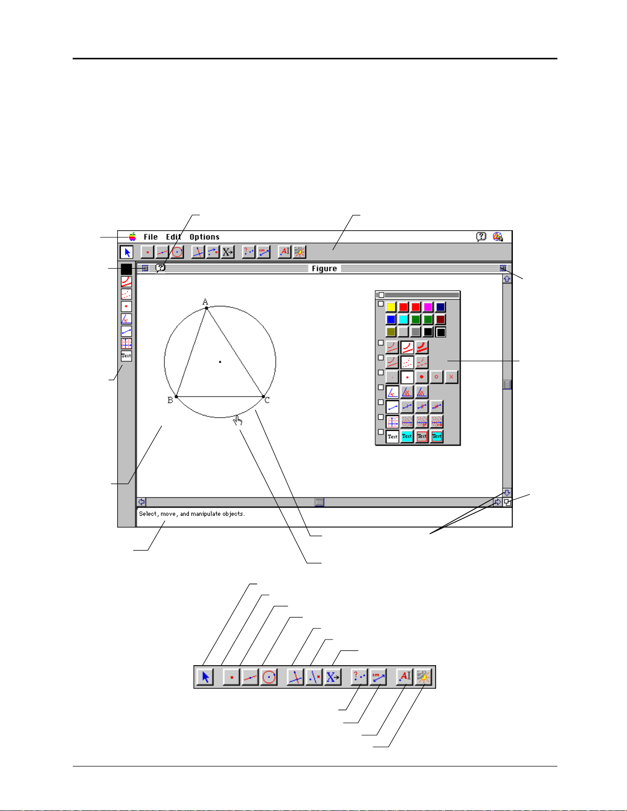
Cabri Geometry II Screen
The screen shown below illustrates the Macintosh version. Screens on Windows and DOS systems are
similar but slightly different.
Menu
Bar
Close
Box
Attribute
Icons
Drawing
Window
Help Icon
Toolbar
Zoom
Box
Attribute
Palette
This circle
Size
Box
Pointer Message
Help Window
Selection Pointer
Cabri Geometry II Toolbar
Pointer
Points
Lines
Curves
Construct
Transform
Check Propert
Measure
Displa
Draw
8 Getting Started with Cabri Geometry II
Scroll Bars
Macro
Copying permitted provided TI copyright notice is included
© 1997, 1999 Texas Instruments Incorporated
Page 11
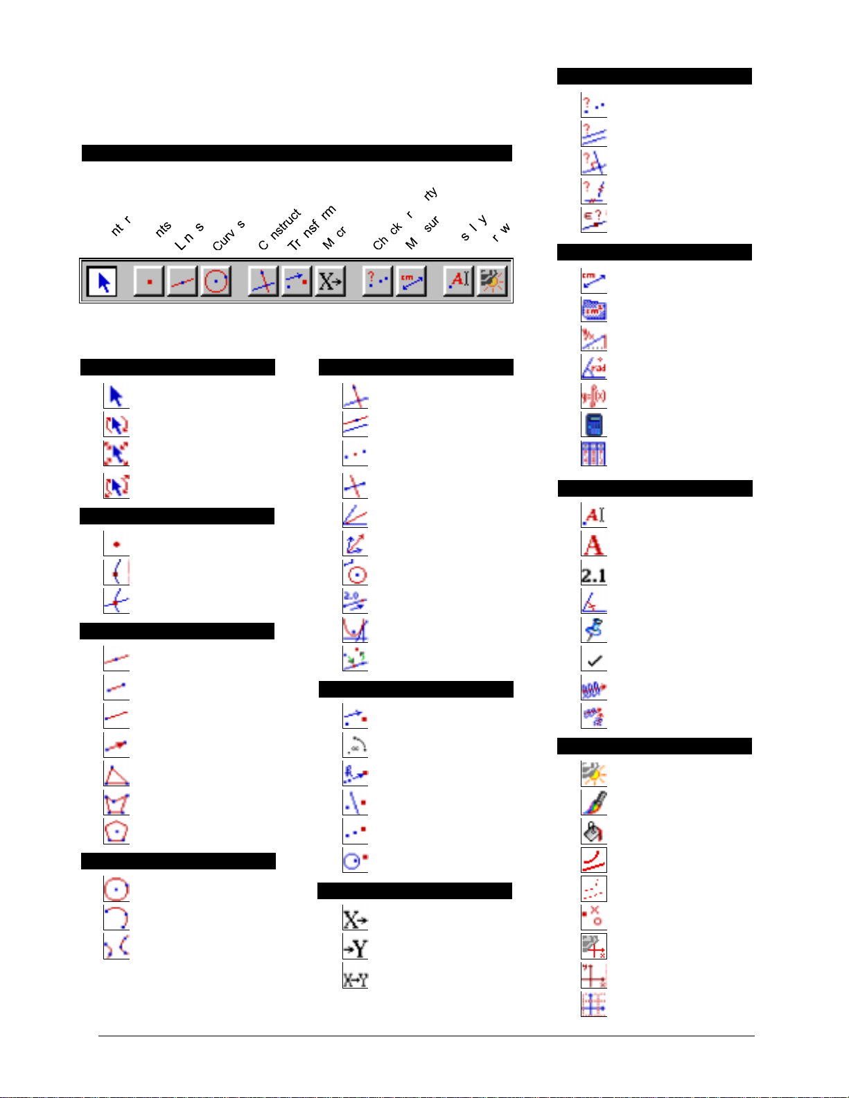
QUICK REFERENCE SHEET:
CHECK PROPERTY
CABRI GEOMETRY II
CABRI TOOLBAR
Pointer Perpendicular Line Equation and Coordinates
Rotate Parallel Line Calculate
Dilate Midpoint Tabulate
Rotate and Dilate Perpendicular Bisector
Collinear
Parallel
Perpendicular
Equidistant
Member
MEASURE
Distance and Length
Area
Slope
CONSTRUCTPOINTER
Angle
DISPLAY
POINTS
Point Vector Sum Comments
Point on Object Compass Numerical Edit
Intersection Point Measurement Transfer Mark Angle
LINES
Line Redefine Object Trace On/Off
Segment Animation
Ray Translation Multiple Animation
Vector Rotation
Triangle Dilation
Polygon Reflection Color
Regular Polygon Symmetry Fill
CURVES
Circle Dotted
Angle Bisector Label
Locus Fix/Free
TRANSFORM
DRAW
Hide/Show
Inverse Thick
MACRO
Arc Initial Object Modify Appearance
Conic Final Object
Define Macro New Axes
Copying permitted provided TI copyright notice is included
© 1997, 1999 Texas Instruments Incorporated.
Getting Started with Cabri Geometry II 9
Show/Hide Axes
Define Grid
Page 12

10 Getting Started with Cabri Geometry II
Copying permitted provided TI copyright notice is included
© 1997, 1999 Texas Instruments Incorporated
Page 13
Modeling: Handshakes
Problem: Four friends meet at a party. Each
wants to shake hands with the others. How many
handshakes take place? A fifth friend enters the
room—then a sixth and seventh. How many
handshakes are there?
You can use Cabri Geometry II to model this
situation by constructing points on a circle to
represent the friends and line segments to
People New handshakes Total handshakes
4
5
6
7
n
represent the handshakes.
Step-by-step instructions are given below. Follow the steps and fill in the chart at the right. Do you see a
pattern?
Get ready
1. Start Cabri Geometry Geometry II. Click anywhere in the
drawing window to remove the initial screen. The drawing
window appears.
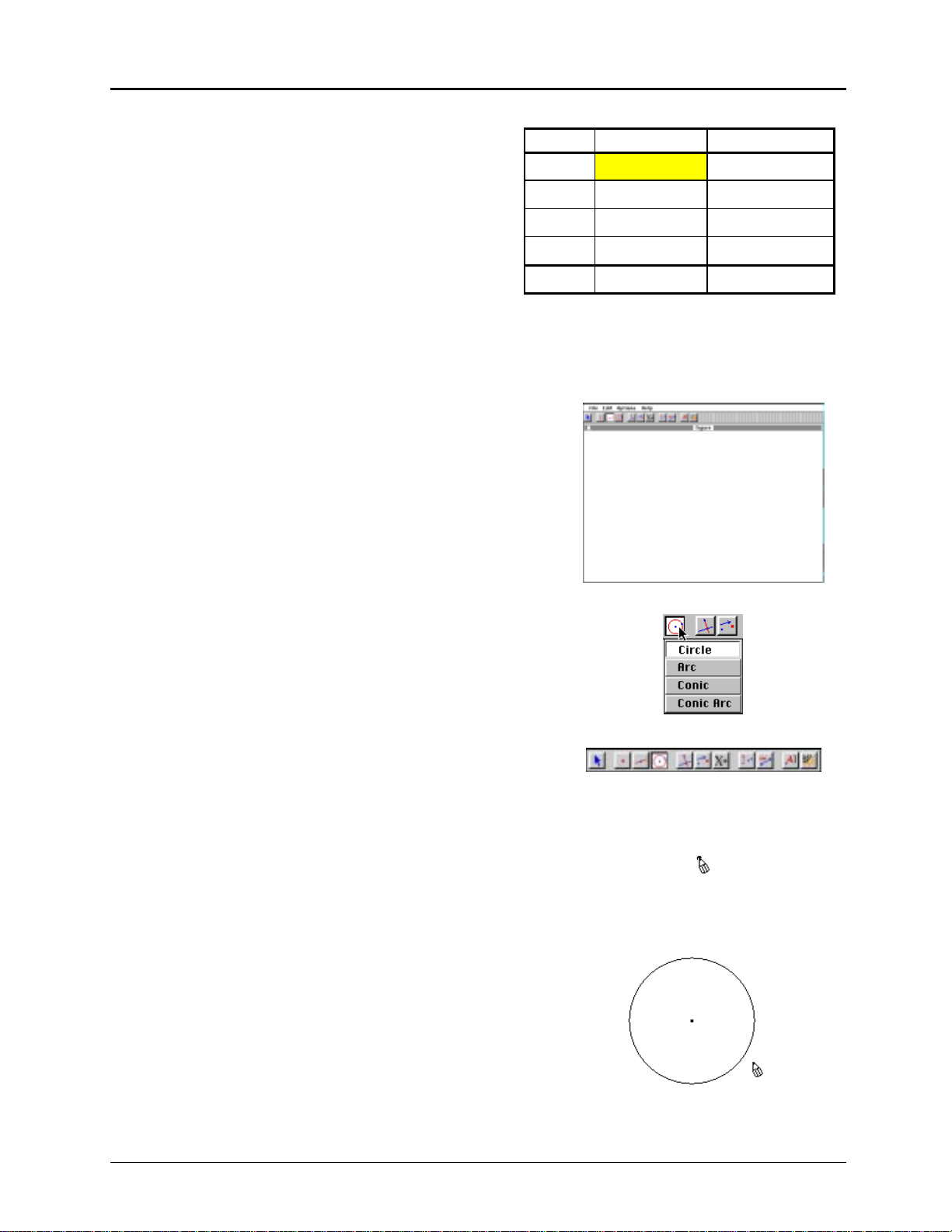
Construct a circle to represent the party
2. The fourth button on the toolbar represents the currently
Curves
selected tool in the
been assigned names for convenience—the names do not
appear on the screen.) Click and hold on that tool to pull
down the menu of tools used to construct curved lines.
3. Point to and click on the
the toolbox. Notice that this button is lighter than the others
and has the appearance of a button that is pushed in. This
Circle
tells you that
is the currently selected tool.
4. Move the " (pointer) toward the center of the drawing
window. As you move the " onto the drawing window, it
changes to a # (pencil) so that you can “draw” a circle. Click
and release the mouse button. A dot appears.
5. Move the # away from the point. (Do not hold the mouse
button down.) As you move the #, a circle appears. Continue
to move the # to change the size of the circle. When the
radius of the circle is about two or three inches, click again.
Notice that the
Circle
you can make another circle immediately, without having to
select from the toolbar again.
toolbox. (The toolboxes have
Circle
. The circle tool is displayed in
tool is still highlighted, indicating that
Copying permitted provided TI copyright notice is included
© 1997, 1999 Texas Instruments Incorporated
Getting Started with Cabri Geometry II 11
Page 14
Modeling: Handshakes
(Continued)
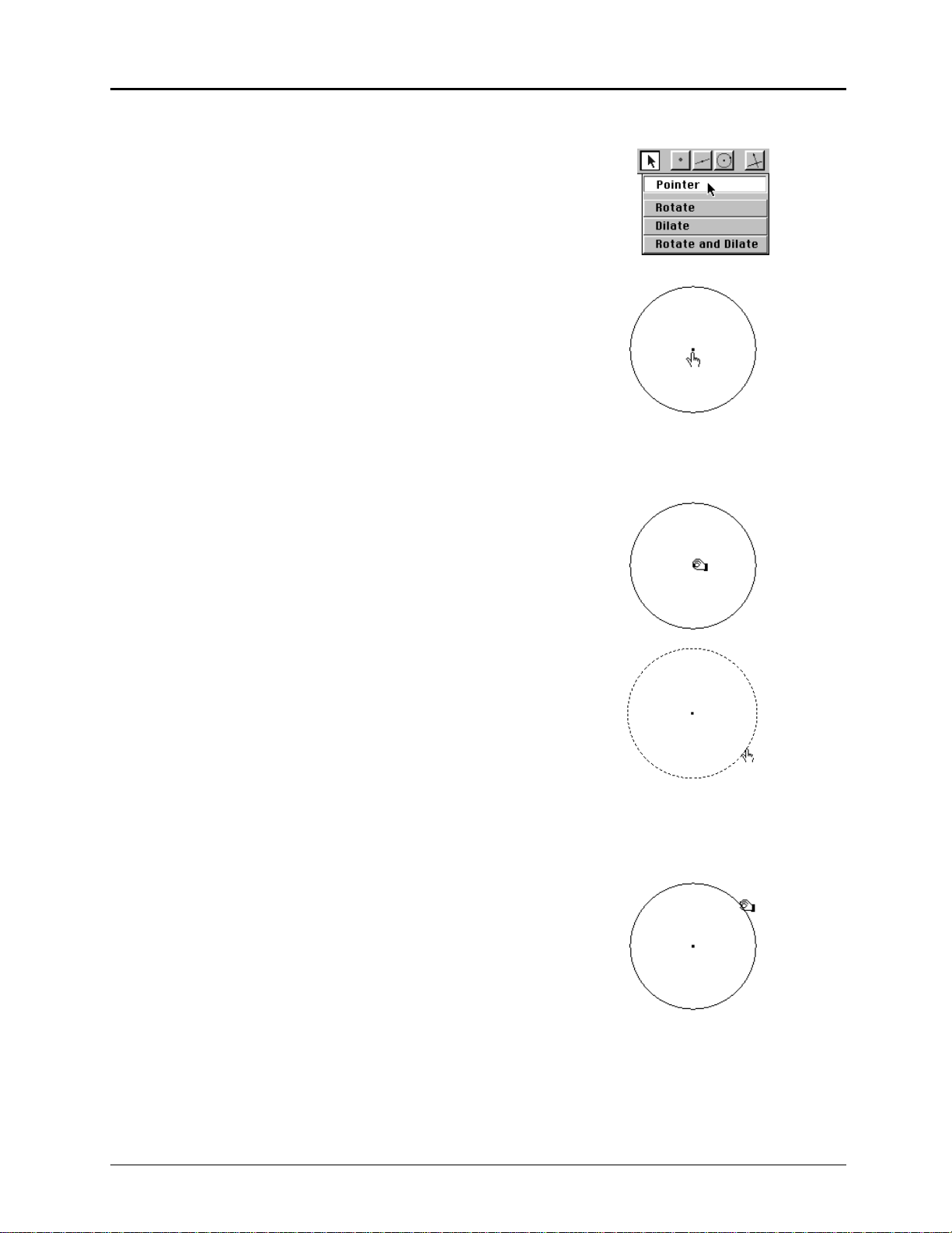
Move and resize the circle
6. Instead of making another circle, practice moving and
resizing the circle. The tools for moving and resizing are in
Pointer
the
Begin by pulling down the
select the
7. Move the " into the drawing window. Notice that the "
changes to a ! (cross hair). Move the ! to the point at the
center of the circle. It changes to a $ (pointing hand) and
the message
Cabri Geometry II recognizes all the objects you create and
informs you when the cursor is close enough to an object
for you to select it or perform some other activity.
Click once on the mouse button. The point flashes,
indicating that the point is selected.
8. Click and hold the mouse button. The $ changes to a %
(grasping hand) to show that you can move the object.
While holding the mouse button down, drag the point
toward the right to move the circle. Release the mouse
button. (Note: You don’t have to select a point to move it.)
toolbox, which is the first toolbox on the toolbar.
Pointer
toolbox; then point to and
Pointer
tool (").
This point
appears.
This point
9. Now move the $ away from the center point. It changes
back into a !. Move the ! toward the circumference until it
changes to the $ with the message
This circle
.
Click once on the mouse button. (Do not hold the mouse
button down.) The circumference appears to be moving or
flashing. This marquee outline indicates that the
circumference is selected.
To deselect the circle, move the $ until it changes to a !
and then click. The circumference no longer appears to be
moving.
10. Move the ! near the circumference until the $ appears.
Click and hold the mouse button. The $ changes into a %.
Enlarge the circle to fill the screen by dragging the
circumference. Release the button.
This circle
12 Getting Started with Cabri Geometry II
Copying permitted provided TI copyright notice is included
© 1997, 1999 Texas Instruments Incorporated
Page 15

Construct points to represent the four friends
11. The second button on the toolbar shows the currently
selected tool in the
and select the
Point
Points
toolbox. Pull down the
tool.
Points
menu
12. Pull down the
Attributes
(Macintosh, Windows)
Options
menu above the toolbar. Select
Hide/Show Attributes
Show
(DOS).
Macintosh and
Windows only
The attribute icons appear vertically on the left side of the
drawing screen. These icons represent tools that let you
control the appearance of objects that you create.
13. The fourth attribute icon represents the currently selected
Point
attribute. Click and hold the button to display the
choices. You can construct a point as a
•
, •, •, ™, or ×
.
Select the ™ attribute. Now every point that you construct
Point
with the
tool will appear on the drawing screen as a
until you change the attribute.
™
14. Move the # toward the circumference until the pencil
changes appearance and the message
On this circle
appears.
This message tells you that the defined point will be
attached to the circle and that, if you move the circle, the
point will move with it.
™
Click to create a
to represent the first friend.
15. Add the other three friends in the same way, evenly spaced
around the circle.
To check your work, complete the Checkpoint #1
instructions on the next page.
Copying permitted provided TI copyright notice is included
© 1997, 1999 Texas Instruments Incorporated
On this circle
Getting Started with Cabri Geometry II 13
Page 16

Modeling: Handshakes
(Continued)
Checkpoint #1: The first time you use the tools, you
may inadvertently create points that appear to be on the
circle but are only very near the circle. To check for
this:
a. Select the
Pointer
tool (") from the
Pointer
toolbox (first
button).
b. Drag the point at the center of the circle. All points
should move with the circle.
c. If a point is not on the circle, move the ! toward
that point until the $ appears and then click to
select the point. Press the
Point
tool and create a new point on the
DELETE
key. Select the
circumference of the circle.
Write the name of a friend next to each point
16. Select the
Label
tool from the
Move the ! toward one of the points until it changes to an I
(I-beam) and the message
Click once; the text box appears. (It may take more time
than you expect for the text box to appear.)
Display
This point
toolbox (tenth button).
appears.
This point
Type the name of the first friend.
Note: You can resize the text box by dragging the bottom
right corner.
17. Move the I (which changes to a !) toward another point
until it changes back to an I and the message
This point
appears. Click once. Type the second name in the text box.
Repeat for the other friends.
Pointer
Note: You can use the
tool (first button) to drag the
labels for better visibility.
14 Getting Started with Cabri Geometry II
Copying permitted provided TI copyright notice is included
© 1997, 1999 Texas Instruments Incorporated
Page 17

Construct the line segments to represent the handshakes
18. Select the
Segment
tool from the
Lines
toolbox (third button).
19. Move the # near a point representing a friend until the #
changes to a $ and the message
This point
appears. Click
once. (Do not hold the mouse button.)
Move the # away from the point. A line extends from the
point. Move the # toward another point until the $ and the
message
This point
appear. Click again. The line segment
(handshake) is defined by the two end points (friends).
Caution: Do not click when the # is displayed with the
message
Point on this object
because this will create a new
point. If you do create a new point inadvertently, refer to the
steps in the Checkpoint #1 box to delete it.
20. Repeat step 19 to create line segments to model all possible
handshakes.
Checkpoint #2: Check to see that you have not
inadvertently created new points as the end points of the
line segments.
a. Select the
Pointer
tool (") from the
Pointer
toolbox (first
button).
b. Drag one of the points on the circle about one-half of an
inch (1.3 cm). The point (and its associated label)
should move around the circumference, moving all of its
line segments with it.
c. Repeat for the other points.
Note: If the cursor changes to a magnifying glass and the
message
Which object?
appears, you may have created
duplicate points and one or more line segments are not
attached to an original point. To start over, press
COMMAND+A
(Macintosh) or
CTRL+A
(Windows, DOS) on
your keyboard to select all objects on the screen, and then
press
DELETE
. A clean drawing window appears. Repeat the
exercise. It will go very quickly now that you are familiar
with the Cabri Geometry II tools!
Copying permitted provided TI copyright notice is included
© 1997, 1999 Texas Instruments Incorporated
Getting Started with Cabri Geometry II 15
Page 18

Modeling: Handshakes
(Continued)
Count and record the handshakes
21. To keep track of each handshake as you count it, use the
selection feature. Click on the first line, and then press and
as you click on each additional line. The change
SHIFT
hold
in appearance of each line helps you keep track as you
count.
Enter the number in the chart at the beginning of the
exercise. Click outside the circle to deselect the lines.
Open the on-screen attribute palette
22. You can help differentiate new points and handshakes from
the old points and handshakes by using the color, point, and
line attributes.
For convenience, you can create a customized on-screen
attribute palette of the attribute icons.
Click and hold on the
on the attribute toolbar); however, instead of selecting a
color when the palette opens, hold down the mouse button
and drag the entire palette onto the drawing window.
Release the mouse button.
Click on each of the attribute buttons on the vertical
attribute toolbar to add the tools to the on-screen attribute
palette. These include color, line thickness, line appearance,
point type, and others.
Note: On monochrome systems, the color palette is not
available. On these systems, the palette presents varied
shades of gray.
You can drag the palette by its title bar to a more convenient
location on the drawing window. You can close any
unneeded attribute toolbox by clicking on the close box at
the left corner of that toolbox.
Color Attribute
toolbox (the top button
16 Getting Started with Cabri Geometry II
Copying permitted provided TI copyright notice is included
© 1997, 1999 Texas Instruments Incorporated
Page 19

Add the fifth friend and handshakes
23. Select the
Notice that
Point
tool from the
™
and the color red are selected on the palette.
Points
toolbox (second button).
(Each time you select a new tool, the palette shows the
current settings for that tool.)
24. Select a different color and x as the
Point Attributes
for the
fifth friend. Then add the new friend to the circle. Select
Label
from the
Display
toolbox (tenth button). Move to the
new point, click once, and type the friend’s name. You can
Pointer
use the
tool (first button) to enlarge the circle and
reposition the points and labels as needed for visibility.
Note: You can label a point when you create it by typing the
name on the keyboard immediately after creating the point.
However, this labeling method is limited to five characters.
25. Select the
Segment
tool from the
Choose a different color and a different
Lines
toolbox (third button).
Line Attribute
a dotted line or a heavier weight.
Add the new handshakes. (Remember to click only when
the message says
This point
so that you don’t create a new
point.)
Count the handshakes, and enter the results on the chart at
the beginning of the exercise.
, such as
Add the sixth and seventh friends and handshakes
26. Add the additional friends and the associated handshakes.
Change the line color and attribute for each.
Count the handshakes, and complete the chart.
Do you see a pattern? Can you predict how many handshakes
there are for eight friends? For 20 friends? Generalize the
equation.
Solution: The total handshakes are 6, 10, 15, and 21, requiring 4, 5, and 6 new handshakes for the fifth,
sixth, and seventh friends, respectively. In general, the number of new handshakes required is n–1, and the
total number of handshakes is n(n–1)à2.
Copying permitted provided TI copyright notice is included
© 1997, 1999 Texas Instruments Incorporated
Getting Started with Cabri Geometry II 17
Page 20

Exploring: Transformations in the Coordinate Plane
Problem: What happens to the Coordinate values of a triangle
that is constructed in the upper right quadrant and then transformed in various ways? Explore using Cabri Geometry II to
find out.
Get ready
1. Start the software (see page 1-3), if necessary, or select the
New
option from the
already displayed. You will be prompted to save your
current construction if one exists.
Display the rectangular coordinate axes
File
menu if the drawing window is
2. Select
Show Axes
axes appear, centered on the drawing screen.
from the
Draw
toolbox (last button). The
Construct a triangle
3. Select the
To construct a triangle, move the # and click once at each
vertex. The lines are drawn automatically as you define the
vertices. Make the triangle any shape you want, but put it in
the upper right quadrant.
Triangle
tool from the
Lines
toolbox (third button).
Display the coordinates for each vertex
4. Select the
toolbox (ninth button).
Move the # toward any vertex until the $ and the message
Coordinates of this point
appear near the point. Repeat for the remaining two vertices.
(Your coordinates may not match those shown here.)
5. Reposition the coordinates for better visibility. To do this,
select the
Move the ! toward one pair of coordinates until you see the
message
triangle. They momentarily “resist,” but then let you position
them anywhere on the drawing screen. Repeat the process
for the other coordinates.
Equation & Coordinates
appear. Click once. The coordinates
Pointer
tool from the
This number
. Drag the coordinates away from the
tool from the
Pointer
toolbox (first button).
Measure
Display the area of the triangle
6. Select
7. Use the
18 Getting Started with Cabri Geometry II
Area
from the
the # toward the triangle until the message
appears. Click once. The area is calculated and displayed.
Pointer
that you can see the measurement as you transform and
explore the triangle.
Measure
tool to reposition the area measurement so
toolbox (ninth button). Move
This triangle
Copying permitted provided TI copyright notice is included
© 1997, 1999 Texas Instruments Incorporated
Page 21

Transform and explore the triangle
8. Now use the
Pointer
tool to drag any one of the vertices. Drag
it into each of the other quadrants.
What happens to the coordinate values? To the area?
Return the vertex to the upper right quadrant.
9. Move the ! toward a side of the triangle. Because the
triangle was created as an object, the message
This triangle
appears. Drag the entire triangle into each of the quadrants.
What happens to the coordinate values? To the area?
Return the triangle to the upper right quadrant.
10. Select the
Rotate
tool from the
Pointer
toolbox (first button).
Drag the triangle (not a vertex), moving the cursor in a
circular motion. The entire triangle rotates around its
geometric center.
What happens to the area?
11. You also can rotate the triangle around a specified point.
Rotate
With the
the $ and the message
tool selected, move the ! to the origin until
This point
appear. Click on the
selected point. The selected point begins flashing. Move the
cursor toward the triangle. When the message
This triangle
appears, drag the triangle in a circular motion around the
origin.
What happens to the coordinate values? Does the area
change? Why or why not?
Copying permitted provided TI copyright notice is included
© 1997, 1999 Texas Instruments Incorporated
Getting Started with Cabri Geometry II 19
Page 22

Exploring: Transformations in the Coordinate Plane
(Continued)
Transform and explore the triangle
12. Select the
Dilate
tool from the
(continued)
Pointer
toolbox (first button).
Drag the triangle. If the origin is still selected, the triangle
dilates toward and away from the origin. What does this do
to the shape and size of the triangle?
Deselect the origin by clicking in a blank part of the drawing
screen. Now dilate the triangle. What happens this time?
(The triangle dilates around its geometric center.)
Explore reflections and symmetry
13. Drag the triangle back into the upper right quadrant, if
necessary.
Select the
Reflection
tool from the
button).
To reflect the triangle across the y axis, move the # until the
message
Reflect this triangle
appears. Click once. Move the # to
the y axis and click when the message
appears. The reflected triangle appears in the upper left
quadrant.
14. Select the
Equation & Coordinates
toolbox (ninth button), and add the coordinates to the
reflected triangle.
Transform
toolbox (sixth
with respect to this axis
tool from the
Measure
15. Select the
Pointer
tool from the
Pointer
toolbox (first button)
and try to drag the new triangle. What happens? Try to drag
the original triangle. What happens? (The reflected triangle
is dependent upon the original triangle and cannot be moved
independently.)
16. Select the
Symmetry
tool from the
Transform
toolbox (sixth
button). Point to and click on the triangle in the upper left
quadrant when the message
Reflect this triangle
click on the point at the origin when the message
to this object
appears. A triangle that is symmetric to the
appears. Then
with respect
origin appears in the lower right quadrant.
17. Add the coordinates to the reflected triangle with the
Equation & Coordinates
tool from the
Measure
toolbox (ninth
button).
18. Select the
Pointer
tool from the
Pointer
toolbox (first button),
and drag the triangle in the upper right quadrant into each of
the other quadrants.
20 Getting Started with Cabri Geometry II
Copying permitted provided TI copyright notice is included
© 1997, 1999 Texas Instruments Incorporated
Page 23

Construct a polygon
19. Open a new drawing by selecting
New
from the
20. Display the coordinate system by selecting the
tool from the
21. Select the
Draw
Polygon
toolbox (last button).
tool from the
Lines
toolbox (third button).
File
menu.
Show Axes
Construct a four-sided polygon in the upper right quadrant
by moving the # and clicking once at each vertex. Make it
any shape you want. The last vertex must be the same as the
first. Click when the message
This point
appears.
Translate the polygon
22. You can translate an object according to a selected vector.
Vector
Select
from the
# and click once in the upper right quadrant to create the tail
of the vector, and move the # and click again to create the
head of the vector.
23. Select the
Translation
button).
Click on the polygon when the message
appears, and then click on the vector when the message
this vector
appears. The translated polygon appears, offset
from the original polygon by the direction and length
(magnitude) of the vector.
Lines
toolbox (third button). Move the
tool from the
Transform
toolbox (sixth
Translate this polygon
by
24. Drag the head of the vector when the cursor changes to $
and the message
Translate this point
appears. The translated
polygon follows the head of the vector.
25. Using the
Pointer
tool from the
Pointer
toolbox (first button),
drag the original polygon. What happens to the translated
polygon?
Copying permitted provided TI copyright notice is included
© 1997, 1999 Texas Instruments Incorporated
Getting Started with Cabri Geometry II 21
Page 24

Exploring: Transformations in the Coordinate Plane
(Continued)
Rotate a polygon by a defined angular value.
26. You can rotate a polygon by an angular value that you
define. This example begins with the value 30º.
First, remove the polygons created previously. To do this,
Pointer
select the
tool from the
Then press and hold the mouse button in a blank area
outside the polygons and vector. Drag the mouse across the
drawing until a marquee rectangle surrounds all of the
objects. Release the mouse button. All of the objects in the
rectangle are selected (except the axes, which cannot be
removed in this manner).
Press
DELETE
on your keyboard. The objects are removed.
Pointer
toolbox (first button).
27. Select the
Polygon
tool from the
Lines
toolbox (third button).
Construct a four-sided polygon in the upper right quadrant.
Make it any shape you want.
28. Select the
Numerical Edit
tool from the
Display
toolbox (tenth
button). Click at the location where you would like to place
the numerical value (you can place it anywhere in the
quadrant). A numerical edit window appears.
29. Type the value 30 in the numerical edit window. Then, press
U
(Macintosh) or
CTRL+U
(Windows, DOS). A list of units
appears in a pop-up menu.
Degree
Select the unit
. The degree symbol (°) is assigned to
the value 30.
22 Getting Started with Cabri Geometry II
Copying permitted provided TI copyright notice is included
© 1997, 1999 Texas Instruments Incorporated
Page 25

30. Select the
Rotation
tool from the
Transform
toolbox (sixth
button). Move the # toward the polygon until the message
Rotate this polygon
appears. Click to select the polygon.
31. Move the # toward the origin point until the message
this point
toward the value 30 until the message
appears. Click to select this point. Now move the #
using this angle
around
appears. Click to select the value. An image of the polygon
that is rotated 30 degrees around the origin point is created.
Dynamically change the rotation angle.
32. Select the
Numerical Edit
tool from the
button). Move the I (I-beam) towards the value 30 degrees
until the message
This number
appears. Click once to select
the value. A flashing cursor appears in the window next to
the number.
33. Press the ! (left arrow key) on your keyboard to position the
flashing cursor to the right of the 3. Now press the # (up
arrow key). Notice that the first digit increases by 1. (The
Numerical Edit
tool increases/decreases the digit to its left
when the up and down arrow keys are used.) Press the # (up
arrow key) until the value reads 90 degrees, noticing the
changes in the rotated polygon. Now, press the $ (down
arrow key). The digit decreases by 1.
You can change the rotation angle dynamically to any value
using this method. Alternatively, you can highlight the value
using the mouse and type in a new value.
Display
toolbox (tenth
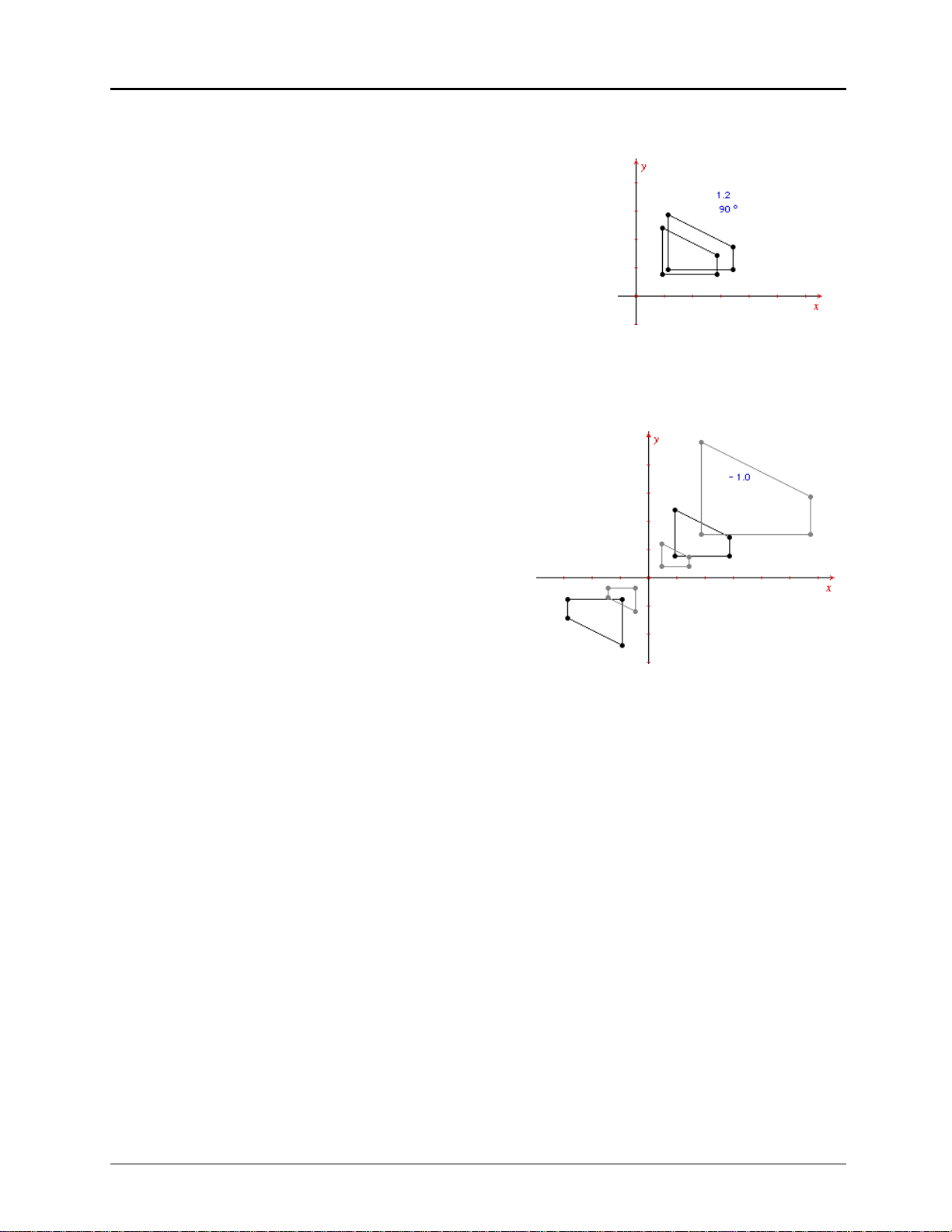
Dilate the polygon by a defined factor.
34. You also can dilate a polygon by a factor that you define.
This example begins with the factor 1.2.
Select the
Numerical Edit
tool from the
button), if necessary. Click at the location where you would
like to place the numerical value (you can place it anywhere
in the quadrant). A numerical edit window appears.
1.2
35. Type the value
U
(Macintosh) or
in the numerical edit window. Then press
CTRL+U
(Windows, DOS) to see the list of
units.
Select the option
Without unit
. No unit is assigned to the value.
Display
toolbox (tenth
Copying permitted provided TI copyright notice is included
© 1997, 1999 Texas Instruments Incorporated
Getting Started with Cabri Geometry II 23
Page 26
Exploring: Transformations in the Coordinate Plane
(Continued)
Dilate the polygon by a defined factor
36. Select the
button). Move the # toward the original polygon until
the message
the polygon.
37. Move the # toward the origin point until the message
with respect to this point
Now move the # toward the value 1.2 until the message
using this factor
image of the polygon that is dilated by the factor 1.2
with respect to the origin point is created.
Dilation
tool from the
Dilate this polygon
appears. Click to select the point.
appears. Click to select the value. An
appears. Click to select
(continued)
Transform
toolbox (sixth
Dynamically change the dilation factor
38. Select the
(tenth button). Move the I (I-beam cursor) toward the
value 1.2 until the message
once to select the value. A flashing cursor appears in
the numerical edit window next to the number.
39. Use the left and right arrow keys on your keyboard as
necessary to position the flashing cursor to the right of
the 2. Press the # (up arrow key) until the value reads
2.0. Now press the $ (down arrow key) until the value
reads -1.0.
Numerical Edit
tool from the
This number
Display
toolbox
appears. Click
You can change the dilation factor dynamically to any
value using this method. Alternatively, you can
highlight the value using the mouse and type in a new
value.
Continue to explore by changing the numerical values in
various ways and comparing them with other
transformational methods in Cabri Geometry II.
24 Getting Started with Cabri Geometry II
Copying permitted provided TI copyright notice is included
© 1997, 1999 Texas Instruments Incorporated
Page 27

Exploring: Power (Steiner) of a Point Problem
Problem: A theorem which originally appeared in Euclid’s
Book III, Proposition 35 states the following: Given that a
secant intersects a circle at A and B, and that a second secant
intersects the circle at C and D, if the secants intersect at S,
BS = CS ∗ DS. This property was investigated by the
then AS
Swiss geometer Jakob Steiner (1796–1863) who first used the
term “power of the point” for this product.
Get ready
∗
1. Start the software, if necessary, or select the
File
from the
displayed. You will be prompted to save your current
construction if one exists.
menu if the drawing window is already
New
option
Construct a circle
2. Select the
To construct a circle, move the # and then click once to
create the center point. Move the mouse away. The outline
of the circle is drawn. Click again to specify the radius of the
circle.
Circle
tool from the
Curves
toolbox (fourth button).
Construct a point that lies within the circle
3. Select the
Move the # to a location inside the circle. Click once to
create a point. Then, type the letter
Point
tool from the
Points
toolbox (second button).
S
from the keyboard.
Construct two lines that intersect at S
4. Select the
Move the # toward the circle until the ' and the message
this circle
appears. Move the cursor toward the point
message
the point and complete the definition of the line.
Repeat this procedure to construct another line attached to
the circle that intersects the first line at
Note: The intersection point
can be moved freely about the construction. The two points
that are attached to the circle are independent points.
Independent points can be moved with respect to the object
to which they are attached. These types of points are in
contrast to dependent points which cannot be moved
directly. For a complete discussion of basic, independent,
and dependent points and objects, read Chapter 1: Basic
Operations in the Cabri Geometry II Guidebook.
Copying permitted provided TI copyright notice is included
© 1997, 1999 Texas Instruments Incorporated
Line
tool from the
appear. Click once. The initial point of the line
By this point
appears. Click once to attach the line to
Lines
toolbox (third button).
S
until the
S
.
S
is a basic object. That is, it
On
Getting Started with Cabri Geometry II 25
Page 28

Exploring: Power (Steiner) of a Point Problem
(Continued)
Modify the appearance of the construction
5. Select the
Modify Appearance
tool from the
Draw
toolbox (last
button). A pop-up screen showing the various appearance
attributes appears. Click on the large, solid point in the top
row.
If necessary, point to the top line of the pop-up screen and
hold down the mouse button to “drag” the pop-up screen
away from your drawing.
6. Move the ! toward point S until the ! changes to a 2 and
the message
This point
appears. Click once. The point
changes to a large point.
Repeat this procedure for the two independent points.
7. Click on the close box in the top left corner of the pop-up
screen to remove the screen from the drawing window.
Construct segments within the circle
8. Select the
Segment
tool from the
Move the # toward one of the independent points on the
circle until the message
This point
initial end point of the segment appears. Move the # toward
S
point
until the message
complete the segment construction.
Lines
appears. Click once. The
This point
appears. Click to
toolbox (third button).
This point
Repeat this procedure to construct a segment on the other
line.
9. Move the # toward point S until the message
This point
appears. Click once to create the initial end point of the
segment. Move the # toward one of the intersections of line
and circle until the message
Point at this intersection
Click to complete the segment construction.
Repeat this procedure to construct a segment on the other
line.
Point at this intersection
appears.
26
Getting Started with Cabri Geometry II
Copying permitted provided TI copyright notice is included
© 1997, 1999 Texas Instruments Incorporated
Page 29

Label the points
10. Select the
Label
tool from the
Display
toolbox (tenth button).
Move the ! toward one of large points on the circle until the
! changes to I (I-beam) and the message
This point
appears.
Click once. An edit window appears next to the point. Enter
A
the label from the keyboard. Call this point
.
Move the I toward the small point which is on the same line.
B
Click once to open the edit window. Call this point
.
11. Repeat step 10 for the two unlabelled points on the circle,
C
labeling them
and D.
Hide the lines
12. Hiding objects can often make a construction easier to read
visually as well as add an element of intrigue. Hiding the
lines will aid you in evaluating the intersecting chords.
Select the
Hide/Show
tool from the
Notice that the construction is redrawn quickly.
13. Move the ! toward a line until the message
Click once. The line becomes dotted. Move to the other line
and click. It also becomes dotted. These objects will be
hidden from view when you change to another tool.
Draw
toolbox (last button).
This line
appears.
Pointer
14. Select the
tool (first button).
You now have a construction similar to the one investigated
by Euclid over 2000 years ago!
Measure the lengths of the segments
15. Select the
Move the # toward segment
this segment
Distance & Length
tool from the
AS
until the message
appears. Click once to display the length of the
segment.
Immediately after the measurement is created, type
the keyboard. The measurement is now labeled.
16. Repeat step 15 for segments
BS, CS
need to adjust the positions of the displayed measurements
in order to read them more easily.
Note: Measurements also can be labeled using the
tool from the
Display
toolbox. Select
measurement. Enter a label in the edit window.
Measure
toolbox.
, and DS. You may
Comments
. Select the
Length of
AS:
from
Comments
Copying permitted provided TI copyright notice is included
© 1997, 1999 Texas Instruments Incorporated
Getting Started with Cabri Geometry II 27
Page 30

Exploring: Power (Steiner) of a Point Problem
(Continued)
Measure the lengths of the segments
(continued)
17. You may find it beneficial to group the measurements in one
location in order to inspect the values easily.
Select the
Pointer
tool from the
Pointer
toolbox. Drag each
measurement to an unoccupied area of the drawing window.
The measurement will hesitate initially when being dragged,
but will then follow the pointer.
Calculate the power of the point S
18. According to the theorem, AS * BS = CS * DS. Use the
Cabri II built-in calculator to verify this result.
Select
Calculate
from the
calculator appears at the bottom of the screen.
19. Move the # toward the measurement of
message
This number
measurement in the calculation. A marquee box appears
around the measurement along with an
a
20. The variable
also appears in the calculator edit window.
Now click on the multiplication ( * ) button. Next, select the
measurement of
BS
the equals (=) button. The result is displayed in the
calculator result window.
Measure
toolbox (ninth button). A
AS
until the
appears. Click once to include the
a
.
. To complete the calculation, click on
21. Move the result into the drawing window by clicking once
on the result window. An empty marquee box appears in the
drawing window. Move the # (pencil) to move the box to a
location near the measurements. Click to place the result.
Result
The calculation is tagged with the label
22. Select the
Comments
4 cursor toward the label
message
Edit this text
tool from the
Result:
appear. Click once to open an edit
Display
until the I (I-beam) and the
.
toolbox. Move the
window around the label and the measurement. Highlight
the label by dragging the cursor across the text, and then
enter a new label
AS * BS
23. Repeat steps 18–22 for
result to
CS * DS
.
.
CS
and DS. Change the label on the
Result: 3.93 cm
2
28
Getting Started with Cabri Geometry II
Copying permitted provided TI copyright notice is included
© 1997, 1999 Texas Instruments Incorporated
Page 31

Manipulate the construction to explore the results
24. Select the
Pointer
tool from the
Pointer
toolbox. Evaluate the
proposed theorem by manipulating the construction. As you
A
drag point
hold true? That is, do
25. Drag point
happens to the calculation results? Now drag point
point
26. Drag point
or point C around the circle, does the property
AS * BS
S
to a new location within the circle. What
C
around as before. Does the property still hold true?
S
to several locations within the circle while
and
CS * DS
remain constant?
A
and
monitoring the power of the point calculations. Make a list
of your observations.
A partial list of observations is shown at the end of this
exercise.
Construct a table
27. Construct a table of values to support your generalizations.
Select the
Tabulate
tool from the
button).
To define the size and location of your table, move the
pointer to an unoccupied location in the drawing window.
Press and hold the mouse button down. Move the cursor to
another location to draw a rectangle. Release the mouse
button. A table appears within the rectangle. If the size is
unsuitable, resize the table by dragging the lower right
corner.
Measure
toolbox (ninth
28. Select the values you want to tabulate (copy).
Move the # on top of the number you labeled as
the message
Tabulate this value
appears. Click once to place it
in the table for tabulation. The label and the current value
appear in the table.
Repeat this procedure for the value labeled
CS * DS
value is not visible, you must change the size of the table.
Only fully visible columns display results. Resize the table
by dragging the lower right corner.
AS * BS
. If this
until
Copying permitted provided TI copyright notice is included
© 1997, 1999 Texas Instruments Incorporated
Getting Started with Cabri Geometry II 29
Page 32

Exploring: Power (Steiner) of a Point Problem
(Continued)
Collect data to support the hypothesis
29. You may wish to record additional values to support the
hypothesis.
Select the
points
Pointer
A, C
, and S to manipulate the construction as you
wish. Press the
tool from the
key to record additional values in the
TAB
Pointer
toolbox. Drag the
columns defined.
Note: At least one value must change in order for a new row
of data to be recorded in the table. In this case, the value
may be the length of a segment which is included in the
calculation, although it is not visible in the table.
30. There are several ways in which to approach this problem.
This step examines one possible observation. You may wish
to explore other facets of the problem.
S
Drag point
of the circle. Press the
collect a new power of
on an imaginary line through the center point
key about every centimeter to
TAB
S
calculation.
Analyze the data
31. Notice that the powers of S are smaller the further away
S
from the center point you move point
S
as you keep point
within the circle. The opposite occurs
outside of the circle, although the property continues to
hold true.) Did any of the values repeat when you moved
S
point
across the circle?
. (This is true as long
If necessary, resize the table to view all of its contents. Drag
the table up the drawing window to see the lower rows.
30
Getting Started with Cabri Geometry II
Copying permitted provided TI copyright notice is included
© 1997, 1999 Texas Instruments Incorporated
Page 33

Modify the table and delete values from the table
32. Select
Tabulate
from the
Measure
toolbox.
Point to the table and click. An edit window encloses the
table.
Point to the first column of a row and click. (The first
column is the column which contains the numbers in
sequential order. Each number represents a row.) The entire
row appears in gray. Press the
DELETE
key to delete the
values in that row. The remaining values move up one row.
33. Point to the first row of a column and click. (The first row is
the row which contains the title of the column.) The entire
column appears in gray. Press the
DELETE
key to delete the
values in the column. The remaining columns move left.
Repeat to delete the values in the remaining columns.
Animate the construction
34. Animate the construction to record data in the table
automatically.
Select the
Animation
tool from the
move the ! until the message
Display
This table
appears to select the
toolbox. Next,
table. The table is enclosed in a marquee rectangle to
indicated it is selected.
35. Move the pointer to point
A
until the message
This point
appears. Press and hold the mouse button and move away
from the point. The animation spring is connected to the
point and the cursor. Release the mouse button to start the
animation. (The animation spring indicates the direction and
relative velocity of the animation.) Click again to stop the
animation.
Values are recorded in the table automatically.
There are many facets to this problem. We encourage you to
explore further.
Copying permitted provided TI copyright notice is included
© 1997, 1999 Texas Instruments Incorporated
Getting Started with Cabri Geometry II 31
Page 34

Constructing a Macro: Pentagonal Curve of Pursuit
Problem: Line designs created with colored thread can
produce attractive patterns. With Cabri II, line designs are
easy and fun. Some designs can be developed by inscribing
regular polygons within similar regular polygons. This can be
described as a series of two-step transformations. In this
example, we create a Pentagonal Curve of Pursuit by
inscribing pentagons to illustrate some important features of
macros.
Get ready
1. Start the software, if necessary, or select the
File
from the
menu. You will be prompted to save your
New
option
current construction if one exists.
Construct a segment
2. Select the
Segment
tool from the
To construct a segment, click once at each end point.
Construct a segment that is about 5 cm long.
Tip: If you press the
SHIFT
point, the slope of the segment is limited to 15-degree
increments.
Lines
toolbox (third button).
key after creating the first end
Divide the segment into eighths
3. Select the
Midpoint
tool from the
button).
Move the # toward the segment until the $ and the message
Midpoint of this segment
appear. Click once. The midpoint of
the segment appears. The segment is divided into halves.
4. To divide the segment into eighths, you need to divide the
segment into two more halves. That is, 1/2 * 1/2 * 1/2 = 1/8.
Use the
Midpoint
tool to perform the division. Move the #
toward the midpoint until the $ and the message
between this point
appear. Click once. Move the # toward the
end point on the right until the $ and the message
point
appear. Click once. The midpoint between the two
selected points appears. The segment has a one-quarter
division.
Construct
toolbox (fifth
Midpoint
and this
Divide the right-most quarter again using the
The segment now has a one-eighth division.
32
Getting Started with Cabri Geometry II
Midpoint
tool.
Copying permitted provided TI copyright notice is included
© 1997, 1999 Texas Instruments Incorporated
Page 35

Define a macro to perform a segment division
To build a pentagonal curve of pursuit you need to find a point on each side of a regular pentagon
that is one-eighth the distance of that side. The segment division performed in the previous steps
shows the procedure you need to accomplish the task.
Macros are used to perform repetitive tasks or to create unique objects. Since building a pentagonal
curve of pursuit is a repetitive task, it would be beneficial to create a macro that would perform the
task.
To create a macro, you first must select initial object(s) that are used to define the final object(s).
The next step is to select the final object(s) and then, if necessary, to change the attributes of the
object(s) as they will appear in the final construction. The final step is to define the macro for
Macro
inclusion in the
toolbox. The macro is then available for use.
Select the segment as the initial object
5. Select
Initial Object
from the
Macro
toolbox (seventh
button). Move the ! toward the segment until the
message
This segment
appears. Click to select the
segment as the initial object. The segment appears to
be moving or flashing (a marquee outline), indicating
that it is selected.
Select the point that is one-eighth the length of the segment as the final object
6. Select
Final Object
from the
toward the second point from the right on the
segment until the message
select this point as the final object. The point flashes.
7. You are now ready to define the macro. Select the
Define Macro
tool from the
box appears in which you can name your macro.
8. (Macintosh) Enter the name “Segment Division” from
the keyboard in the field
Notice that the letter in the icon font: field changes
S
. This letter will appear as an icon in the
to
toolbox identifying the
(Windows, DOS) Overwrite the default name “New
construction” and enter the name “Segment Division”
from your keyboard in the field labeled
construction:
.
Macro
toolbox. Move the !
This point
Macro
Name of the construction:
Segment Division
appears. Click to
toolbox. A dialogue
Macro
macro.
Name of the
.
This point
Macintosh
Windows, DOS
It is not necessary to save the macro to a file in this
case since it is an intermediate step in the
construction of the pentagonal curve of pursuit.
However, if you wish to save the macro to a unique
file on disk, click on the
Save to file
box to mark it
with an “Q.” This is your only opportunity to save the
macro to an independent file, although it will be
saved automatically with the construction.
Copying permitted provided TI copyright notice is included
© 1997, 1999 Texas Instruments Incorporated
Note: Colors available in Windows version
only.
Getting Started with Cabri Geometry II 33
Page 36

Constructing a Macro: Pentagonal Curve of Pursuit
Note: It is not necessary to save a macro to disk to use the
macro. If you save the file, the macro also will be saved with
the file, provided it was used in the construction.
OK
9. Click on
10. The macro now appears in the
Segment Division
located on a segment at one-eighth of its length.
Note: Macros created using a segment as the initial object
can also be applied to the side of a triangle, polygon, or
regular polygon.
to save the macro.
Macro
toolbox with the name
. This macro will generate a point that is
(Continued)
Test the Segment Division macro
11. Draw another segment using the
toolbox (third button). Then, select the
macro from the
Move the # toward the segment until the message
segment
segment is located one-eighth of the length of the segment
from the second end point.
Note: Macros follow the order of the original construction.
Construct another segment. If you constructed the segment
from left to right last time, construct it from right to left this
time. Then apply the
macro places the point closest to the second end point
created. This is consistent with how the macro was defined.
appears. Click once. The point that appears on the
Macro
toolbox (seventh button).
Segment Division
Segment
tool from the
Segment Division
macro. Notice that the
Lines
This
Construct a regular pentagon
12. Select the
button). Move the # to an empty section of your drawing
window. Click to create the center point of the regular
polygon.
13. Move the cursor away from the center point, noticing that a
polygon appears. Click to specify the radius of the regular
polygon. Make your radius about 3 or 4 cm. The number of
sides of the regular polygon is displayed at the center point.
Regular Polygon
tool from the
Lines
toolbox (third
34
Getting Started with Cabri Geometry II
Copying permitted provided TI copyright notice is included
© 1997, 1999 Texas Instruments Incorporated
Page 37

14. Now move the # in a clockwise direction. The number of
sides decreases. When the number of sides is five, click to
complete the construction of the regular polygon. A regular
pentagon is displayed.
If you move in a counterclockwise direction, the number of
sides becomes a fraction and the polygon drawn is a regular
star polygon.
Apply the Segment Division macro
15. Select the
Segment Division
macro from the
Macro
toolbox
(seventh button).
Move the # toward a side of the regular polygon until the
message
This side of the polygon
appears. Click once to apply
the macro. A point is created on the side of the pentagon.
Repeat this step for each side of the pentagon.
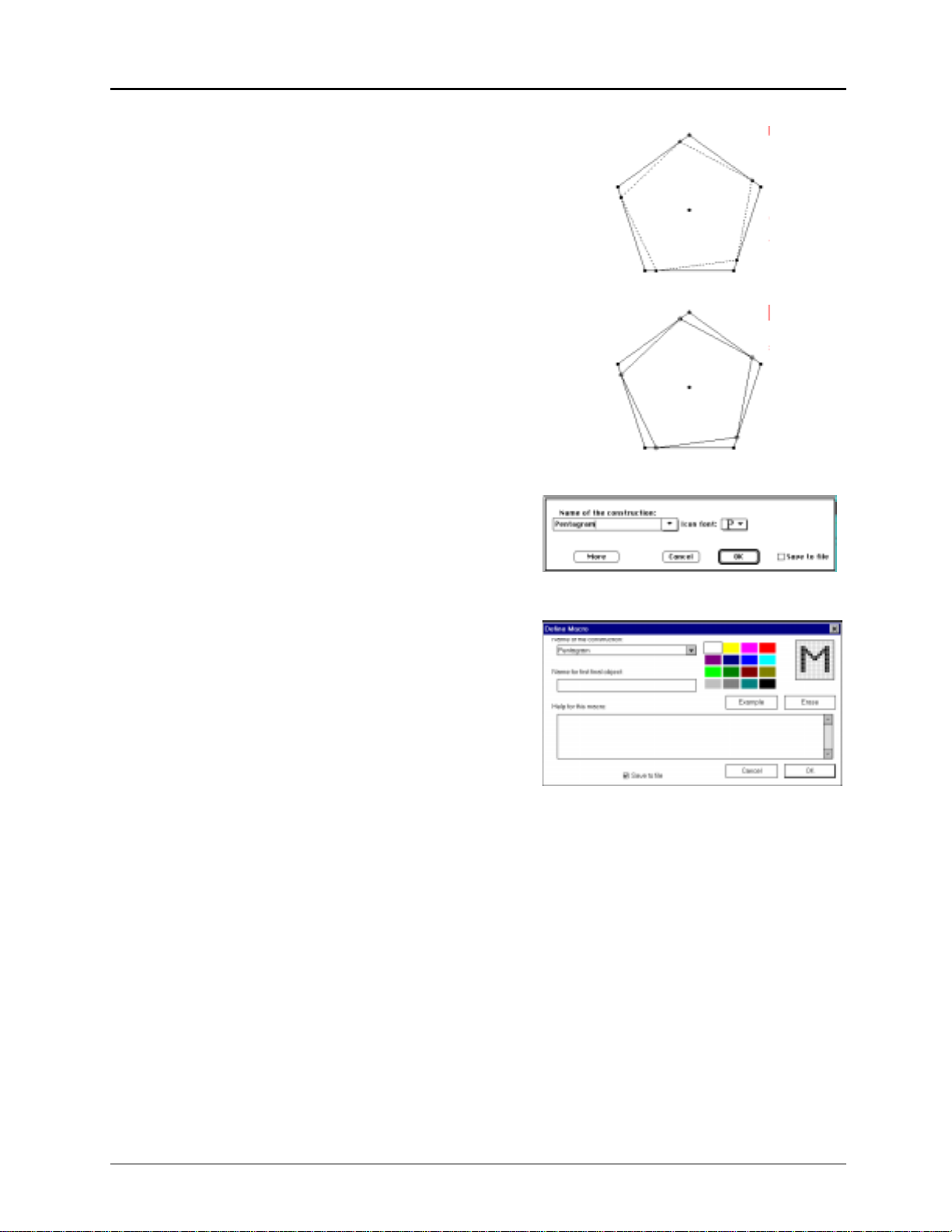
Inscribe the regular pentagon
16. Select the
Use the
Segment Division
Polygon
Polygon
macro. Proceed in a clockwise direction. Do
tool from the
tool to connect the points created by the
not connect the vertices of the regular pentagon.
Select each point. When all of the points have been selected,
select the first point again. This terminates the polygon. An
inscribed regular pentagon is created.
Lines
toolbox (third button).
Define a macro to create an inscribed regular pentagon
17. Select
Initial Object
from the
regular pentagon as the initial object. Move the ! toward the
outer pentagon until the message
Click once. The pentagon is shown as a marquee outline.
Macro
toolbox. Select the outer
This regular polygon
appears.
Note: Objects created by macros can be used to generate
other macros. For example, the points created by the
Segment Division
macro now are being used in the definition
of the new macro.
Copying permitted provided TI copyright notice is included
© 1997, 1999 Texas Instruments Incorporated
Getting Started with Cabri Geometry II 35
Page 38
Constructing a Macro: Pentagonal Curve of Pursuit
(Continued)
18. Select
Final Object
from the
Macro
toolbox. Select the
inner pentagon as the final object. The macro is now
ready to be defined.
Note: A macro generates its final object with the
object’s existing attributes when
Define Macro
is chosen.
These attributes can be changed at any time prior to the
selection of
19. Select
Define Macro
Hide/Show
from the
.
Draw
toolbox (last button).
Select each vertex of the final object (the inner regular
pentagon).
These points will be hidden when the regular pentagon
is generated from the macro.
20. Select
Define Macro
from the
Macro
toolbox. A dialogue
box appears in which you name your macro.
21. Enter the name “Pentagram” from your keyboard in the
field labeled
Click on the
Name of the construction:
Save to file
box. This is the only opportunity
.
to save the macro to an independent file, although it will
automatically be saved with the construction.
Macintosh
Windows, DOS
22. You can enter a help message and the name of the first
final object for future reference. It is a good idea to
document how your macro works in these fields. Enter
appropriate messages.
OK
23. Click on the
now appears in the
Pentagram
button to save the macro. The macro
Macro
toolbox with the name
. The macro will generate an inscribed regular
polygon.
36
Getting Started with Cabri Geometry II
Note: Colors available in Windows
version only.
Copying permitted provided TI copyright notice is included
© 1997, 1999 Texas Instruments Incorporated
Page 39

Test the Pentagonal Curve of Pursuit macro
24. Select the
the inner regular pentagon until the message
appears. Click to create a new inscribed pentagon within the
selected pentagon.
Does the macro meet your criteria? If not, repeat the
definition of initial and final objects and selection of
attributes. If problems still exist, you may need to review
the original construction again.
Pentagram
macro from the
Macro
toolbox. Point to
This polygon
Continue to apply the Pentagram macro
25. Apply the macro
to the new inner pentagon and click to create yet another
pentagon. Repeat until you have a construction similar to
the illustration.
Note: As your construction gets more and more crowded,
you can rely on the ambiguity feature of Cabri II to select
the pentagon created last. That is, the * pointer may appear
along with the message
mouse to see a list of the objects available. Point to the last
object in the list, which is the last object created, and
release the mouse to select it. Your computer’s response will
become slower as more objects are added to the
construction.
Pentagram
to the construction again. Point
Which object?
Press and hold the
Optional macros
It is also possible to combine more steps in a macro. For
example, create four inscribed pentagons, select the original
pentagon as the initial object, select the remaining pentagons as
the final objects. The macro then will generate four inscribed
pentagons.
Other line designs
Try using this technique to construct other line designs.
This example was inspired by Dale Seymour’s book
Introduction to Line Designs published by Dale Seymour
Publications.
Copying permitted provided TI copyright notice is included
© 1997, 1999 Texas Instruments Incorporated
Getting Started with Cabri Geometry II 37
Page 40

Menu Options
File
Edit
Ctrl+N New
Ctrl+O Open...
Ctrl+S Save
Save as...
Revert...
Ctrl+P Show Drawing...
Page Setup...
(Macintosh, Windows)
Printer Setup...
Print...
Ctrl+Q Quit
Ctrl+Z Undo
(DOS)
Open a new Cabri Geometry II drawing.
Open a saved Cabri Geometry II drawing.
Save the current Cabri Geometry II drawing in the file from
which it was loaded.
Save the current Cabri Geometry II drawing to a specified file.
Replace the current drawing with the most recently saved
version.
Zoom out to the one-square meter drawing sheet; reposition the
window.
Select printer and page options.
Print the current page (Macintosh, Windows, DOS) or the entire
drawing area (Macintosh only).
Close Cabri Geometry II.
Undo the last action.
Ctrl+X Cut
Ctrl+C Copy
Ctrl+V Paste
Clear
Ctrl+A Select all
Replay Construction
Ctrl+F Refresh Drawing
Remove the selected object(s) from the drawing to the
clipboard.
Copy the selected object(s) from the drawing to the clipboard.
Paste the clipboard contents into the current drawing.
Clear (erase, delete) all selected items.
Select all objects in the drawing.
Replays each step of a construction.
Refresh the drawing screen; remove leftover
Trace
elements.
38 Getting Started with Cabri Geometry II
Copying permitted provided TI copyright notice is included
© 1997, 1999 Texas Instruments Incorporated
Page 41

Options
Hide/Show Attributes
Preferences...
Tool Configuration...
Help
A
Help
About...
Helpful Shortcuts
Press + or
(Macintosh)
(Windows, DOS)
-
Press Shift
Press Tab
Hide the toolbar or display the toolbar that controls how
objects look.
Set preferences for how drawings are set up.
Rearrange or hide tools.
Displays a description of the selected toolbar icon in the Help
window at the bottom of the Cabri Geometry II screen.
Displays information about Cabri Geometry II that includes the
authors’ names, copyright notice, and the version number of the
software.
¦ To increase or decrease the displayed precision in
Edit
.
¦ To increase or decrease the animation speed in
Multiple Animation
.
Numerical
Animation
or
¦ To increase or decrease the number of objects in the
selected locus.
¦ To limit the slope of lines, rays, segments, vectors, triangles,
polygons, or axes to increments of 15º.
¦ To limit the radius to multiples of 1 cm when creating
circles.
¦ To select multiple objects.
¦ To record new values in a table.
¦ To change the format of a selected equation.
Press Enter
Press and hold the mouse key
To start a Multiple Animation.
To display all directly moveable (basic and independent)
objects as flashing. The cursor must be in an unoccupied space.
Press Ctrl and drag the mouse
Double-click the mouse key
To scroll the drawing window.
On a label, comment, numerical value, or table to invoke the
appropriate editor.
Click the mouse key
Anywhere in the gray area of the Toolbar to access the
tool.
Ctrl+U
Displays list of units in a pop-up menu when the Numerical Edit
tool is selected.
Copying permitted provided TI copyright notice is included
© 1997, 1999 Texas Instruments Incorporated
Pointer
Getting Started with Cabri Geometry II 39
Page 42

Toolbar Commands
Pointer
Points
Lines
Pointer
Rotate
Dilate
Rotate and Dilate
Point
Point on Object
Intersection Point(s)
Line
Segment
Ray
Vector
Select, move, and manipulate objects.
Rotate an object around a selected point or the object’s geometric
center.
Expand or contract an object around a selected point or the
object’s geometric center.
Simultaneously rotate and dilate an object around a selected point
or the object’s geometric center.
Construct a point defined in free space, on an object, or at the
intersection of two objects.
Construct a point defined on an object.
Construct a point at each intersection of two selected objects.
Construct an infinite line through a point at a slope (specified by
clicking a second time in free space or at a point).
Construct a segment, defined by two end points, which may be
created or defined in free space or on a defined object.
Construct a ray, defined by an end point and direction, extending
infinitely.
Construct a vector with magnitude and direction defined by two
points.
Triangle
Polygon
Regular Polygon
Construct a triangle, defined by three points (vertices), which may
be created or defined in free space or on a defined object.
Construct an n-sided polygon; the last point must coincide with the
beginning point. Select or create a point for each vertex.
Construct an n-sided regular polygon. Click for center and radius,
move clockwise (convex) or counterclockwise (star) to set n (30).
Curves
Circle
Arc
Conic
40 Getting Started with Cabri Geometry II
Construct a circle defined by a center point and a specified radius.
Construct an arc defined by an initial end point, a radius point, and
a final end point.
Construct a conic (ellipse, parabola, or hyperbola) defined by five
points.
Copying permitted provided TI copyright notice is included
© 1997, 1999 Texas Instruments Incorporated
Page 43

Construct
Perpendicular Line
Parallel Line
Midpoint
Perpendicular Bisector
Angle Bisector
Vector Sum
Compass
Measurement Transfer
Locus
Redefine Point
(Macintosh, DOS)
Construct a line perpendicular to a selected line, segment, ray,
vector, axis, or side of a polygon, passing through a created or
selected point.
Construct a line parallel to a selected line, segment, ray, vector,
axis, or side of a polygon, passing through a created or selected
point.
Construct a midpoint of two selected points, a segment, or side
of a polygon.
Construct a perpendicular line bisecting two points, a segment,
or side of a polygon.
Construct a line that bisects an angle identified by three
selected points; the second point is the vertex.
Construct the sum of two vectors by specifying the vectors and
the end point of the new vector.
Construct a circle from a center point with radius defined by a
segment or the distance between two selected points.
Create points on specific objects based on proportional or
equivalent selected numerical values.
Construct the locus of a single selected point or object defined
by movement along a path.
Redefine a previously defined point to a new location. (Defining
a point in free space as on an object, for example.)
Transform
Redefine Object
(Windows)
Reflection
Symmetry
Translation
Rotation
Dilation
Inverse
Redefines a previously defined point, object, or line.
Create the image of an object reflected across a line, segment,
ray, vector, axis, or side of a polygon.
Create the image of an object rotated 180¡ around a point .
Create the image of an object translated by a specified vector.
Create the image of an object rotated around a point by a
specified angular value.
Create the image of an object dilated from a point by a specified
factor.
Create the image of a point by reflecting it inversely to the
radius of a selected circle.
Copying permitted provided TI copyright notice is included
© 1997, 1999 Texas Instruments Incorporated
Getting Started with Cabri Geometry II 41
Page 44

Toolbar Commands
Macro
(Continued)
Check Property
Measure
Initial Object
Final Object
Define Macro
Collinear
Parallel
Perpendicular
Equidistant
Member
Specify the initial object(s) needed to define the final object(s).
Specify the final object(s) that will result from the initial
object(s).
Open the dialogue box for naming and saving the macro defined
by the initial and final object(s). The macro is added to the
Macro
toolbox.
Report whether or not three selected points are on the same
line.
Report whether or not two selected lines, segments, rays,
vectors, axes, or sides of a polygon are parallel.
Report whether or not two selected lines, segments, rays,
vectors, axes, or sides of a polygon are perpendicular.
Report whether or not three selected points are equidistant.
Report whether or not a selected point lies on a selected object.
Distance & Length
Area
Slope
Angle
Equation & Coordinates
Calculate
Tabulate
Display the distance between two selected points or the length
of a segment, perimeter, circumference, or radius.
Display the area of a selected polygon, circle, or ellipse.
Display the slope of a selected line, segment, ray, or vector.
Display the measure of a marked angle or an angle defined by
three selected points.
Display the coordinates of a point or the equation of a line,
circle, or conic.
Open the calculator to perform calculations using
measurements, numerical values, calculation results, or
numerical inputs from the keyboard.
Collect selected measurements, calculations, numerical values,
or coordinates of a point into a single data table.
42 Getting Started with Cabri Geometry II
Copying permitted provided TI copyright notice is included
© 1997, 1999 Texas Instruments Incorporated
Page 45

Display
Draw
Label
Comments
Numerical Edit
Mark Angle
Fix/Free
Trace On/Off
Animation
Multiple Animation
Hide/
Show
Attach a user-created label to a point, line, or circle. The label
may contain text and numbers.
Enter a comment in the drawing. The comment window is
defined by location and size.
Edit any measurement, coordinate, or equation; the value,
precision, units, font, size, and style may be modified.
Place an angle mark on an angle defined by three points, the
second of which is the vertex.
Fix the location of a point.
Free a fixed point.
Trace a selected object along a specified path.
Quit tracing.
Automatically translate, rotate, or dilate an object in the
direction specified by the animation spring. Click once to stop
the animation.
Animate multiple objects along multiple paths.
Select objects to hide (including labels and measurements).
Show hidden objects.
Color
Fill
Thick
Dotted
Modify Appearance
Show Axes
Hide Axes
New Axes
Define Grid
Open a color palette for changing the color of a selected object.
Fill a triangle, polygon, or circle with a selected color.
Change the appearance of an object by selecting a thick line.
Change the appearance of an object by selecting a dotted line.
Open an attribute palette for changing the appearance of
objects.
Show the default coordinate system for coordinate geometry.
Hide the default coordinate system.
Create a coordinate system by defining a point for the origin, a
point for the x-axis, and a point for the y-axis.
Display a grid for the selected axes.
Copying permitted provided TI copyright notice is included
© 1997, 1999 Texas Instruments Incorporated
Getting Started with Cabri Geometry II 43
Page 46
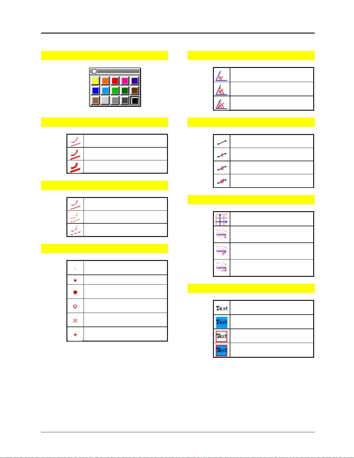
Toolbar Commands
(Continued)
Color Palette
Line Thickness
Light lines
Medium lines
Thick lines
Line Appearance
Solid lines
Dotted lines
Angle Mark
1 tick mark
2 tick marks
3 tick marks
Segment Mark
No tick mark
1 tick mark
2 tick marks
3 tick marks
Cartesian & Polar Coordinates
Cartesian coordinates
Point Types
Dashed lines
Small point
Medium point
Large point
Hollow point
Crosspoint
Cross
Polar coordinates measured in
degrees
Polar coordinates measured in
grads
Polar coordinates measured in
radians
Text Appearance
Plain
Colored background
In box
In colored box
44 Getting Started with Cabri Geometry II
Copying permitted provided TI copyright notice is included
© 1997, 1999 Texas Instruments Incorporated
 Loading...