

Product
Folder
Order
Now
Technical
Documents
Tools &
Software
Support &
Community
AFE76xx Quad/dual-channel, RF sampling analog front-end
with 14-bit 9GSPS DACs and 14-bit 3GSPS ADCs
1 Device Overview
1.1 Features
1
• 14-Bit resolution
• Sample rate:
– DAC: 9GSPS
– ADC: 3GSPS
• RF Frequency range: up to 5.2 GHz
• Maximum RF signal bandwidth
– Quad-channel mode (4T4R): 800 MHz (single-
band); 300 MHz (dual-band)
– Dual-channel mode (2T2R): 1200 MHz
(TX)/1000 MHz (RX) (single-band);
800MHz(dual-band)
• On-chip dual selectable DSAs per RX channel
• Integrated TX DSA functionality
• Digital:
– Dual band digital up-converters (DUCs)
– Dual Band digital down-converters (DDCs)
AFE7681, AFE7683, AFE7684, AFE7685, AFE7686
SLASEQ7E –MAY 2018–REVISED MARCH 2019
– 32-Bit NCOs for DUCs/DDCs
– Interpolation ratio: 6x, 8x, 9x, 12x, 16x, 18x,
24x, 36x
– Decimation ratio: /2, /3, /4, /6, /8, /9, /12, /16,
/18, /24, /32
– RX/FB Dynamic switching for TDD
• Interface:
– 8 SerDes Transceivers up to 15Gbps
– 16-Bit and 12-bit JESD204B transport layer
formatting with 8b/10b encoding
– Subclass 1 multi-device synchronization
• Clock:
– Internal PLL/VCO to generate DAC and ADC
clocks
• Package: 17mm x 17mm FC BGA, 0.8mm pitch
• Power supplies: 1.85 V, 1.15 V, 1.0 V, –1.8 V
1.2 Applications
• Cellular base stations
• Wideband communications
• Microwave backhaul
• Distributed antenna systems (DAS)
1.3 Description
The AFE76xx is a family of high performance, quad/dual channel, 14-bit, integrated RF sampling analog
front ends (AFEs) with 9 GSPS DACs and 3 GSPS ADCs, capable of synthesizing and digitizing wideband
signals. High dynamic range allows the AFE76xx to generate and digitize 3G/4G signals for wireless base
stations. In TDD mode, the receiver channel can be configured to dynamically switching between traffic
receiver (TDD RX) status and wideband feedback receiver (TDD FB) status to assist DPD (Digital PreDistortion) of the Power Amplifier (PA) on the transmitter path.
The AFE76xx family has integrated DSA on the receiver channels and also supports DSA equivalent
functionality on the transmitter channels. Each receiver channel has one analog RF peak power detector
and various digital power detectors to assist AGC control for receiver channels, and two RF overload
detectors for device reliability protection. The AFE76xx family has 8 of JESD204B compatible SerDes
transceivers running up to 15 Gbps. The devices have up to two DUCs per TX channel and two DDCs per
RX channel, with multiple interpolation/decimation rates and digital quadrature modulators/demodulators
with independent, frequency flexible NCOs. The devices support more than 1000 MHz (800 MHz as
4T4R) RF signal bandwidth in single-band mode, and up to 800 MHz (300 MHz as 4T4R) RF signal
bandwidth per band in dual-band mode. A low jitter PLL/VCO simplifies the sampling clock generation by
allowing use of a lower frequency reference clock.
Device Information
PART NUMBER PACKAGE BODY SIZE
AFE7685 FC-BGA 17.00 mm x 17.00 mm
AFE7686 FC-BGA 17.00 mm x 17.00 mm
(1)
(1) For all available packages, see the orderable addendum at the end of the data sheet.
1
An IMPORTANT NOTICE at the end of this data sheet addresses availability, warranty, changes, use in safety-critical applications,
intellectual property matters and other important disclaimers. PRODUCTION DATA.
RXBDSA1P/M
RXBDSA2P/M
Buffer
SHA
RXADSA1P/M
ADC
DSA
DSA
RXADSA2P/M
ADC
Buffer
SHA
ADC
DSA
DSA
ADC
NCO NCO
DDC
DDC
NCO NCO
TXCP/M
NCO
TXBP/M
DAC
DAC
NCO
DUC
DUC
NCO NCO
ADC
DSA
DSA
DSA
DSA
NCO NCO
DDC
DDC
NCO NCO
Buffer SHA
Buffer SHA
ADC
RXDDSA1P/M
RXDDSA2P/M
RXCDSA1P/M
RXCDSA2P/M
NCO NCO
DUC
DUC
NCO NCO
DAC
DAC
Low jitter PLL
Divider
/2, /3, /4
SerDes
Traffic Controller
TXDP/M
TXAP/M
SYSREFP/M
CLKP/M
JTAG
SRX1P/M
STX4P/M
SYNCBOUT0P/M
SYNCBINP/M
STX1P/M
SRX4P/M
STX8P/M
STX5P/M
SYNCBIN1P/M
SYNCBOUT1P/M
SRX5P/M
SRX8P/M
TXD DSA
TXC DSA
TXB DSA
TXA DSA
SPIBSEN
SPIBSCLK
SPIBSDIO
SPIBSDO
TXTDD2
RXTDD2
RXFBSW2
FBBANDSEL2
RXCDSA1PD
RXCDSA2PD
RXDDSA1PD
RXDDSA2PD
RXCPD2H
RXCPD2L
RXDPD2H
RXDPD2L
RXCDSAFAST
RXDDSAFAST
TX2ENABLE
ALARMTX2
SLEEPMODE
PLLCLKLD
PLLREFLD
RESET
TX1ENABLE
RXBDSAFAST
RXADSAFAST
RXBPD2L
RXBPD2H
RXAPD2L
RXAPD2H
RXBDSA2PD
RXBDSA1PD
RXADSA2PD
RXADSA1PD
FBBANDSEL1
RXFBSW1
RXTDD1
TXTDD1
SPIASDO
SPIASDIO
SPIASCLK
SPIASEN
ALARMTX1
TCLK
TCLK
TDI
TDO
TRSTB
Temp Sensor
VDDAPLL18
VDDAVCO18
VDDAPLL
VDDCLK
VDDATX18
VDDATX
VDDCLK
VDDGPIO18
VEE18AB
VDDL1AB
VDDL2AB
VDDTX18CD
VDDTXCD
VEE18CD
VDDL2CD
VDDL1CD
FSPICLKD
FSPIDD
DVDD
VDDTX18AB
VDDTXAB
DVDD
DVDD
VDDT
VDDR
VDDA
DVDD
RX1P8V
RX1P2V
SYNCB2CMOS
SYNCB3CMOS
SYNCB1CMOS
SYNCB0CMOS
RXDSASW
TXDSASW
FSPICLKA
FSPIDA
FSPICLKB
FSPIDB
FSPICLKC
FSPIDC
RX1P8V
RX1P2V
DVDD
CLKOUTP/M
MUX MUX
MUX
MUX
AFE7681, AFE7683, AFE7684, AFE7685, AFE7686
SLASEQ7E –MAY 2018–REVISED MARCH 2019
www.ti.com
Device Information
(1)
(continued)
PART NUMBER PACKAGE BODY SIZE
AFE7684 FC-BGA 17.00 mm x 17.00 mm
AFE7683 FC-BGA 17.00 mm x 17.00 mm
AFE7681 FC-BGA 17.00 mm x 17.00 mm
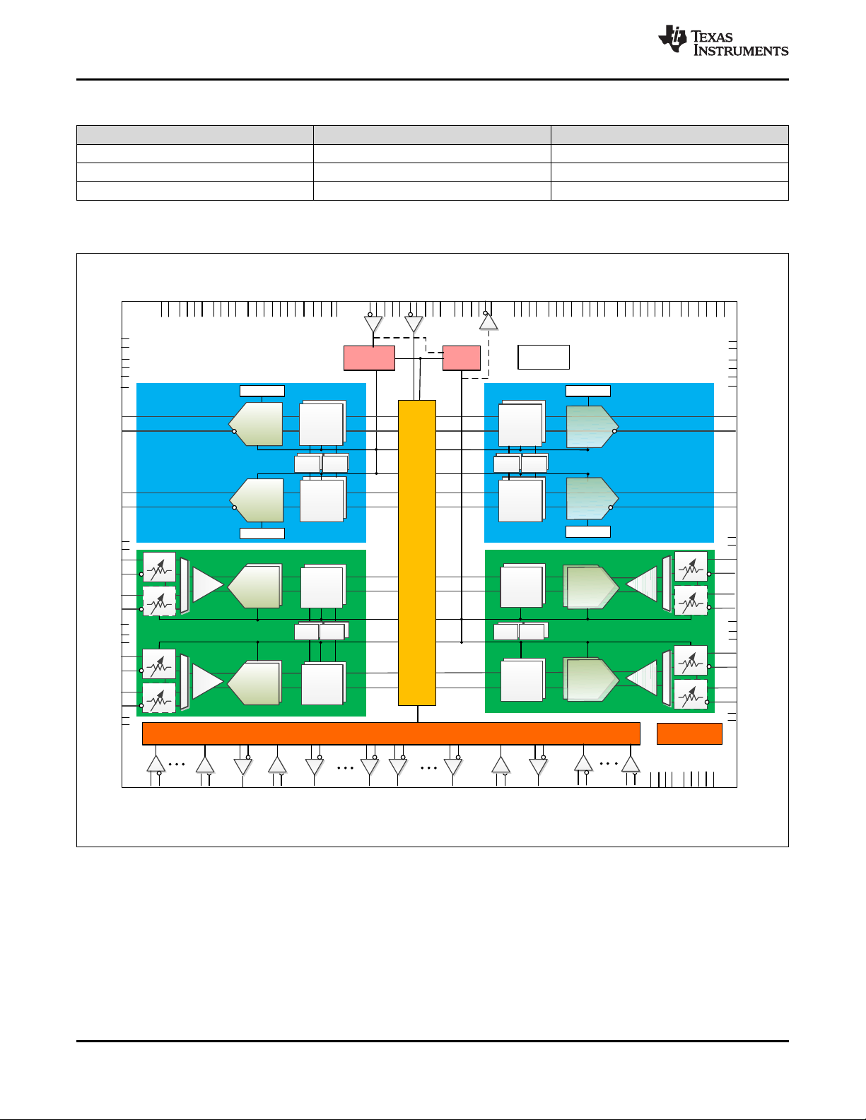
1.4 Functional Block Diagram
Figure 1-1. Functional Block Diagram of AFE7685/AFE7686
2
Device Overview Copyright © 2018–2019, Texas Instruments Incorporated
Submit Documentation Feedback
Product Folder Links: AFE7681 AFE7683 AFE7684 AFE7685 AFE7686
RXBDSA1P/M
RXBDSA2P/M
Buffer
SHA
RXADSA1P/M
ADC
DSA
DSA
RXADSA2P/M
ADC
Buffer
SHA
ADC
DSA
DSA
ADC
NCO NCO
DDC
DDC
NCO NCO
TXCP/M
NCO
DAC
NCO
DUC
NCO NCO
ADC
DSA
DSA
DSA
DSA
NCO NCO
DDC
DDC
NCO NCO
Buffer SHA
Buffer SHA
ADC
RXDDSA1P/M
RXDDSA2P/M
RXCDSA1P/M
RXCDSA2P/M
NCO NCO
DUC
NCO NCO
DAC
Low jitter PLL
Divider
/2, /3, /4
SerDes
Traffic Controller
TXAP/M
SYSREFP/M
CLKP/M
JTAG
SRX1P/M
STX4P/M
SYNCBOUT0P/M
SYNCBINP/M
STX1P/M
SRX4P/M
STX8P/M
STX5P/M
SYNCBIN1P/M
SYNCBOUT1P/M
SRX5P/M
SRX8P/M
TXC DSA
TXA DSA
SPIBSEN
SPIBSCLK
SPIBSDIO
SPIBSDO
TXTDD2
RXTDD2
RXFBSW2
FBBANDSEL2
RXCDSA1PD
RXCDSA2PD
RXDDSA1PD
RXDDSA2PD
RXCPD2H
RXCPD2L
RXDPD2H
RXDPD2L
RXCDSAFAST
RXDDSAFAST
TX2ENABLE
ALARMTX2
SLEEPMODE
PLLCLKLD
PLLREFLD
RESET
TX1ENABLE
RXBDSAFAST
RXADSAFAST
RXBPD2L
RXBPD2H
RXAPD2L
RXAPD2H
RXBDSA2PD
RXBDSA1PD
RXADSA2PD
RXADSA1PD
FBBANDSEL1
RXFBSW1
RXTDD1
TXTDD1
SPIASDO
SPIASDIO
SPIASCLK
SPIASEN
ALARMTX1
TCLK
TCLK
TDI
TDO
TRSTB
Temp Sensor
VDDAPLL18
VDDAVCO18
VDDAPLL
VDDCLK
VDDATX18
VDDATX
VDDCLK
VDDGPIO18
VEE18AB
VDDL1AB
VDDL2AB
VDDTX18CD
VDDTXCD
VEE18CD
VDDL2CD
VDDL1CD
FSPICLKD
FSPIDD
DVDD
VDDTX18AB
VDDTXAB
DVDD
DVDD
VDDT
VDDR
VDDA
DVDD
RX1P8V
RX1P2V
SYNCB2CMOS
SYNCB3CMOS
SYNCB1CMOS
SYNCB0CMOS
RXDSASW
TXDSASW
FSPICLKA
FSPIDA
FSPICLKB
FSPIDB
FSPICLKC
FSPIDC
RX1P8V
RX1P2V
DVDD
CLKOUTP/M
MUX MUX
MUX
MUX
www.ti.com
AFE7681, AFE7683, AFE7684, AFE7685, AFE7686
SLASEQ7E –MAY 2018–REVISED MARCH 2019
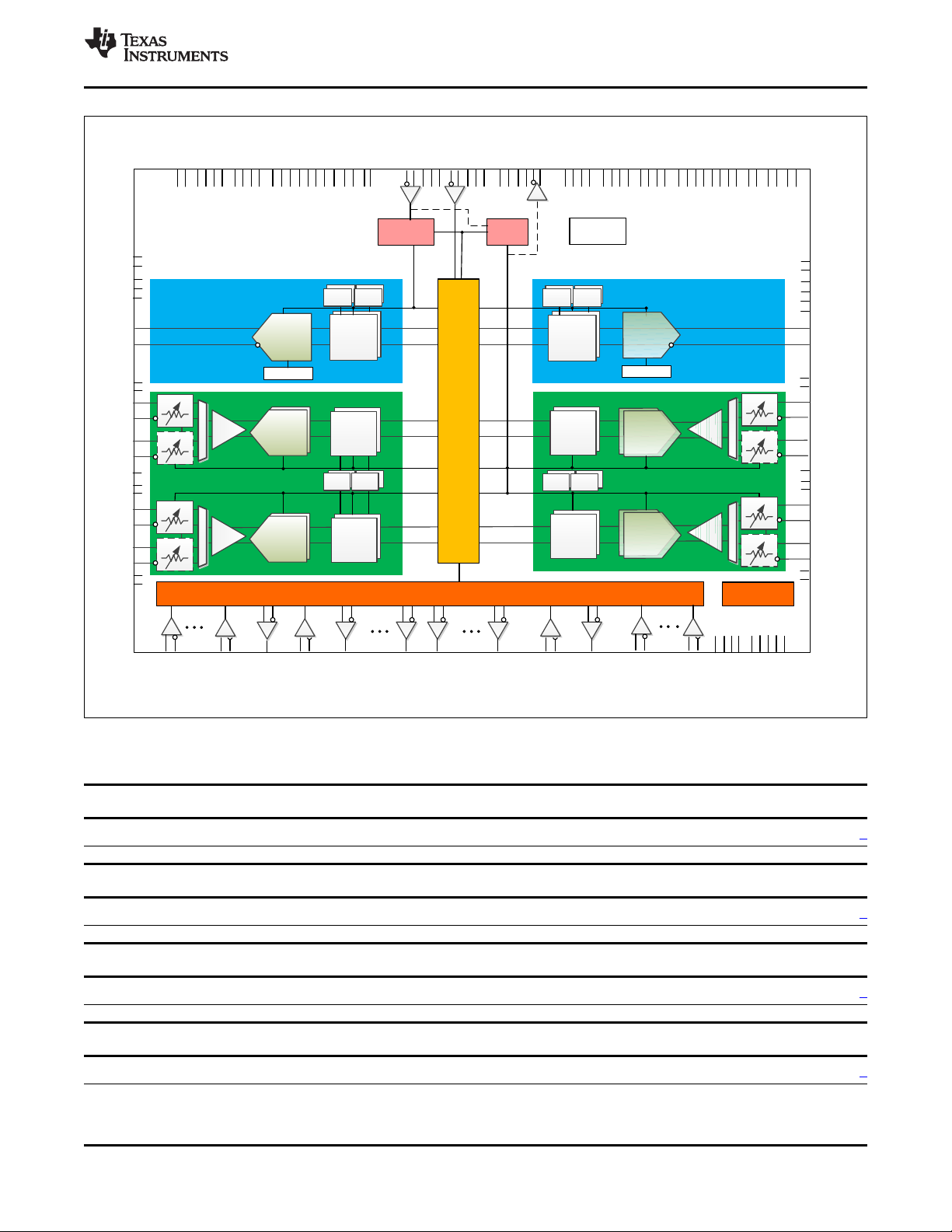
Figure 1-2. Functional Block Diagram of AFE7684
2 Revision History
Changes from Revision D (December 2018) to Revision E Page
• Changed AFE7681 from Advance Information to Production Data ............................................................ 1
Changes from Revision C (October 2018) to Revision D Page
• Added AFE7681 as Advance Information and AFE7683 as Production Data................................................ 1
Changes from Revision B (September 2018) to Revision C Page
• Changed AFE7684 from Advance Information to Production Data ............................................................ 1
Changes from Revision A (July 2018) to Revision B Page
• Changed AFE7686 from Advance Information to Production Data ............................................................ 1
Revision HistoryCopyright © 2018–2019, Texas Instruments Incorporated
Submit Documentation Feedback
Product Folder Links: AFE7681 AFE7683 AFE7684 AFE7685 AFE7686
3

AFE7681, AFE7683, AFE7684, AFE7685, AFE7686
SLASEQ7E –MAY 2018–REVISED MARCH 2019
Changes from Original (May 2018) to Revision A Page
• Changed AFE7684 from Product Preview to Advance Information, AFE7685 from Product Preview to Production
Data..................................................................................................................................... 1
• Deleted AFE7683 from data manual .............................................................................................. 1
www.ti.com
4
Revision History Copyright © 2018–2019, Texas Instruments Incorporated
Submit Documentation Feedback
Product Folder Links: AFE7681 AFE7683 AFE7684 AFE7685 AFE7686
www.ti.com
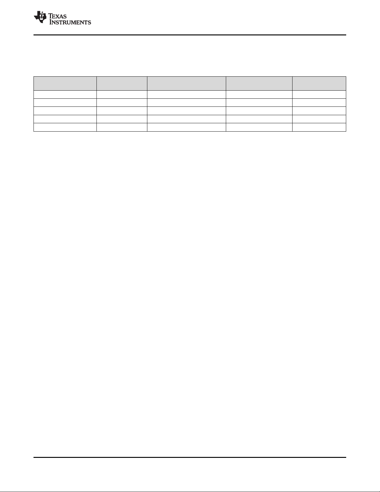
3 Device Comparison
AFE7681, AFE7683, AFE7684, AFE7685, AFE7686
SLASEQ7E –MAY 2018–REVISED MARCH 2019
Table 3-1. Device Features Comparison
DEVICE # of TXs/RXs # of DUCs/TX # of DDCs/RX
AFE7685 4T4R 1 1 750
AFE7686 4T4R 2 2 1500
AFE7684 2T4R 2 2 1500
AFE7683 2T4R 1 1 750
AFE7681 4T2R 1 1 750
MAX INPUT/OUTPUT
DATA RATE (MSPS)
Submit Documentation Feedback
Product Folder Links: AFE7681 AFE7683 AFE7684 AFE7685 AFE7686
Device ComparisonCopyright © 2018–2019, Texas Instruments Incorporated
5

AFE7681, AFE7683, AFE7684, AFE7685, AFE7686
SLASEQ7E –MAY 2018–REVISED MARCH 2019
4 Device and Documentation Support
4.1 Device Support
4.1.1 Third-Party Products Disclaimer
TI'S PUBLICATION OF INFORMATION REGARDING THIRD-PARTY PRODUCTS OR SERVICES DOES
NOT CONSTITUTE AN ENDORSEMENT REGARDING THE SUITABILITY OF SUCH PRODUCTS OR
SERVICES OR A WARRANTY, REPRESENTATION OR ENDORSEMENT OF SUCH PRODUCTS OR
SERVICES, EITHER ALONE OR IN COMBINATION WITH ANY TI PRODUCT OR SERVICE.
4.2 Documentation Support
To receive notification of documentation updates, navigate to the device product folder on ti.com. In the
upper right corner, click on Alert me to register and receive a weekly digest of any product information that
has changed. For change details, review the revision history included in any revised document.
The current documentation that describes the DSP, related peripherals, and other technical collateral is
listed below.
4.2.1 Related Documentation
AFE76xx EVM Design Document User's Guide (SLAU761)
www.ti.com
AFE76xx Technical Reference Manual (SLAU744)
AFE76xx Programmer's User's Guide (SLAU767)
4.3 Related Links
The table below lists quick access links. Categories include technical documents, support and community
resources, tools and software, and quick access to sample or buy.
Table 4-1. Related Links
PARTS PRODUCT FOLDER SAMPLE & BUY
AFE7681 Click here Click here Click here Click here Click here
AFE7683 Click here Click here Click here Click here Click here
AFE7684 Click here Click here Click here Click here Click here
AFE7685 Click here Click here Click here Click here Click here
AFE7686 Click here Click here Click here Click here Click here
TECHNICAL
DOCUMENTS
TOOLS &
SOFTWARE
4.4 Community Resources
The following links connect to TI community resources. Linked contents are provided "AS IS" by the
respective contributors. They do not constitute TI specifications and do not necessarily reflect TI's views;
see TI's Terms of Use.
TI E2E™ Online Community The TI engineer-to-engineer (E2E) community was created to foster
collaboration among engineers. At e2e.ti.com, you can ask questions, share knowledge,
explore ideas and help solve problems with fellow engineers.
TI Embedded Processors Wiki Established to help developers get started with Embedded Processors
from Texas Instruments and to foster innovation and growth of general knowledge about the
hardware and software surrounding these devices.
SUPPORT &
COMMUNITY
4.5 Trademarks
E2E is a trademark of Texas Instruments.
All other trademarks are the property of their respective owners.
6
Device and Documentation Support Copyright © 2018–2019, Texas Instruments Incorporated
Submit Documentation Feedback
Product Folder Links: AFE7681 AFE7683 AFE7684 AFE7685 AFE7686

www.ti.com
4.6 Electrostatic Discharge Caution
This integrated circuit can be damaged by ESD. Texas Instruments recommends that all integrated circuits be handled with
appropriate precautions. Failure to observe proper handling and installation procedures can cause damage.
ESD damage can range from subtle performance degradation to complete device failure. Precision integrated circuits may be more
susceptible to damage because very small parametric changes could cause the device not to meet its published specifications.
4.7 Export Control Notice
Recipient agrees to not knowingly export or re-export, directly or indirectly, any product or technical data
(as defined by the U.S., EU, and other Export Administration Regulations) including software, or any
controlled product restricted by other applicable national regulations, received from disclosing party under
nondisclosure obligations (if any), or any direct product of such technology, to any destination to which
such export or re-export is restricted or prohibited by U.S. or other applicable laws, without obtaining prior
authorization from U.S. Department of Commerce and other competent Government authorities to the
extent required by those laws.
4.8 Glossary
TI Glossary This glossary lists and explains terms, acronyms, and definitions.
AFE7681, AFE7683, AFE7684, AFE7685, AFE7686
SLASEQ7E –MAY 2018–REVISED MARCH 2019
Device and Documentation SupportCopyright © 2018–2019, Texas Instruments Incorporated
Submit Documentation Feedback
Product Folder Links: AFE7681 AFE7683 AFE7684 AFE7685 AFE7686
7

AFE7681, AFE7683, AFE7684, AFE7685, AFE7686
SLASEQ7E –MAY 2018–REVISED MARCH 2019
5 Mechanical, Packaging, and Orderable Information
5.1 Packaging Information
The following pages include mechanical, packaging, and orderable information. This information is the
most current data available for the designated devices. This data is subject to change without notice and
revision of this document. For browser-based versions of this data sheet, refer to the left-hand navigation.
www.ti.com
8
Mechanical, Packaging, and Orderable Information Copyright © 2018–2019, Texas Instruments Incorporated
Submit Documentation Feedback
Product Folder Links: AFE7681 AFE7683 AFE7684 AFE7685 AFE7686

PACKAGE OPTION ADDENDUM
www.ti.com
10-Dec-2020
PACKAGING INFORMATION
Orderable Device Status
AFE7681IABJ ACTIVE FCBGA ABJ 400 90 RoHS & Green SNAGCU Level-3-260C-168 HR -40 to 85 AFE7681I
AFE7683IABJ ACTIVE FCBGA ABJ 400 90 RoHS & Green SNAGCU Level-3-260C-168 HR -40 to 85 AFE7683I
AFE7684IABJ ACTIVE FCBGA ABJ 400 90 RoHS & Green SNAGCU Level-3-260C-168 HR -40 to 85 AFE7684I
AFE7685IABJ ACTIVE FCBGA ABJ 400 90 RoHS & Green SNAGCU Level-3-260C-168 HR -40 to 85 AFE7685I
AFE7686IABJ ACTIVE FCBGA ABJ 400 90 RoHS & Green SNAGCU Level-3-260C-168 HR -40 to 85 AFE7686I
(1)
The marketing status values are defined as follows:
ACTIVE: Product device recommended for new designs.
LIFEBUY: TI has announced that the device will be discontinued, and a lifetime-buy period is in effect.
NRND: Not recommended for new designs. Device is in production to support existing customers, but TI does not recommend using this part in a new design.
PREVIEW: Device has been announced but is not in production. Samples may or may not be available.
OBSOLETE: TI has discontinued the production of the device.
Package Type Package
(1)
Drawing
Pins Package
Qty
Eco Plan
(2)
Lead finish/
Ball material
(6)
MSL Peak Temp
(3)
Op Temp (°C) Device Marking
(4/5)
(2)
RoHS: TI defines "RoHS" to mean semiconductor products that are compliant with the current EU RoHS requirements for all 10 RoHS substances, including the requirement that RoHS substance
do not exceed 0.1% by weight in homogeneous materials. Where designed to be soldered at high temperatures, "RoHS" products are suitable for use in specified lead-free processes. TI may
reference these types of products as "Pb-Free".
RoHS Exempt: TI defines "RoHS Exempt" to mean products that contain lead but are compliant with EU RoHS pursuant to a specific EU RoHS exemption.
Green: TI defines "Green" to mean the content of Chlorine (Cl) and Bromine (Br) based flame retardants meet JS709B low halogen requirements of <=1000ppm threshold. Antimony trioxide based
flame retardants must also meet the <=1000ppm threshold requirement.
(3)
MSL, Peak Temp. - The Moisture Sensitivity Level rating according to the JEDEC industry standard classifications, and peak solder temperature.
(4)
There may be additional marking, which relates to the logo, the lot trace code information, or the environmental category on the device.
(5)
Multiple Device Markings will be inside parentheses. Only one Device Marking contained in parentheses and separated by a "~" will appear on a device. If a line is indented then it is a continuation
of the previous line and the two combined represent the entire Device Marking for that device.
(6)
Lead finish/Ball material - Orderable Devices may have multiple material finish options. Finish options are separated by a vertical ruled line. Lead finish/Ball material values may wrap to two
lines if the finish value exceeds the maximum column width.
Samples
Addendum-Page 1

PACKAGE OPTION ADDENDUM
www.ti.com
Important Information and Disclaimer:The information provided on this page represents TI's knowledge and belief as of the date that it is provided. TI bases its knowledge and belief on information
provided by third parties, and makes no representation or warranty as to the accuracy of such information. Efforts are underway to better integrate information from third parties. TI has taken and
continues to take reasonable steps to provide representative and accurate information but may not have conducted destructive testing or chemical analysis on incoming materials and chemicals.
TI and TI suppliers consider certain information to be proprietary, and thus CAS numbers and other limited information may not be available for release.
10-Dec-2020
In no event shall TI's liability arising out of such information exceed the total purchase price of the TI part(s) at issue in this document sold by TI to Customer on an annual basis.
Addendum-Page 2

PACKAGE OUTLINE
BALL A1 CORNER
2.65 MAX
17.2
16.8
B
(2.08)
SCALE 0.750
17.2
16.8
FCBGA - 2.65 mm max heightABJ0400A
BALL GRID ARRAY
A
( 16)
0.2 C
C
SEATING PLANE
0.76
0.56
0.5
0.3
BALL TYP
TYP
NOTE 4
0.12 C
15.2 TYP
0.55
400X
0.45
0.15 C A B
0.08 C
NOTE 3
0.8 TYP
SYMM
Y
W
V
U
T
R
P
N
M
L
K
J
H
G
F
E
D
C
B
A
7
1
5
3
2
6
4
11
13
9
10
8
15 17
12
14
19
18
16
(0.9) TYP
SYMM
20
15.2
TYP
0.8 TYP
4221311/B 04/2020
NOTES:
1. All linear dimensions are in millimeters. Any dimensions in parenthesis are for reference only. Dimensioning and tolerancing
per ASME Y14.5M.
2. This drawing is subject to change without notice.
3. Dimension is measured at the maximum solder ball diameter, parallel to primary datum C.
4. Primary datum C and seating plane are defined by the spherical crowns of the solder balls.
www.ti.com

EXAMPLE BOARD LAYOUT
FCBGA - 2.65 mm max heightABJ0400A
BALL GRID ARRAY
(0.8) TYP
4
2
3
1
A
B
5
8
7
6
10
9
11
12
13
14
15
16
17
18
19
20
(0.8) TYP
400X
0.415
0.385
C
D
E
F
G
H
J
K
L
M
N
P
R
T
U
V
W
Y
SYMM
SYMM
LAND PATTERN EXAMPLE
EXPOSED METAL SHOWN
SCALE:6X
( 0.4)
METAL
SOLDER MASK
OPENING
NON-SOLDER MASK
DEFINED
(PREFERRED)
0.025 MAX
EXPOSED
METAL
0.025 MIN
EXPOSED
METAL
METAL
UNDER
MASK
SOLDER MASK
DEFINED
SOLDER MASK DETAILS
NOT TO SCALE
NOTES: (continued)
5. Final dimensions may vary due to manufacturing tolerance considerations and also routing constraints.
For more information, see Texas Instruments literature number SPRU811 (www.ti.com/lit/spru811).
www.ti.com
( 0.4)
SOLDER MASK
OPENING
4221311/B 04/2020

EXAMPLE STENCIL DESIGN
FCBGA - 2.65 mm max heightABJ0400A
BALL GRID ARRAY
(0.8)
TYP
(0.8) TYP
4
2
3
1
A
B
C
D
E
F
G
H
J
K
L
M
N
P
R
T
U
V
W
Y
7
6
5
8
9
( 0.4) TYP
10
11
12
13
14
15
16
17
18
19
20
SYMM
SYMM
SOLDER PASTE EXAMPLE
BASED ON 0.15 mm THICK STENCIL
SCALE:6X
NOTES: (continued)
6. Laser cutting apertures with trapezoidal walls and rounded corners may offer better paste release.
4221311/B 04/2020
www.ti.com

IMPORTANT NOTICE AND DISCLAIMER
TI PROVIDES TECHNICAL AND RELIABILITY DATA (INCLUDING DATASHEETS), DESIGN RESOURCES (INCLUDING REFERENCE
DESIGNS), APPLICATION OR OTHER DESIGN ADVICE, WEB TOOLS, SAFETY INFORMATION, AND OTHER RESOURCES “AS IS”
AND WITH ALL FAULTS, AND DISCLAIMS ALL WARRANTIES, EXPRESS AND IMPLIED, INCLUDING WITHOUT LIMITATION ANY
IMPLIED WARRANTIES OF MERCHANTABILITY, FITNESS FOR A PARTICULAR PURPOSE OR NON-INFRINGEMENT OF THIRD
PARTY INTELLECTUAL PROPERTY RIGHTS.
These resources are intended for skilled developers designing with TI products. You are solely responsible for (1) selecting the appropriate
TI products for your application, (2) designing, validating and testing your application, and (3) ensuring your application meets applicable
standards, and any other safety, security, or other requirements. These resources are subject to change without notice. TI grants you
permission to use these resources only for development of an application that uses the TI products described in the resource. Other
reproduction and display of these resources is prohibited. No license is granted to any other TI intellectual property right or to any third
party intellectual property right. TI disclaims responsibility for, and you will fully indemnify TI and its representatives against, any claims,
damages, costs, losses, and liabilities arising out of your use of these resources.
TI’s products are provided subject to TI’s Terms of Sale (www.ti.com/legal/termsofsale.html) or other applicable terms available either on
ti.com or provided in conjunction with such TI products. TI’s provision of these resources does not expand or otherwise alter TI’s applicable
warranties or warranty disclaimers for TI products.
Mailing Address: Texas Instruments, Post Office Box 655303, Dallas, Texas 75265
Copyright © 2020, Texas Instruments Incorporated
 Loading...