

Page 1
TSW1200
HP8644B
SynthesizedSignal
Generator
ClockSource
HP8644B
SynthesizedSignal
Generator
InputSource
LCFilter
LCFilter
10-MHzReferenceClock
ADS6149EVM
J
19
J6
J
7
5 V
J
15
J 7
6V
Quick Start Guide
SLAL176 – December 2008
ADS6149EVM
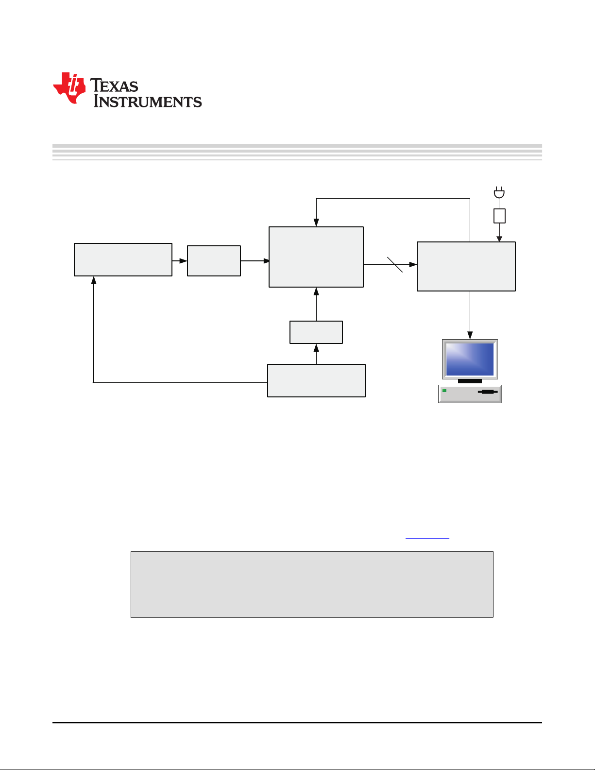
1 EVM Quick-Start Procedure
The ADS6149 EVM provides numerous options for providing clock, input frequency and power to the ADC
under evaluation. The quick start procedure describes how to quickly get initial results using the default
configuration of the EVM as it was shipped. The EVM can be put back to default configuration by setting
all jumpers the default values as described in Table 1 . The default configuration of the EVM is for the Input
Frequency (IF) and the clock input is for each to be a single ended input that is transformer-coupled to the
ADC. The default configuration for the power supply is to provide a single 5V supply to the red banana
jack J7, PWR_IN. The default configuration for the EVM is to control the modes of operation by jumper
settings for parallel input control pins rather than serial SPI control of the register space. The other modes
of operation of the EVM are described in the ADS6149 EVM Users Guide (SLWU061 )
CAUTION
Voltage Limits: Exceeding the maximum input voltages can damage EVM
components. Undervoltage can cause improper operation of some or all of the
EVM components.
A quick-setup procedure for the default configuration of the ADS6149EVM follows:.
1. Verify all jumper settings against the schematic jumper list in Table 1 .
SLAL176 – December 2008 ADS6149EVM 1
Submit Documentation Feedback
Page 2

EVM Quick-Start Procedure
www.ti.com
Table 1. Jumper List
Jumper Function Default Jumper Setting
Interface Circuit Operational Amplifier THS4509 (Bypassed)
SJP1 AMP_OUT+ 1-2
SJP2 AMP_OUT– 1-2
JP7 PD 1-2
SJP5 AMPIN- 1-2
ADC Circuit
JP12 Parallel 1-2
JP11 SDA open
JP9 SEN 1-2
JP15 OE open
J2 DFS open
J3 MODE 1-2
J1 SEN open
Clock Interface Circuit (Bypassed)
SJP4 CLOCKIN 1-2
SJP7 CLOCKIN, Y0, Y1P SELECT 1-2
SJP6 Y1N SELECT 1-2
J14 PWRDWN CDC 1-2
Power Supply
JP13 3.3VA_IN 1-2
JP14 3.3VD_IN 1-2
JP16 TPS79501 INPUT SELECT 1-2
JP19 5V_AUX 1-2
JP17 TPS5420 INPUT SELECT NO SHUNT
2. Connect the 5-V supply between J7 and J12 (GND). If you are using the TSW1200 for capture, it also
can be used to source 5 V for the EVM. On the TSW1200, configure JP8 to short 1-2, J22 to short 1-2,
and jumper over 5 V from the banana jacks on the TSW1200 to J7 on the ADC EVM. Do not connect a
voltage source greater than 5.5 V.
3. Switch on power supplies.
4. Using a function generator with 50- Ω output impedance, generate a 0-V offset, 1.5-Vpp sine-wave
clock into J19. The frequency of the clock must be within the specification for the device speed grade.
5. Use a frequency generator with a 50- Ω output impedance to provide a 0-V offset, –1-dBFS-amplitude
sine-wave signal into J6. This provides a transformer-coupled differential input signal to the ADC.
6. Connect the TSW1200 or suitable logic analyzer to J10 to capture the resulting digital data. If a
TSW1200 is being used to capture data, follow the additional alphabetically labeled steps.
a. After installing the TSW1200 software and connecting the TSW1200 to the USB port, open the
TSW1200 software.
b. Depending on the ADC under evaluation, select from the TI ADC Selection pulldown menu.
c. Change the ADC Sample Rate and ADC Input Frequency to match those of the signal generator.
d. After selecting a Single Tone FFT test, press the Capture Data button.
2 ADS6149EVM SLAL176 – December 2008
Submit Documentation Feedback
Page 3

IMPORTANT NOTICE
Texas Instruments Incorporated and its subsidiaries (TI) reserve the right to make corrections, modifications, enhancements, improvements,
and other changes to its products and services at any time and to discontinue any product or service without notice. Customers should
obtain the latest relevant information before placing orders and should verify that such information is current and complete. All products are
sold subject to TI’s terms and conditions of sale supplied at the time of order acknowledgment.
TI warrants performance of its hardware products to the specifications applicable at the time of sale in accordance with TI’s standard
warranty. Testing and other quality control techniques are used to the extent TI deems necessary to support this warranty. Except where
mandated by government requirements, testing of all parameters of each product is not necessarily performed.
TI assumes no liability for applications assistance or customer product design. Customers are responsible for their products and
applications using TI components. To minimize the risks associated with customer products and applications, customers should provide
adequate design and operating safeguards.
TI does not warrant or represent that any license, either express or implied, is granted under any TI patent right, copyright, mask work right,
or other TI intellectual property right relating to any combination, machine, or process in which TI products or services are used. Information
published by TI regarding third-party products or services does not constitute a license from TI to use such products or services or a
warranty or endorsement thereof. Use of such information may require a license from a third party under the patents or other intellectual
property of the third party, or a license from TI under the patents or other intellectual property of TI.
Reproduction of TI information in TI data books or data sheets is permissible only if reproduction is without alteration and is accompanied
by all associated warranties, conditions, limitations, and notices. Reproduction of this information with alteration is an unfair and deceptive
business practice. TI is not responsible or liable for such altered documentation. Information of third parties may be subject to additional
restrictions.
Resale of TI products or services with statements different from or beyond the parameters stated by TI for that product or service voids all
express and any implied warranties for the associated TI product or service and is an unfair and deceptive business practice. TI is not
responsible or liable for any such statements.
TI products are not authorized for use in safety-critical applications (such as life support) where a failure of the TI product would reasonably
be expected to cause severe personal injury or death, unless officers of the parties have executed an agreement specifically governing
such use. Buyers represent that they have all necessary expertise in the safety and regulatory ramifications of their applications, and
acknowledge and agree that they are solely responsible for all legal, regulatory and safety-related requirements concerning their products
and any use of TI products in such safety-critical applications, notwithstanding any applications-related information or support that may be
provided by TI. Further, Buyers must fully indemnify TI and its representatives against any damages arising out of the use of TI products in
such safety-critical applications.
TI products are neither designed nor intended for use in military/aerospace applications or environments unless the TI products are
specifically designated by TI as military-grade or "enhanced plastic." Only products designated by TI as military-grade meet military
specifications. Buyers acknowledge and agree that any such use of TI products which TI has not designated as military-grade is solely at
the Buyer's risk, and that they are solely responsible for compliance with all legal and regulatory requirements in connection with such use.
TI products are neither designed nor intended for use in automotive applications or environments unless the specific TI products are
designated by TI as compliant with ISO/TS 16949 requirements. Buyers acknowledge and agree that, if they use any non-designated
products in automotive applications, TI will not be responsible for any failure to meet such requirements.
Following are URLs where you can obtain information on other Texas Instruments products and application solutions:
Products Applications
Amplifiers amplifier.ti.com Audio www.ti.com/audio
Data Converters dataconverter.ti.com Automotive www.ti.com/automotive
DSP dsp.ti.com Broadband www.ti.com/broadband
Clocks and Timers www.ti.com/clocks Digital Control www.ti.com/digitalcontrol
Interface interface.ti.com Medical www.ti.com/medical
Logic logic.ti.com Military www.ti.com/military
Power Mgmt power.ti.com Optical Networking www.ti.com/opticalnetwork
Microcontrollers microcontroller.ti.com Security www.ti.com/security
RFID www.ti-rfid.com Telephony www.ti.com/telephony
RF/IF and ZigBee® Solutions www.ti.com/lprf Video & Imaging www.ti.com/video
Mailing Address: Texas Instruments, Post Office Box 655303, Dallas, Texas 75265
Copyright © 2008, Texas Instruments Incorporated
Wireless www.ti.com/wireless
 Loading...