

Page 1

DockMate
User’s Guide
Page 2

Copyright (©) 1995 Texas Instruments Incorporated
All Rights Reserved — Printed in U.S.A.
DockMate User’s Guide
TI Part No. 9794528-0001, Rev. A
Original Issue: August 1995
Changes may be made periodically to the information in
this publication. Such changes will be incorporated in new
editions of this manual.
No part of this publication may be reproduced, stored in a
retrieval system, or transmitted, in any form or by any
means, electronic, mechanical, photocopy, recording, or
otherwise, without the prior written permission of Texas
Instruments Incorporated.
TravelMate and DockMate are trademarks of Texas Instruments.
The icons in the Windows Notebook and Startup groups are copyrighted by Texas
Instruments.
PS/2 is a registered trademark and VGA is a trademark of International Business
Machines Corporation.
Microsoft, MS-DOS and Windows are registered trademarks of Microsoft
Corporation.
Page 3

FCC Statement
Class B Digital Device. This equipment has been tested
and found to comply with the limits for a Class B digital
device pursuant to Part 15 of the FCC Rules. These limits
are designed to provide reasonable protection against
harmful interference in a residential installation. This
equipment generates, uses, and can radiate radio frequency
energy and, if not installed and used in accordance with
the instructions, may cause harmful interference to radio
communications.
However, there is no guarantee that interference will not
occur in a particular installation. If this equipment does
cause harmful interference to radio or television reception,
which can be determined by turning the equipment off and
on, the user is encouraged to try to correct the interference
by one or more of the following measures:
Reorient or relocate the receiving antenna
❏
Increase the separation between the equipment and
❏
the receiver
Connect the equipment into an outlet on a circuit
❏
different from that to which the receiver is connected
Consult the Dealer or an experienced radio/television
❏
technician for help.
Notice: Canadian Users
This Class B digital apparatus meets all requirements of
the Canadian Interference-Causing Equipment Regulations.
Remarque à l’intention des utilisateurs
canadiens
Cet appareil numérique de la classe B respecte toutes les
exigences du Règlement sur le matériel brouilleur du
Canada.
Page 4

c
Notice: Shielded Cables
All connections to other computing devices must be made
using shielded cables to maintain compliance with FCC
regulations.
Caution: Changes or modifications not expressly
approved by Texas Instruments could void the user’s
authority, which is granted by the Federal
Communications Commission, to operate this
equipment.
Page 5

Contents
Preface
Chapter 1 Features
Chapter 2 DockMate Installation
Unpacking Instructions............................................ 2-2
DockMate Software Installation................................ 2-3
DockMate Hardware Installation .............................. 2-4
Chapter 3 Utilities
Introduction............................................................. 3-2
Using TI Setup ......................................................... 3-3
Using the SetDock Utility ......................................... 3-5
Chapter 4 Troubleshooting Procedures
Notebook Connection ............................................... 4-2
Option Installation ................................................... 4-3
PCMCIA Card Recognition........................................ 4-5
Contents
Appendix A Reference Material
Appendix B DockMate Specifications
Index
Contents v
Page 6

n
Preface
Introduction
This document discusses the Texas Instruments
DockMate System. This system is a low-cost, multi-port
adapter for use with the TravelMate 5000 Series notebook
computers. When used with the notebook computer,
external keyboard, mouse, and VGA monitor (not
supplied with the system), the DockMate System turns
your notebook into an ergonomic desktop workstation.
This manual tells you how to install, operate, and maintain
your DockMate.
Note: Also review the Quick Start document (TI Part No.
9786164-0001) prior to using your system for the first time.
This manual contains four chapters and two appendixes
including:
Chapter 1: Features — Introduces the main features
❏
of your new DockMate.
Chapter 2: DockMate Installation — Describes how
❏
to unpack your system, install software, dock, and
connect all external devices (keyboard, VGA monitor,
external mouse, etc.).
Chapter 3: Utilities — Customizes your desktop for
❏
use with a docking system.
Chapter 4: Troubleshooting Procedures — Provides
❏
operator-level troubleshooting procedures for solving
problems that you may encounter when configuring
and using the system.
Preface 1
Page 7

Preface
❏
❏
Ordering Parts and Supplies
To order TI publications, option kits, spare parts, or
supplies for your system, contact 1-800-TI-TEXAS or the
Texas Instruments service center for your country.
Preface
Appendix A: Reference Material — Provides a list of
related documentation.
Appendix B: DockMate Specifications — Provides a
list of system specifications for your DockMate.
2 Preface
Page 8

Features
Your Expansion System provides hardware and software
expansion capabilities to TravelMate 5000 notebook
computers. Using DockMate, your notebook is effectively
turned into a desktop workstation with minimal
configuration.
This Chapter Provides:
A general overview of the system features
❏
DockMate provides true VGA pass-through connectivity.
Ports are configured using the SetDock Utility discussed in
Chapter 3 of this document. The following table provides
information about features of DockMate:
Feature Description
25-Pin Parallel Port Connects to a parallel printer or other
device that uses a standard parallel
interface. EPP/ECP compatible.
1
9-Pin Serial Port Connects to external devices such as a
serial printer. 16550 UART.
PS/2 Ports (two) Connects to PS/2 keyboard, external
numeric keypad, or mouse.
15-Pin VGA Port Connects to an external VGA monitor
Features 1-1
Page 9
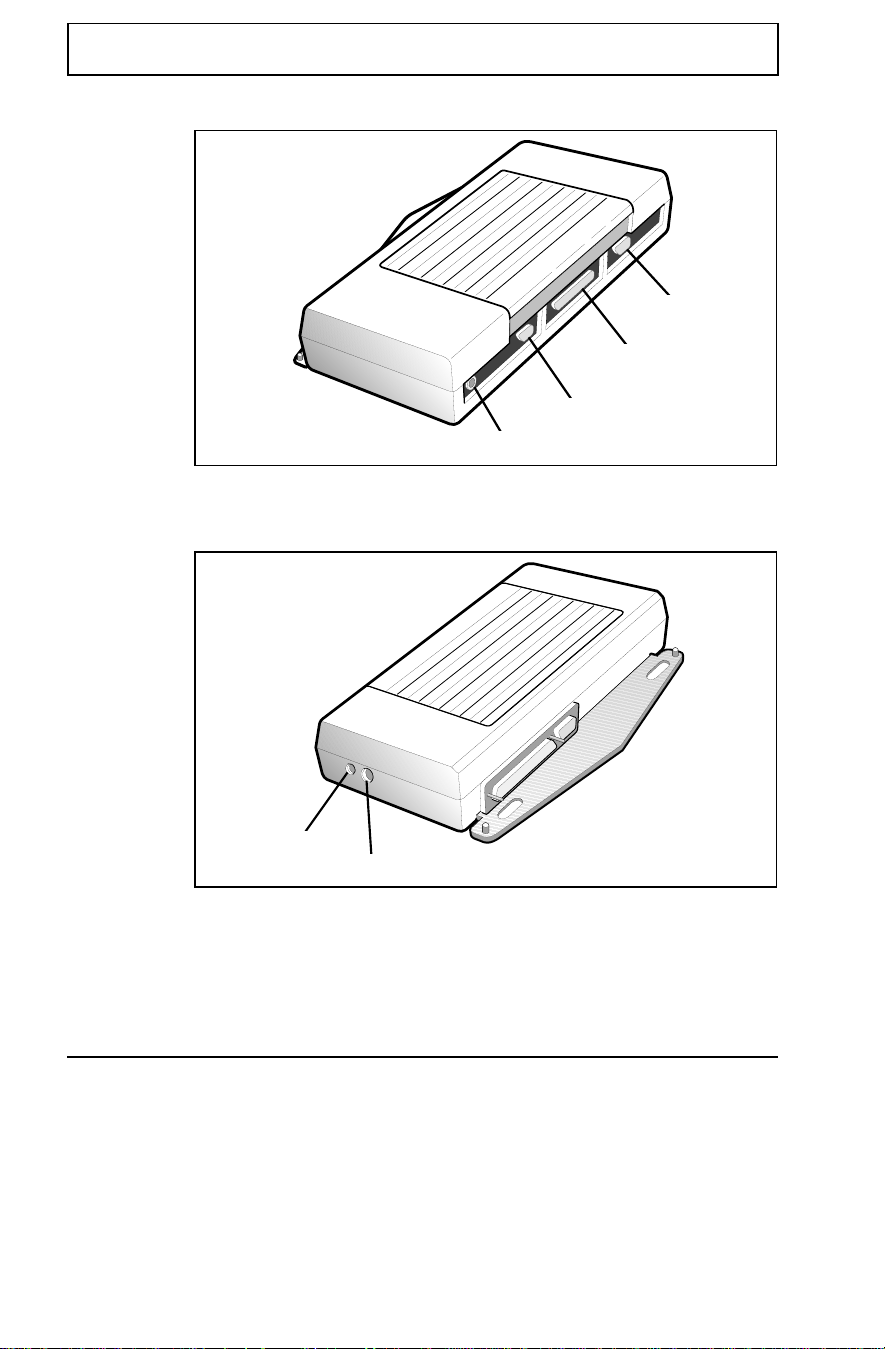
Features
Your DockMate includes the following features:
Features
Serial
Parallel
VGA
PS/2
1-2 Features
Power
PS/2
Page 10

n
DockMate Installation
This Chapter Explains:
How to unpack and inventory the system components
❏
Software installation
❏
Hardware installation
❏
Note: After completion of the hardware installation, you
must configure TI Setup or SetDock programs as described
in Chapter 3 of this manual.
Contents
Unpacking Instructions ...........................................2-2
DockMate Software Installation...............................2-3
DockMate Hardware Installation..............................2-5
Docking the Notebook .............................................. 2-5
Installing an External PS/2 Option .......................... 2-6
Serial Port Connections............................................ 2-6
Parallel Port Connections ......................................... 2-7
Video Connector....................................................... 2-7
AC Connection ......................................................... 2-7
2
DockMate Installation 2-1
Page 11

Unpacking Instructions
The DockMate is shipped with the following hardware
components:
DockMate
❏
DockMate User’s Guide (this manual)
❏
Accessory Kit
❏
Unpack the DockMate using the following instructions:
1. Carefully cut the tape that seals the top flap of the
shipping carton.
2. Remove the DockMate and all accessories from the
shipping carton.
3. Remove all protective coverings from the DockMate
and accessories, and inventory the contents. Save
shipping container and packaging if shipping is
required in the future.
Unpacking Instructions
2-2 DockMate Installation
Page 12

n
DockMate Software Installation
A DockMate System Installation diskette is provided with
your DockMate. Software on this diskette updates the
TravelMate BIOS software with the latest version that
supports your DockMate. If your TravelMate has a newer
version of BIOS than the one on the diskette, the program
will not change the BIOS on your system.
For your TM5000 Series computer to work correctly with
the DockMate, you must upgrade the BIOS (Basic
Input/Output System) with new firmware (FLASH ROM).
To upgrade the BIOS, complete the following steps:
1. Turn off power to your notebook computer.
2. Ensure the system is undocked.
3. Place the DockMate Installation diskette into drive A.
4. Turn on power to your notebook computer.
5. Follow instructions on the screen.
Note: If your system BIOS is more current than the BIOS
on the diskette, your system BIOS is not updated and you
are taken to the MS-DOS
remove the diskette and reboot.
®
prompt. If this is the case,
DockMate Software Installation
6. When finished, remove the floppy disk and slide the
power switch off then on to boot.
7. During the boot process you will hear a beep.
Immediately press Ctrl-Alt-Esc.
8. If you have previously changed the configuration of TI
Setup for special hardware requirements, note the
settings before continuing to the next step. Reload
them later as required by your hardware.
9. From the Setup menu, press Esc-F5 to load factory
defaults.
DockMate Installation 2-3
Page 13

DockMate Software Installation
10. Press Esc-F4 to save the configuration.
The installation process is complete and your computer
reboots.
Note: When using a DockMate, plug the AC adapter
supplied with your TravelMate 5000 into the DockMate. All
n
n
power on or off is then controlled by the notebook’s power
switch.
Note: Some TM5000 Series notebooks may experience
PCMCIA recognition problems when docked to a DockMate.
Troubleshooting procedures are located in Chapter 4,
Troubleshooting Procedures.
2-4 DockMate Installation
Page 14

DockMate Hardware Installation
Docking the Notebook
Use the following procedure to dock your notebook
computer:
1. Clear an area on your workstation surface to permit
both units to be flat on the table or desktop while
performing the initial docking procedure.
2. Ensure that the rear port covers on the TM5000 are
open.
3. Lift the lever on top of the DockMate so that the guide
pin plate is extended.
4. Carefully match the holes on the underside of the
notebook with the guide pins protruding from the
DockMate and press down on the top lever to dock.
DockMate Hardware Installation
n
Inserting the notebook
Note: To undock the noteboook, lift up the lever and lift
the notebook off the docking pegs.
DockMate Installation 2-5
Page 15

DockMate Hardware Installation
Installing an External PS/2® Option
The DockMate allows you to attach any of the following to
the 6-pin PS/2 connectors on the system:
external keyboard (side port recommended)
❏
external PS/2 mouse (rear port recommended)
❏
external numeric keypad (rear or side port)
❏
To install the external PS/2 option, connect a round PS/2
connector cable to the 6-pin circular connector on the rear
or side of the system.
Serial Port Connections
Your DockMate is equipped with a 9-pin serial port with
16550 UART that can be attached to any external serial
device such as:
external modem
❏
serial printer
❏
any device that uses an RS-232 interface
❏
When using the Serial Port connection on the DockMate,
the Serial Port connector on the notebook is disabled.
Caution: Never connect a parallel device to a serial
c
2-6 DockMate Installation
port, or a serial device to a parallel port or video port;
this may cause damage to the DockMate. If you are
uncertain as to what type connector the external
device has, refer to the technical manual for the
external device.
Page 16

n
DockMate Hardware Installation
Parallel Port Connections
Your DockMate is equipped with one DB25 (25-pin)
bidirectional parallel port (device name LPT1). This port
occupies address 0378h, and is designated as LPT1
(default value). Typically, the notebook computer sends
print data to LPT1 unless the menu is configured otherwise.
When using the Parallel Port connection on the DockMate,
the Parallel Port connector on the notebook is disabled.
Video Connector
To install an external VGA monitor (optional), connect the
VGA cable connector to the 15-pin connector on the rear of
the DockMate. The DockMate supports all external
monitors supported by the TM5000. For further
information, refer to the TravelMate 5000 User’s Guide.
Note: Refer to the TravelMate 5000 User’s Guide and User’s
Reference Guide for information on VGA utilities.
AC Connection
Your DockMate must run off of AC power by connecting a
TI AC adapter (TI Part No. 9786094-0003) to the system.
DockMate is designed to be powered by an AC adapter that
is attached to either the connected notebook or to the
DockMate (power transfers through the expansion bus
pins).
c
Caution: Only a TM5000 AC adapter, TI Part No.
9786094-0003, can be connected to a DockMate.
DockMate Installation 2-7
Page 17

Utilities
This chapter tells you about:
Using DockMate utilities
❏
Contents
Introduction ....................................................... 3-2
Using TI Setup ....................................................3-3
Using the SetDock Utility.................................... 3-5
Running SetDock .................................................3-5
SetDock Key Functions ........................................3-6
Exiting SetDock....................................................3-7
3
Utilities 3-1
Page 18

Introduction
TI provides two utilities that are copied to your system
when you install software from the DockMate System
Installation diskette:
TI Setup - for use with Windows 95 and Windows for
❏
Workgroups
SetDock - for use with MS-DOS
❏
These utilities allow advanced users to configure special
operating modes or parameters for hardware attached to
the TravelMate notebook or the DockMate.
Introduction
3-2 Utilities
Page 19

Using TI Setup
n
TI Setup is copied onto your system at the time you install
the DockMate Installation diskette. TI Setup is used to
configure peripheral hardware attached through your
DockMate. TI Setup is used in either Windows or Windows
95 environments.
To configure peripherals for use with your system, complete
the following steps:
1. Complete the following for your operating system:
If you are using Windows 95 - Double-click on TI
❏
Setup in the Control Panel
If you are using Windows for Workgroups -
❏
Double-click on TI Setup in the TravelMate
Notebook Center group
2. Select the tab labeled Ports-Dock A.
3. Under Dock Type, use the pulldown menu (by selecting
the ▼) and single-click on DockMate.
4. Using configuration information provided with your
peripheral device, change any required settings in this
window.
Note: A Ports-Dock B tab (identical to the Ports-Dock A
tab) is provided in case you have more than one type of
DockMate system and want to maintain settings for both
types. If both Ports Dock A and B are set to the same type
of DockMate system, only Ports Dock A settings are used.
The Ports - Undocked tab indicates settings for your
TravelMate notebook when undocked from the DockMate.
Using TI Setup
Utilities 3-3
Page 20

Using TI Setup
The following table provides a synopsis of all options
available on the Ports-Dock A or Ports-Dock B tabs:
Item Options Description
Dock Type
Dock 9 Pin
None (default)
DockMate
DockMate Plus
DockMate Net Ready
DockMate
General Pn’P Dock
Off
COM1 (default)
COM2
COM3
COM4
Allows you to select the
type of docking station
attached to your notebook.
General Pn’P Dock provides
auto setup for any
operating system that
supports true Plug ’N Play.
Allows you to disable or set
the port address used for
the notebook or docking
system serial port.
Notebook SIR
Dock SIR
COM3/COM4
Dock Parallel Port Address
Dock Parallel Port
Extended Mode
Off
COM1 (default)
COM2
COM3
COM4
Off
COM1 (default)
COM2
COM3
COM4
338h/238h
3e8h/2e8h (default)
2e8/2e0
Off
3BCh
378h (default)
278h
Off (default)
SPP
EPP and SPP
ECP
ECP and EPP
Allows you to disable or set
the port address used for
the docking system serial
infrared port.
Allows you to disable or set
the port address used for
the docking system port.
Allows you to select the
address at which COM
ports 3 and 4 operate.
Allows you to select the
address at which the
parallel port operates.
Allows you to select the
protocol for bidirectional
operation (printers or
parallel network adapters).
3-4 Utilities
Page 21

Using the SetDock Utility
SetDock is copied onto your system at the time you install
the DockMate Software Installation diskette. The SetDock
utility is used in the DOS environment only. Like TI Setup,
it configures your system for use with peripheral devices. If
you are using Windows or Windows 95, use TI Setup when
you add or change peripherals. For more information on
options available on SetDock screens, refer to the table in
the Using TI Setup section of this chapter.
Running SetDock
To run SetDock from MS-DOS, go to the UTILS directory
(C:\UTILS) and type
SETDOCK.EXE
and press Enter. The SetDock main screen then appears
on your monitor.
TravelMate 5000 Dock Setup Program
Version 1.20 Dec 20 1995
Dock Configuration ’A’ Page 1 of 2
Dock Type: DockMate
Serial Ports Dock Parallel Port
Dock 9 Pin: COM1 Address: 378h
Notebook SIR: Off Extended Mode: ECP and EPP
Dock SIR (if present) Off
COM3/COM4 Addresses: 3e8/2e8
Using the SetDock Utility
Select the type of docking station
Esc=Exit F1= Help
SETDOCK page 1 of 2
↑↓
Field +/- Value PgUp/PgDn
Utilities 3-5
Page 22

Using the SetDock Utility
Note: A Dock Configuration B screen (page 2 of 2) is
provided in case you have more than one type of DockMate
n
system and want to maintain settings for both. If both Dock
Configurations A and B are set to the same type of
DockMate system, only Ports Dock A settings are used.
SetDock Key Functions
To use SetDock utility screens, the following keys are
provided.
Key Function
↑
↓
↑ ↓ Moves up or down through the list of fields
Tab Moves down through the list of fields
Esc Displays a screen with Exit options
F1 Provides help
+/- Moves forward or backward through the values
Spacebar Moves forward through the values available for
PgUp
PgDn
Moves forward or backward through values
available for the selected field
available for the selected field
the selected field
Switches between Dock Configuration A and
Dock Configuration B
3-6 Utilities
Page 23

Using the SetDock Utility
Exiting SetDock
To leave the SetDock utility, complete the following steps:
1. Press Esc.
The Exiting Setup Menu appears.
2. Select one of the following options:
Key Function
Esc Returns you to the main screen
F4 Saves all changes, exits Setup, and reboots
F5 Loads default values for all pages. Use this setting to reload
F6 Aborts Setup without saving values
values if you have had problems during configuration.
Esc-F4
Press
afterward to save and exit.
Utilities 3-7
Page 24

n
Troubleshooting Procedures
This Chapter Provides Tips for:
Network Connection
❏
Application-related anomalies
❏
Note: For other troubleshooting tips, refer to the
README.TXT file on the DockMate Installation diskette.
Contents
Notebook Connection ..............................................4-2
Option Installation..................................................4-3
Ports ........................................................................ 4-3
Printer ..................................................................... 4-3
PCMCIA Card Recognition .......................................4-5
Windows 95 (TI-Installed)......................................... 4-5
Windows 95 (Commercial Upgrade) .......................... 4-6
All Windows 95 Systems .......................................... 4-9
Windows for Workgroups v3.11 ................................ 4-9
4
Troubleshooting Procedures 4-1
Page 25

Notebook Connection
Visually inspect the notebook and verify that the
❏
notebook is docked properly (refer to Chapter 2,
Dockmate Installation).
Visually inspect the connectors on the notebook to
❏
ensure there is no physical damage to the connector
areas of the notebook.
Ensure that you are using the correct AC adapter (TI
❏
Part No. 9786094-0003).
Try disconnecting the notebook and running notebook
❏
diagnostics to isolate the problem to either the
notebook or the DockMate.
For further information, refer to Appendix D,
Diagnostics in the online TravelMate 5000 Series
Notebook Computer User’s Reference Guide for a
description of the error code messages.
Try cycling power on the notebook.
❏
Notebook Connection
4-2 Troubleshooting Procedures
Page 26

Option Installation
If you experience difficulty with a serial device, parallel
device, PS/2 device, or external VGA monitor, disconnect
the DockMate. Connect the peripheral to the notebook. If
it runs properly, you can determine that the anomaly lies
with the DockMate and not with your peripheral or with the
notebook.
Ports
If you are running Windows for Workgroups, Windows 95,
or MS-DOS and an external device (such as a printer) is
failing, check the following:
1. Ensure that the device’s I/O cable is the correct type
for the port and is securely installed.
2. Ensure that the external device is powered up and
properly connected to the DockMate System and that
the external device is properly configured (refer to
Chapter 2, DockMate Hardware Installation).
3. If you are experiencing a failure on the serial port,
check to see that the serial port is correctly configured
to match the settings in the external device (refer to
Chapter 4). If your application software does not
initialize the serial ports, you must use the MS-DOS
MODE command in your AUTOEXEC.BAT file (refer to
your online MS-DOS User’s Manual for further
instructions).
Option Installation
Printer
If you are running Windows 95 and are experiencing
problems with printing, complete the following steps:
1. From the Windows Control Panel, select the System
icon.
2. Select the Device Manager.
3. Select the Printer port.
4. Verify that the I/O Range is 378-037A.
Troubleshooting Procedures 4-3
Page 27

Option Installation
5. Verify that the IRQ is set to 07.
6. Select OK.
4-4 Troubleshooting Procedures
Page 28

PCMCIA Card Recognition
On some TravelMate Pentium products, a PCMCIA Ethernet
card error may occur after DockMate installation. If this
happens, refer to the following sections (Windows 95,
Windows 95 Commercial Upgrade, or Windows for
Workgroups) depending on your operating environment.
Windows 95 (TI-Installed)
The following instructions should clear PCMCIA Ethernet
card problems in a TI-installed Windows 95 environment.
Reconfigure TI Setup
1. Open the Windows Control Panel and select the TI
Setup icon.
2. Select the System Configuration tab and set the
parameter for PCMCIA I/O Addresses to Maximum.
3. Select the tab marked Ports-Dock A.
4. Select DockMate for the Dock Type.
5. Select Dock Parallel Port Extended Mode.
PCMCIA Card Recognition
6. Choose one of the following as the recommended
settings for docking:
SPP is selected as Standard Parallel Port
❏
ECP and EPP is selected as Extended Parallel Port
❏
(setting preferred for most users).
7. Select OK.
8. Reboot and proceed to Reconfigure System Information.
Reconfigure System Information
1. Select the System icon in the Control Panel.
2. Select the Device Manager tab.
Troubleshooting Procedures 4-5
Page 29

PCMCIA Card Recognition
3. Double-click on the Ports (COM & LPT) option.
A list of selections appears.
4. Double-click on Communications Port (COM2).
The COM2 configuration is displayed.
5. Select the General tab.
6. Deselect Dock 1 (Current) located in the Device Usage
area.
7. Select OK/Close to close the Communications Port
Properties window.
8. Select OK/Close to close the System Properties
window.
9. Select the Start icon at the bottom of your screen.
10. Select Shutdown.
11. Select Restart the computer.
12. Select Yes.
The notebook restarts and the error should be cleared.
Windows 95 (Commercial Upgrade)
This version of Windows 95 is not TI-installed. If you are
running the Windows 95 commercial upgrade, these
instructions should clear PCMCIA Ethernet card problems.
Reconfigure TI Setup
1. Open the Windows Control Panel and select the TI
Setup icon.
2. Select the System Configuration tab and set the
parameter for PCMCIA I/O Addresses to Maximum.
3. Select the Dock A tab.
4-6 Troubleshooting Procedures
Page 30

PCMCIA Card Recognition
4. Select DockMate as the Dock Type.
5. Select OK.
You are prompted to reboot.
6. Reboot and proceed to Reconfigure System Information.
Windows 95 starts configuring unknown hardware (this
may happen multiple times and is a standard operation
for Plug ’n Play in Windows 95).
Reconfigure System Information
The following steps allow you to reconfigure system
information for the Windows 95 Commercial Upgrade.
Checking Device Settings
1. Go to the System icon located in the Control Panel.
2. Select the Device Manager tab.
3. Select Modem from the Device Manager tab.
4. Select Resources after selecting the modem being used
and ensure that the modem is set to IRQ 3 and an
address 3e8.
5. Select Resources after selecting PCMCIA socket and
verify that the PCMCIA socket is not turned off.
Remove Ports and Devices
1. Go to the System icon located in the Control Panel.
2. Select Ports (COM & LPT) from the Device Manager tab.
3. Select and remove all communications ports except
COM1.
4. Select and remove all PCMCIA devices.
5. Remove PCMCIA hardware devices from the TravelMate
notebook.
Troubleshooting Procedures 4-7
Page 31

PCMCIA Card Recognition
6. Close the System Properties window and restart the
system.
Update Device Usage
1. Go to the System icon located in the Control Panel.
2. Select Ports (COM & LPT) from the Device Manager tab.
3. Double-click on Communication Port (COM2).
4. Select the General tab.
5. Deselect Dock 1 (Current) located in the Device Usage
area.
6. Select OK.
Reinstall Hardware
1. Reinstall all PCMCIA hardware devices one at a time.
Windows 95 should automatically configure software for
each device.
2. Select the Refresh button on the System Properties
screen and check and correct any conflicts.
Note: Conflicts are indicated by a yellow
n
4-8 Troubleshooting Procedures
the device icon would normally be. Go to the Resources tab
to see detailed information about the conflict.
Turn off Automatic Settings
1. Go to the System icon located in the Control Panel.
2. Select Ports (COM & LPT) from the Device Manager tab.
3. Double-click on the icon for each device you have added.
Configuration properties for the selected device appear.
4. Select Resources.
c
symbol where
Page 32

PCMCIA Card Recognition
5. Ensure that Use automatic settings is deselected.
Accept Configuration Changes
1. Select OK to close the System Properties window.
2. Close the Control Panel.
3. Select the Start icon at the bottom of your screen.
4. Select Shutdown.
5. Select Restart the computer.
6. Select Yes.
The notebook restarts and the error should be cleared.
All Windows 95 Systems
If you are still experiencing PCMCIA recognition problems
using a Windows 95 system, complete the following steps:
1. Open the Control Panel.
2. Select the PC Card (PCMCIA) icon.
3. Select the Global Setting tab.
4. Deselect Automatic Settings.
5. Change the Start field to 000C8000.
6. Change the End field to 007FFFFF.
7. Verify that the Length field is 00001000.
8. Select OK.
9. Select Yes to restart.
Windows for Workgroups v3.11
If you are running Windows for Workgroups v3.11, the
following instructions should clear problems with your
PCMCIA card:
Troubleshooting Procedures 4-9
Page 33

PCMCIA Card Recognition
1. Go to TI Setup (located in the TravelMate Notebook
Center group) and select the System Configuration
tab.
2. Ensure that the PCMCIA I/O is changed from
Minimum to Maximum.
3. Press Esc-F4 to save the configuration.
4. Select the Ports-Dock A.
5. Select the correct DockMate type for your DockMate
(DockMate, DockMate, DockMate Plus, DockMate
Multimedia, etc.).
6. Select OK.
You are prompted to reboot.
7. Reboot the computer.
4-10 Troubleshooting Procedures
Page 34

Appendix A
Reference Material
Other Manuals About the System
The following documents provide additional information
about the DockMate System:
Product Manual Part Number
TravelMate 5000 User’s Guide online
Maintenance Manual 9786166-0001
User’s Reference Guide online
Windows for Workgroups
3.11
Windows 95 User’s Guide online
MS-DOS User’s Manual online
User’s Guide online
Reference Material A-1
Page 35

Appendix B
DockMate Specifications
Specifications for the DockMate System are provided in the
following table.
DockMate System Specifications
Specification Type Value
Physical Dimensions Width 11.0 inches
Depth 5.77 inches
Height 2.48 inches
Weight 1.84 lbs. without options
Power Adapter Input 100 to 240 VAC
Frequency 50 to 60 Hz
Current 0.3 to 0.6 A
Output 0.6 to 0.3 A
Temperature Operating 50 to 104 degrees F
Storage/Transit -4 to 140 degrees F
Humidity Operating 20 to 80 percent, non-condensing
Non-Operating 10 to 90 percent, non-condensing
Altitude Operating -1,000 ft. to 10,000 ft.
Non-Operating -1,000 ft. to 10,000 ft.
Maximum of 36 Watts
(10 to 40 degrees C)
(-20 to 60 degrees C)
DockMate Specifications B-1
Page 36

Appendix B
DockMate System Specifications
Specification Type Value
Appendix B
Appendix B
Shock Operating 6 G applied in six
orientations (pos. and neg.
X, Y, and Z axes)
Non-Operating 35 G in X , Y, and Z axes
Vibration Operating 0.5 G, 5 to 500 Hz
Non-Operating 0.5 G, 5 to 500 Hz
Agency Approvals Underwriter’s Laboratory
(UL) Standard 1950 (safety)
Canadian UL listed
C22.2 No. 950
(safety)
EN60950, TUV Rheinland
(safety)
FCC CFR 47, Part 15, Subpart
B, FCC Level B (RFI/EMI))
Canadian Department of
Communications (DOC)
Certification (RFI/EMI)
VDE 0878, Class B (RFI/EMI)
CISPR-22/EN55022 Class B
(RFI/EMI)
B-2 DockMate Specifications
Page 37

Index
A
AC adapter .............................. 2-7, 4-2
adapter cards .......................4-5 - 4-10
B
BIOS............................................... 2-3
D
diagnostics ..................................... 4-2
DockMate
docking...................................... 2-5
features ..................................... 1-1
software..................................... 2-1
System Installation diskette ....... 2-3
undocking.................................. 2-5
unpacking.................................. 2-2
Dock Type ...................................... 3-4
M
MS-DOS ......................................... 4-3
MTTOOL............................... 4-5 - 4-10
N
network
drivers .............................4-5 - 4-10
Ethernet .................................... 4-5
O
options ...................................4-3 - 4-4
parallel ............................... 2-6, 4-3
serial .................................. 2-7, 4-3
P
parallel device................................. 4-3
PCMCIA.......................................... 4-5
Port ................................................ 4-3
com ........................................... 3-4
parallel........................ 1-1, 2-7, 3-4
PS/2....................................1-1, 2-6
serial ........................... 1-1, 2-6, 3-4
VGA.....................................1-1, 2-7
power..............................................2-4
printer.............................................4-3
PS/2 device.....................................4-3
S
serial device ....................................4-3
serial port.................................1-1, 3-4
SetDock ...................................3-2, 3-5
exiting ........................................3-7
key functions..............................3-6
running ......................................3-5
software ..........................................2-3
T
TI Setup ..................3-2 - 3-3, 4-5 - 4-6
troubleshooting...............................4-1
V
VGA .........................................2-7, 4-3
W
Windows 95...................... 2-3, 4-3, 4-5
PCMCIA recognition....................4-5
PCMCIA recognition problems.....4-9
reconfiguring system info............4-5
reconfiguring TI Setup ................4-5
Windows 95 Commercial
Upgrade............................... 4-5 - 4-6
PCMCIA recognition....................4-6
reconfiguring system
information..............................4-7
reconfiguring TI Setup ................4-6
Windows for Workgroups ..........2-3, 4-5
PCMCIA recognition....................4-9
Windows for Workgroups 3.11 .........4-9
Index 1
 Loading...