

Page 1
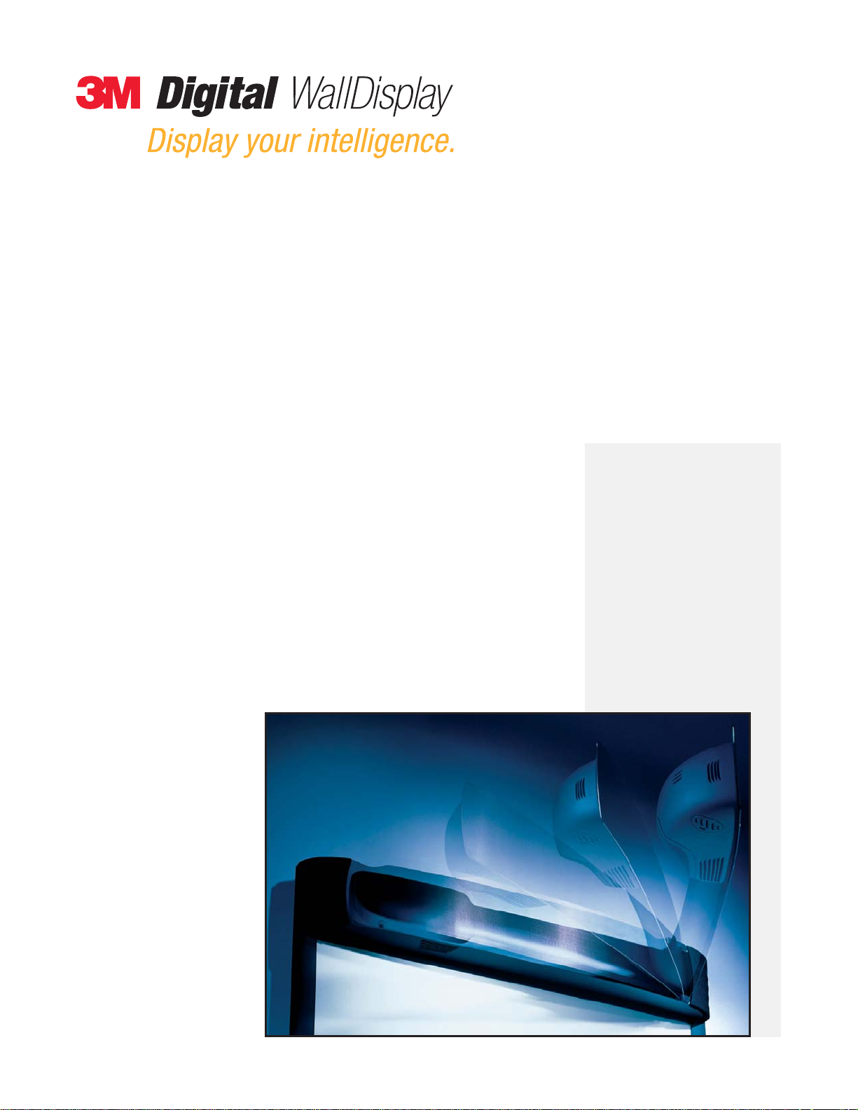
Operator ’s Guide
…with copyboard
8100CB
…interactive whiteboard
8200IW
…deluxe interactive whiteboard
8200IC
July 2003
78-6970-9185-4 Rev. A
Copyright © 2003, 3M.
All Rights Reserved.
Page 2

(This page intentionally left blank for printed version)
Page 3

Contents
Introduction
Thank You for Choosing 3M . . . . . . . . . . . . . . . . . . . . . . . . . . . . . . . . . . . . . . . . . . . . . . . . . . . . . . . .5
Intended Use . . . . . . . . . . . . . . . . . . . . . . . . . . . . . . . . . . . . . . . . . . . . . . . . . . . . . . . . . . . . . . . . . . . .5
Safety Precautions . . . . . . . . . . . . . . . . . . . . . . . . . . . . . . . . . . . . . . . . . . . . . . . . . . . . . . . . . . . . . . . .5
Product Safety Label . . . . . . . . . . . . . . . . . . . . . . . . . . . . . . . . . . . . . . . . . . . . . . . . . . . . . . . . . . . . . .7
Trademarks . . . . . . . . . . . . . . . . . . . . . . . . . . . . . . . . . . . . . . . . . . . . . . . . . . . . . . . . . . . . . . . . . . . . .8
3M Digital WallDisplay Technical Support . . . . . . . . . . . . . . . . . . . . . . . . . . . . . . . . . . . . . . . . . . . . .8
FCC Statement—Class A . . . . . . . . . . . . . . . . . . . . . . . . . . . . . . . . . . . . . . . . . . . . . . . . . . . . . . . . . .9
EEC Statement—Class A . . . . . . . . . . . . . . . . . . . . . . . . . . . . . . . . . . . . . . . . . . . . . . . . . . . . . . . . . .9
Model Identification and Differences . . . . . . . . . . . . . . . . . . . . . . . . . . . . . . . . . . . . . . . . . . . . . . . . . .10
Contents . . . . . . . . . . . . . . . . . . . . . . . . . . . . . . . . . . . . . . . . . . . . . . . . . . . . . . . . . . . . . . . . . . . . . . .11
Optional Accessories . . . . . . . . . . . . . . . . . . . . . . . . . . . . . . . . . . . . . . . . . . . . . . . . . . . . . . . . . . . . . .11
What’s Next? . . . . . . . . . . . . . . . . . . . . . . . . . . . . . . . . . . . . . . . . . . . . . . . . . . . . . . . . . . . . . . . . . . . .11
Part Identification . . . . . . . . . . . . . . . . . . . . . . . . . . . . . . . . . . . . . . . . . . . . . . . . . . . . . . . . . . . . . . . .12
3M Digital WallDisplay Features . . . . . . . . . . . . . . . . . . . . . . . . . . . . . . . . . . . . . . . . . . . . . . . . . . . . .13
System Setup
Connecting to Various Equipment . . . . . . . . . . . . . . . . . . . . . . . . . . . . . . . . . . . . . . . . . . . . . . . . . . . .14
Operation
Startup . . . . . . . . . . . . . . . . . . . . . . . . . . . . . . . . . . . . . . . . . . . . . . . . . . . . . . . . . . . . . . . . . . . . . . . .15
Shutdown . . . . . . . . . . . . . . . . . . . . . . . . . . . . . . . . . . . . . . . . . . . . . . . . . . . . . . . . . . . . . . . . . . . . . .16
Remote Control Unit
Features . . . . . . . . . . . . . . . . . . . . . . . . . . . . . . . . . . . . . . . . . . . . . . . . . . . . . . . . . . . . . . . . . . . . . . . .17
Installing or Replacing Batteries . . . . . . . . . . . . . . . . . . . . . . . . . . . . . . . . . . . . . . . . . . . . . . . . . . . . .20
Digital Markers and Eraser
Assembling Digital Markers . . . . . . . . . . . . . . . . . . . . . . . . . . . . . . . . . . . . . . . . . . . . . . . . . . . . . . . .21
Assembling Digital Eraser . . . . . . . . . . . . . . . . . . . . . . . . . . . . . . . . . . . . . . . . . . . . . . . . . . . . . . . . . .22
Menu System
Menu Navigation . . . . . . . . . . . . . . . . . . . . . . . . . . . . . . . . . . . . . . . . . . . . . . . . . . . . . . . . . . . . . . . . .23
Using the 3M™ Digital WallDisplay as a Copyboard or Digital Whiteboard
Copyboard Mode . . . . . . . . . . . . . . . . . . . . . . . . . . . . . . . . . . . . . . . . . . . . . . . . . . . . . . . . . . . . . . . . .29
Whiteboard Mode (8200IC Only) . . . . . . . . . . . . . . . . . . . . . . . . . . . . . . . . . . . . . . . . . . . . . . . . . . . .29
Projection Mode (8200IC Only) . . . . . . . . . . . . . . . . . . . . . . . . . . . . . . . . . . . . . . . . . . . . . . . . . . . . .29
Using Copyboard Mode . . . . . . . . . . . . . . . . . . . . . . . . . . . . . . . . . . . . . . . . . . . . . . . . . . . . . . . . . . . .29
Using Whiteboard Mode . . . . . . . . . . . . . . . . . . . . . . . . . . . . . . . . . . . . . . . . . . . . . . . . . . . . . . . . . . .30
Installing eBeam on Your Computer . . . . . . . . . . . . . . . . . . . . . . . . . . . . . . . . . . . . . . . . . . . . . . . . . .30
Using Projection Mode . . . . . . . . . . . . . . . . . . . . . . . . . . . . . . . . . . . . . . . . . . . . . . . . . . . . . . . . . . . .32
Maintenance
General Maintenance . . . . . . . . . . . . . . . . . . . . . . . . . . . . . . . . . . . . . . . . . . . . . . . . . . . . . . . . . . . . . .33
Lamp Usage . . . . . . . . . . . . . . . . . . . . . . . . . . . . . . . . . . . . . . . . . . . . . . . . . . . . . . . . . . . . . . . . . . . .33
Onscreen Lamp Messages . . . . . . . . . . . . . . . . . . . . . . . . . . . . . . . . . . . . . . . . . . . . . . . . . . . . . . . . . .33
Lamp Replacement . . . . . . . . . . . . . . . . . . . . . . . . . . . . . . . . . . . . . . . . . . . . . . . . . . . . . . . . . . . . . . .34
Resetting Lamp Hours . . . . . . . . . . . . . . . . . . . . . . . . . . . . . . . . . . . . . . . . . . . . . . . . . . . . . . . . . . . . .37
Replacing Projection Screen . . . . . . . . . . . . . . . . . . . . . . . . . . . . . . . . . . . . . . . . . . . . . . . . . . . . . . . .38
Troubleshooting
Common Problems and Solutions . . . . . . . . . . . . . . . . . . . . . . . . . . . . . . . . . . . . . . . . . . . . . . . . . . . .39
3
3M™ Digital WallDisplay
©3M 2003. All Rights Reserved.
Page 4

Onscreen Messages . . . . . . . . . . . . . . . . . . . . . . . . . . . . . . . . . . . . . . . . . . . . . . . . . . . . . . . . . . . . . . .40
eBeam Software . . . . . . . . . . . . . . . . . . . . . . . . . . . . . . . . . . . . . . . . . . . . . . . . . . . . . . . . . . . . . . . . .41
Network Connection/Shared Meetings . . . . . . . . . . . . . . . . . . . . . . . . . . . . . . . . . . . . . . . . . . . . . . . . .42
Writing/Data Capture . . . . . . . . . . . . . . . . . . . . . . . . . . . . . . . . . . . . . . . . . . . . . . . . . . . . . . . . . . . . .43
EFI Meeting Applet . . . . . . . . . . . . . . . . . . . . . . . . . . . . . . . . . . . . . . . . . . . . . . . . . . . . . . . . . . . . . . .45
Background Images . . . . . . . . . . . . . . . . . . . . . . . . . . . . . . . . . . . . . . . . . . . . . . . . . . . . . . . . . . . . . . .46
Service Information
Parts and Accessories . . . . . . . . . . . . . . . . . . . . . . . . . . . . . . . . . . . . . . . . . . . . . . . . . . . . . . . . . . . . .47
Optional Accessories . . . . . . . . . . . . . . . . . . . . . . . . . . . . . . . . . . . . . . . . . . . . . . . . . . . . . . . . . . . . . .47
Ordering Parts or Getting Information . . . . . . . . . . . . . . . . . . . . . . . . . . . . . . . . . . . . . . . . . . . . . . . . .47
Appendix
3M Digital WallDisplay Specifications . . . . . . . . . . . . . . . . . . . . . . . . . . . . . . . . . . . . . . . . . . . . . . . .48
Input/Output Signal Specifications . . . . . . . . . . . . . . . . . . . . . . . . . . . . . . . . . . . . . . . . . . . . . . . . . . .49
Computer Compatibility . . . . . . . . . . . . . . . . . . . . . . . . . . . . . . . . . . . . . . . . . . . . . . . . . . . . . . . . . . .49
Printer Compatibility . . . . . . . . . . . . . . . . . . . . . . . . . . . . . . . . . . . . . . . . . . . . . . . . . . . . . . . . . . . . . .50
4
Contents
3M™ Digital WallDisplay
©3M 2003. All Rights Reserved.
Page 5
Introduction
Thank You for Choosing 3M
Thank you for choosing 3M equipment. This product has been produced in accordance with 3M’s highest quality
and safety standards to ensure smooth and troublefree use in the years to come.
For optimum performance, please follow the operating instructions carefully. We hope you will enjoy using this
high performance product in your meetings, presentations, and training sessions.
Intended Use
Before operating this machine, please read the entire manual thoroughly. The 3M Digital WallDisplay Systems
are designed, built, and tested for use indoors, using 3M lamps, 3M mount hardware, and nominal local voltages.
The use of other replacement lamps, outdoor operation, or different voltages has not been tested and could damage the projector or peripheral equipment and/or create a potentially unsafe operating condition.
3M Digital WallDisplay Systems are designed to operate in a normal office environment.
• 16° to 29° C (60° to 85° F)
• 10 to 80% RH (without condensation)
• 0 to 3048 m (0 to 10,000 feet) above sea level
The ambient operating environment should be free of airborne smoke, grease, oil and other contaminants that
can affect the operation or performance of the 3M Digital WallDisplay (3M DWD).
Use of this product in adverse conditions will void the product warranty.
Safety Precautions
Read and understand all instructions before using. Pay particular attention to areas where this symbol is
shown:
Note: Emphasizes important conditions or details.
•Close supervision is necessary when any appliance is used by or near children. Do not leave appliance
unattended while in use.
•Never look directly into the projector lens when the lamp is on. The short-arc mercury lamp produces
a strong light that could damage your eyesight.
•Care must be taken, as burns can occur from touching hot parts when replacing the lamp.
•Do not operate appliance with a damaged cord or if the appliance has been dropped or damaged, until
it has been examined by a qualified service technician.
•Position the cord so that it will not be tripped over, pulled or placed in contact with hot surfaces.
• If an extension cord is necessary, a cord with a current rating at least equal to that of the appliance
should be used. Cords rated for less amperage than the appliance may overheat.
•Always unplug appliance from electrical outlet before cleaning and servicing and when not in use.
Grasp plug and pull to disconnect.
•To reduce the risk of electric shock, do not immerse this appliance in water or other liquids.
WARNING
Indicates a potentially hazardous situation which, if not
avoided, could result in death or serious injury.
CAUTION
Indicates a potentially hazardous situation which, if not
avoided, could result in minor or moderate injury. It may
also be used to alert against unsafe practices.
5
3M™ Digital WallDisplay
©3M 2003. All Rights Reserved.
Page 6

6
Introduction
3M™ Digital WallDisplay
©3M 2003. All Rights Reserved.
Safety Precautions
•To reduce the risk of electric shock, do not disassemble this appliance. Request a qualified technician
when service or repair work is required. Incorrect reassembly can cause electric shock when the
appliance is subsequently used.
• Connect this appliance to a grounded outlet.
•Keep all ventilation openings free of any obstructions.
• The projection lamp contains mercury. Always dispose of this lamp in a proper manner according to
local regulations.
•Do not apply force to the projection arm. This may cause permanent damage to the unit or may cause
personal injury.
•Do not manually open or close the projection arm while the 3M Digital WallDisplay is in operation.
• The 3M Digital WallDisplay’s projection arm is motorized, and extends 42˝ (106 cm) from the installation while in use. Caution should be taken when operating or walking near the 3M Digital
WallDisplay. It is possible a tall person’s head or an upraised hand could come in contact with the projection arm.
•Do not place the product in direct sunlight, near heaters or heat radiating appliances.
Page 7
Introduction
7
3M™ Digital WallDisplay
©3M 2003. All Rights Reserved.
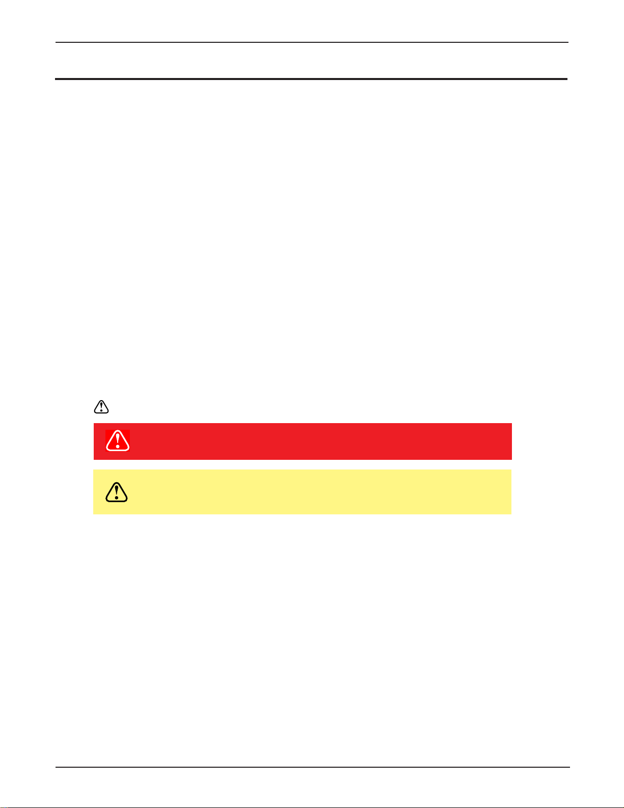
Product Safety Label
The following safety label is used on or within the 3M Digital WallDisplay to alert you to this area requiring
your attention.
Save These Instructions
The information contained in this manual will help you operate and maintain your 3M Digital WallDisplay.
CAUTION
In some countries, the voltage is NOT stable. This appliance is designed
to operate within a range of 100~240 volts, ±10 volts, but it could fail if
power drops or surges of ±10 volts occur. In these high-risk areas, it is
recommended to install a power stabilizer unit.
Wall Display
from 3M
Page 8

8
Introduction
3M™ Digital WallDisplay
©3M 2003. All Rights Reserved.
Trademarks
The 3M logo and 3M are registered trademarks of 3M Company. Vikuiti is a trademark of 3M Company.
Microsoft, Windows, Windows NT, Word, Excel, PowerPoint, Internet Explorer, and NetMeeting are either regis-
tered trademarks or trademarks of the Microsoft Corporation in the United States and/or other countries.
IBM is a registered trademark of International Business Machines Corporation.
Apple Macintosh and Apple PowerBook are registered trademarks of Apple Computer, Inc., registered in the U.S.
and other countries.
Intel and Pentium are registered trademarks of Intel Corporation or its subsidiaries in the U.S. and other countries.
Digital Light Processing is a trademark or registered trademark of Texas Instruments.
eBeam, e-Beam, eBeam Mouse, eBeam Moderator, eBeam Software, ImagePort and eBeam Presenter are regis-
tered trademarks of Electronics for Imaging, Inc.
Sun and Java are trademarks or registered trademarks of Sun Microsystems, Inc. in the United States and other
countries.
UNIX is a registered trademark in the United States and other countries, licensed exclusively through X/Open
Company Limited.
Palm is a trademark of Palm Computing, Inc. or its subsidiaries.
Netscape and the Netscape N and Ship’s Wheel logos are registered trademarks of Netscape Communications
Corporation in the U.S. and other countries. Navigator and Communicator are also trademarks of Netscape
Communications Corporation and may be registered outside the U.S.
All other products are trademarks or registered trademarks of their respective companies.
Patents
3M Digital WallDisplay is protected by Utility Patent 6,179,426 and Design Patent D442,205.
Other patents pending.
Software and Copyright License Agreement
The software in this distribution is copyrighted and licensed by Electronics for Imaging, Inc.
3M Digital WallDispla y T echnical Support
• In U.S. or Canada: 1-800-328-1371
• Web Site: http://www.3M.com/walldisplay
Page 9

9
Introduction
3M™ Digital WallDisplay
©3M 2003. All Rights Reserved.
FCC Statement—Class A
This device complies with Part 15 of the FCC Rules. Operation is subject to the following two conditions: (1)
this device may not cause harmful interference, and (2) this device must accept any interference received,
including interference that may cause undesired operation.
Instructions to Users
This equipment has been tested and found to comply with the limits for a Class Adigital device, pursuant to Part 15 of the FCC Rules. These limits are designed to provide a reasonable protection against
harmful interference when the equipment is operated in a commercial environment. This equipment generates, uses, and can radiate radio frequency energy and, if not installed and used in accordance with the
instruction manual, may cause harmful interference to radio communications. Operation of this equipment in a residential area is likely to cause harmful interference in which case the user will be required
to correct the interference at his own expense.
Notice
This Class Adigital apparatus meets all requirements of the Canadian Interference-Causing Equipment
Regulations.
Cet appareil numérique de la classe Arespecte toutes les exigences du Règlement sur le matériel
brouilleur du Canada.
EEC Statement—Class A
This machine was tested against the 89/336/EEC (European Economic Community) for EMC (Electro Magnetic
Compatibility) and fulfills these requirements.
Video Signal Cables
Double shielded coaxial cables (FCC shield cable) must be used, and the outer shield must be connected
to the ground. If normal coaxial cables are used, the cable must be enclosed in metal pipes or in a similar way to reduce the interference noise radiation.
Video Inputs
The input signal amplitude must not exceed the specified level.
(See Appendix for these levels.)
WARNING
This is a Class A product. In a domestic environment, this
product may cause radio interference in which case the
user may be required to take adequate measures.
Page 10
Introduction
3M™ Digital WallDisplay
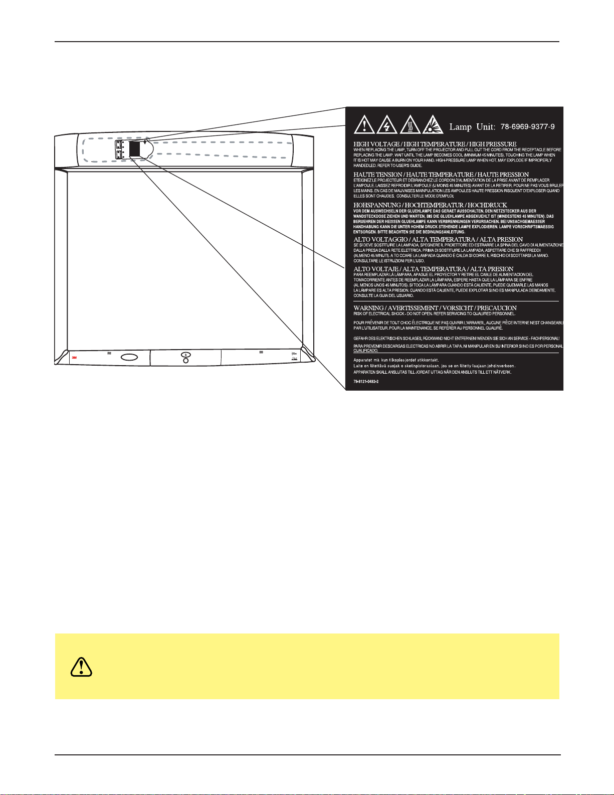
Model Identification and Differences
Identify Model
The nameplate, located behind the storage door, identifies the 3M Digital WallDisplay (DWD). Push the storage
door to open it. The figure below shows the nameplate, and the table shows the model numbers and corresponding model names.
Model Number
Model Number Model Name
8000DP 3M Digital WallDisplay 8000DP for Projection Display
8000VC 3M Digital WallDisplay 8000VC for Video Teleconferencing
8100CB 3M Digital WallDisplay 8100CB with Copyboard Display
8200IC 3M Digital WallDisplay 8200IC with Interactive Collaboration
8200IW 3M Digital WallDisplay 8200IW with Interactive Whiteboard
Model Differences
Below is a table that identifies the differences between the 3M Digital WallDisplay models.
Do not use markers, dry-erase or otherwise, on the 3M Digital WallDisplay
CAUTION
Model Number Projection Screen Copyboard* Interactive Whiteboard**
8000DP Easy Dry-Erase and NO NO
Projection
8000VC 3M Vikuiti High Brightness NO NO
for projection only
8100CB Easy Dry-Erase and YES NO
Projection
for Video Teleconferencing screen. Marks cannot be removed from the
3M Vikuiti High Brightness projection screen.
8200IW Easy Dry-Erase and NO YES
Projection
8200IC Standard Projection YES YES
and Dry-Erase
*The Copyboard feature allows you to print notes written on the 3M Digital WallDisplay to an attached
printer. (PCL3 compatible printer required. See list in Appendix.)
** The Digital Whiteboard feature allows you to capture notes written on the 3M Digital WallDisplay with
an attached computer or use the 3M Digital WallDisplay as an interactive display for a computer.
10
© 3M 2003. All Rights Reserved.
Page 11
3M™ Digital WallDisplay
POWER
R
MOUSE
MENU
INPUT
BLANK
MUTE
ON
OFF
1 2 3 4 5 6
Introduction
Contents
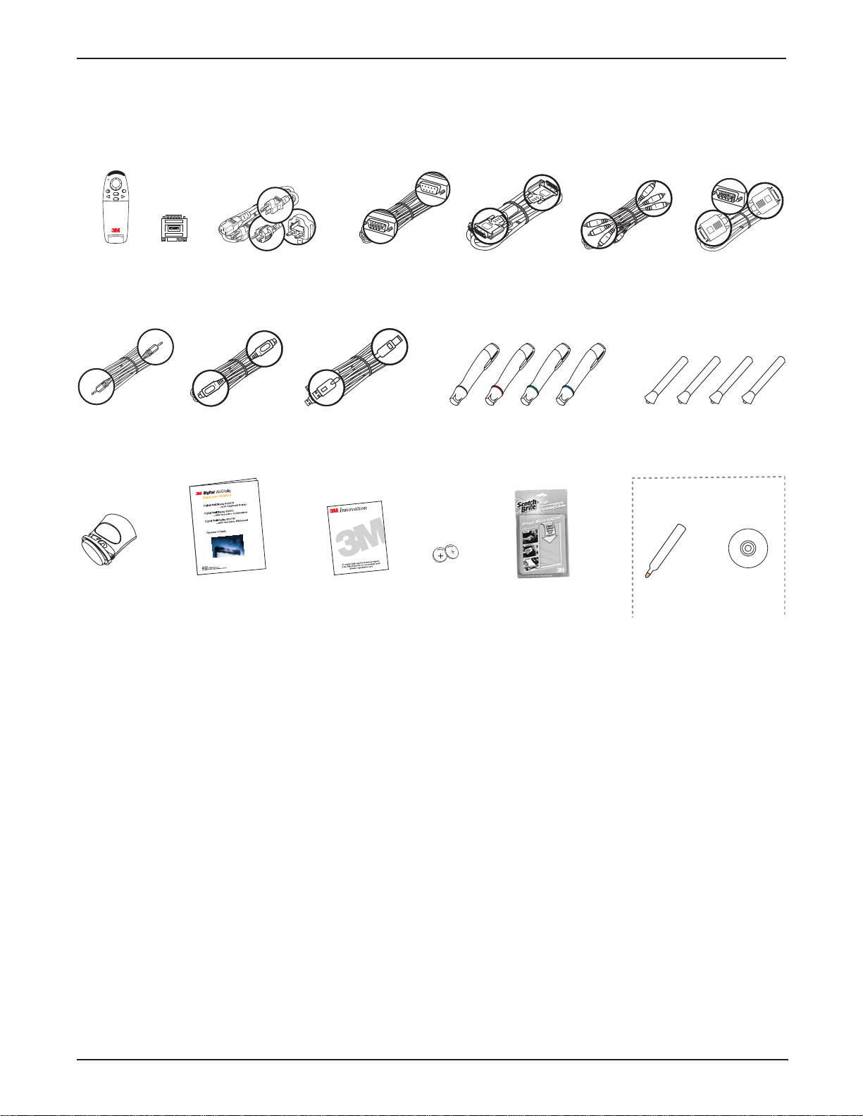
The 3M Digital WallDisplay (3M DWD) is shipped with the necessary cables required for standard VCR, PC,
Macintosh or laptop computer connections. Carefully unpack and verify that you have all of the items shown
below. If any are missing, please contact your place of purchase.
Remote
Control
Mac
adapter
Power Cable
(US, UK, Euro)
Serial Cable
DVI-D Cable
3-Conductor
Video/Audio Cable
VGA Cable
(with
batteries)
PC Audio Cable
S-Video Cable
USB Cable
4 Pen Sleeves
Dry-Erase Markers
3M DWD for 8200IC Only
Digital Eraser
Operator’s
Guide
Product
Registration
Card
Lithium Ion
Batteries
(10)
High-Performance
Cleaning Cloth
Digital Mouse
Stylus Insert
Software
CD-ROM
Optional Accessories
Note: Save the shipping box and packing materials in the event the 3M Digital WallDisplay should ever
• Accessory Tray/Laptop Shelf • Easy-Erase Screen
• Replacement Lamp Kit • Extended Warranty
• Screen
need to be moved.
What’s Next?
After the 3M Digital WallDisplay has been professionally installed in your meeting room, you are ready to set it
up.
Please read this guide thoroughly before operating your new 3M Digital WallDisplay.
Be sure to check our web site (www.3M.com/walldisplay) regularly for updates and supplemental information.
© 3M 2003. All Rights Reserved.
11
Page 12
12
Introduction
3M™ Digital WallDisplay
©3M 2003. All Rights Reserved.
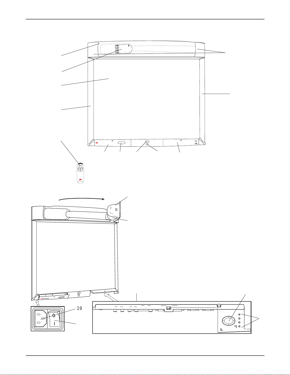
Part Identification
1
3
5
11
2
4
12
6
7 8 9
10
13
14
15
16
17
18
1. Facade
2. Lamp Housing Door (behind facade)
3. Projection Screen
4. Left Bezel
5. Remote Control Unit
6. Storage Door
7. Storage Door Window
8. On/Off Button
9. Infrared Remote Sensor
10. Connection Panel Door
11. Right Bezel
12. Speakers
13. Projection Head
14. Projection Arm
15. Connection Panel
16. Menu Keypad
17. Status LED Indicators
18. Master Power Switch
19. AC Power Cord Socket
19
POWERRMOUSE
MENU
MUTE
BLANK
INPUT
Wall Display
from 3M
PC
USB
AUDIO
MOUSE
1
2 (THIS ROW FOR DIGITAL WHITEBOARD OPTION ONLY) PRINTER COMPUTER
OUT
S-VIDEO RCA VGA DVI-D
IN
SERIAL
MOUSE
RS-232AUDIO VIDEO COMPUTERROW
1
2
3
MENU KEYPAD
4
Page 13

13
Introduction
3M™ Digital WallDisplay
©3M 2003. All Rights Reserved.
3M Digital Wall Display Features
The 3M Digital WallDisplay combines the following features into one sleek, sophisticated package.
• Full connectivity for computer or video presentations
• Large 60˝ diagonal screen
• 4:3 screen aspect ratio matches business applications and viewing data
•Flat screen allows extra wide (up to 170°) viewing angles
•Projection arm position guarantees image is in focus every time
•Allows presenter to move without blocking image
• Built-in, powerful stereo speaker system
• Single button operation
• Hand-held remote control for most functions
•Print your meeting notes directly to a PCL3-compatible printer
• 3M Digital WallDisplay for 8200IC and 8200IW unique features:
- Capture notes in color and save them in various file formats instantly (JPEG, GIF, TIFF, HTML,
PDF, vector PDF, EPS, BMP, WBD)
-Turn the 3M Digital WallDisplay into an interactive computer screen by using the virtual mouse
-Playback feature allows you to review all drawings on the board, including erased items
-Share meeting notes in real time anywhere in the world via the Internet
Page 14
14
3M™ Digital WallDisplay
©3M 2003. All Rights Reserved.
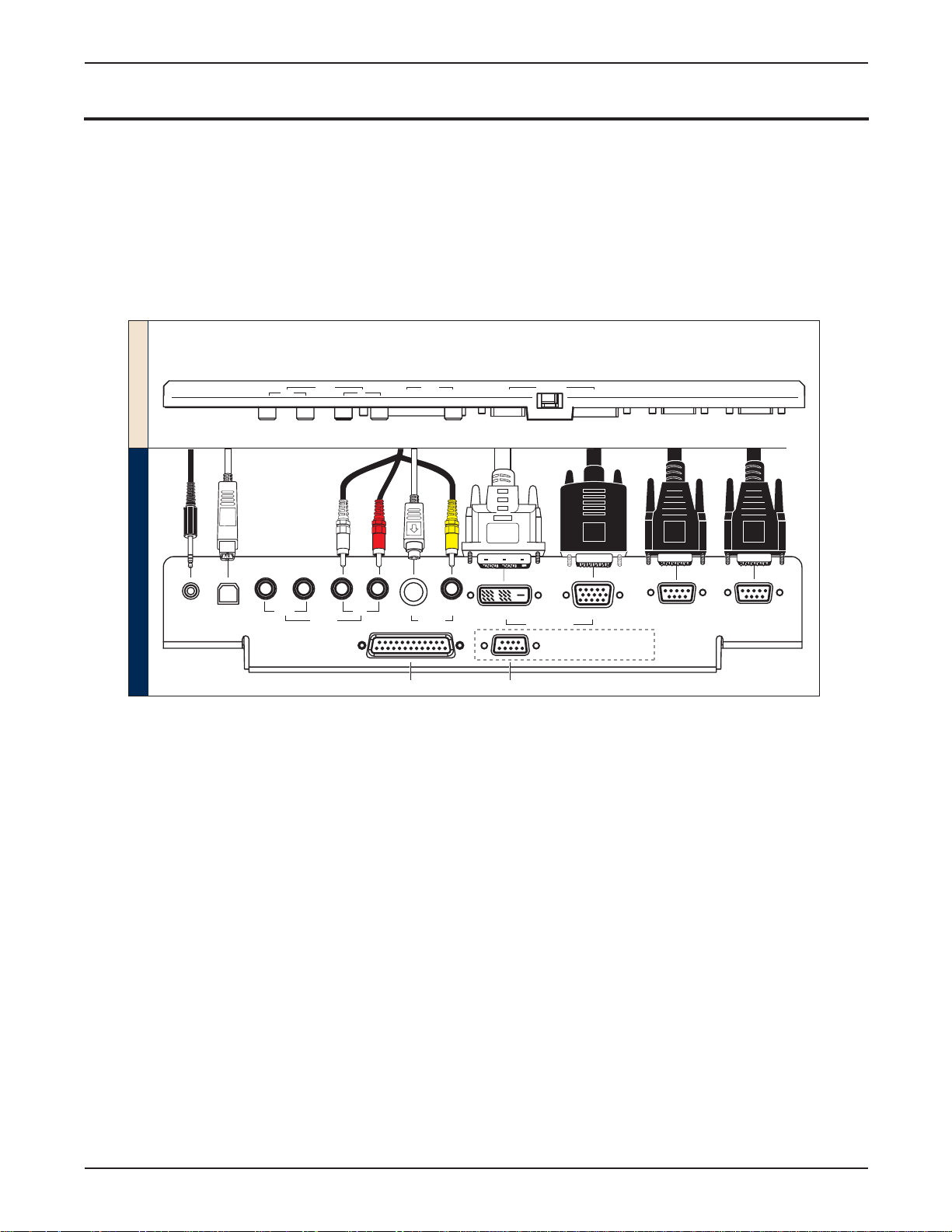
System Setup
Connecting to Various Equipment
It only takes a few minutes to connect the 3M Digital WallDisplay to your computer, VCR, DVD player, video
conference unit, or other devices.
The connection panel is located underneath the bottom right corner of the 3M Digital WallDisplay, under the
Connection Panel Door. Press and release door to access connection panel.
Note: Use the enclosed cables to ensure image and audio quality. Substituting cables of lesser quality may
result in poor image quality or audio noise.
PC Audio Connects to the computer’s audio output and provides audio for VGA and DVI-D
(Digital Visual Interface - Digital only) inputs.
USB Mouse Connects to the computer’s USB port and provides wireless mouse control using the 3M
Digital WallDisplay remote control
Disk Pad button.
Audio Out Connects to an external audio amplifier and provides audio from the active audio
source.
Audio In Connects to the audio output of a video device (e.g. VCR or DVD), and provides audio
for both S-Video and RCA video inputs.
S-Video Connects to an S-Video output signal.
RCA Video Connects to a composite video device.
DVI-D Connects to a computer that supports the DVI-D interface.
VGA Connects to the VGA or monitor Out port of a computer.
Serial Mouse Connects to a computer’s 9-pin serial port and provides wireless mouse control using
the 3M Digital WallDisplay remote control
Disk Pad button.
RS-232 Connects to a control device’s serial port and provides control of the 3M Digital
WallDisplay using RS-232C protocol and the specified serial commands.
*Available only on 3M DWD 8100CB and 8200IC
**Available only on 3M DWD 8200IC and 8200IW
3M DWD
with 8200IC
*
**
PC
AUDIO
1
2
(THIS ROW FOR DIGITAL WHITEBOARD OPTION ONLY
FRONT OF PANEL
BOTTOM OF PANEL
PC
Mouse
Audio
USB
MOU
USB
AUDIO
SE
OUT
)
Out S-Video RCA
Audio
I
N
In
VIDEO
S-VIDEO
Printer
RCA
PRINTERC
Video
OMPUTER
Computer
COMPUTE
RROW
VGADVI-D
Computer
VGADVI-D
(Whiteboard Display only)
SE
RIA
MOU
Serial
Mouse
L
SE
RS-
RS-232
232
Page 15
15
3M™ Digital WallDisplay
©3M 2003. All Rights Reserved.
Operation
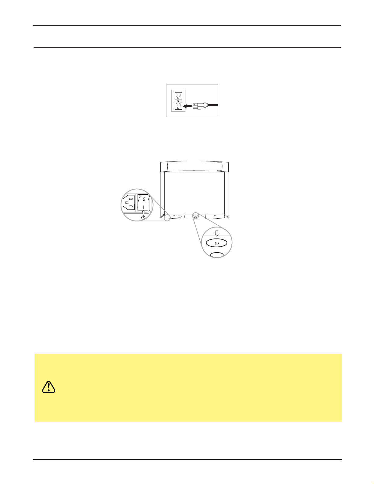
Startup
1. Plug power cord into wall socket.
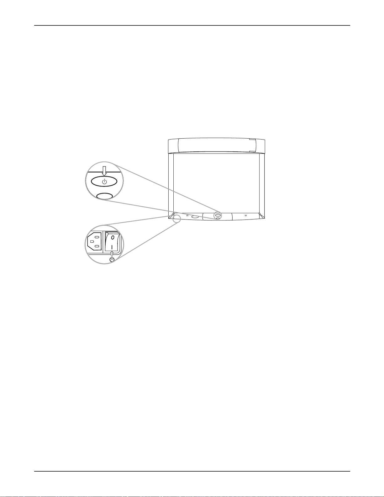
2. Flip on the
Master Power Switch beneath the lower left corner of the 3M Digital WallDisplay, near the
3M label. This should stay on at all times. Now the 3M Digital WallDisplay is in standby mode. The
large oval
On/Off Button will be backlit amber after several seconds.
3. Press the
On/Off Button in the center of the lower front panel. The projection arm will extend outward
from its housing at the top of the 3M Digital WallDisplay unit. Do not block its movement.
4. When the projection arm is fully extended, the lamp will turn on automatically. It will reach full illumina
tion in approximately 60 seconds. The
On/Off Button should then be backlit green.
CAUTION
• The 3M Digital WallDisplay’s projection arm is motorized. Do not block its
movement or force it to move while the 3M Digital WallDisplay is in
operation.
• Do not look directly into the 3M Digital WallDisplay projection lens. The
light from the lens may cause damage to eyes.
Page 16
16
Operation
3M™ Digital WallDisplay
©3M 2003. All Rights Reserved.
Shutdown
Press the On/Off Button on the bottom center panel of the 3M Digital WallDisplay unit.
The lamp will turn off and the projector arm will return to its housing. The
On/Off Button will flash amber as
the arm closes.
Note: There is a 30-second reset period before the On/Off Button will function again. During this period,
the On/Off Button will flash red.
The fan will continue to run for approximately five minutes to cool the unit.
Note: If the 3M Digital WallDisplay will not be moved or disconnected, leave the Master Power Switch on
for your convenience.
Do not turn off the
Master Power Switch or unplug the power cord before pressing the On/Off
Button.
After the On/Off Button is pressed, the fan continues for approximately five minutes to cool
the 3M Digital WallDisplay.
Page 17

17
3M™ Digital WallDisplay
©3M 2003. All Rights Reserved.
Remote Control Unit
Features
The remote control sensor is on the front lower panel of the 3M Digital WallDisplay unit. The distance between
the sensor and remote control must be shorter than 4 meters (13 feet).
The remote control unit has two keypads. The Forward keypad is above the flip-top cover. The Rear keypad is
beneath the cover. The
Trigger Button is underneath the front IR Sensor of the remote control unit and can be
pressed easily with the index finger.
IR SENSOR
Transmits infrared signals to 3M
Digital WallDisplay unit.
DISK PAD
Press to control the computer’s
mouse, navigate the menu
system, or control the Pointer or
Reveal functions.
R MOUSE
Press for right-mouse-button
function in mouse mode.
MENU
Press to display onscreen
menu system.
BLANK
Press to turn the screenblanking function on/off.
INPUT
Press to change source of
input.
VOLUME
Press to adjust the speaker
and Audio Out sound level.
TIMER
Press to turn on/off display of
countdown timer.
FREEZE
Press to turn the still-mode
function on/off.
REVEAL
Press to uncover part of the
screen from top to bottom or
from left to right.
LED
Indicates that remote control unit
is transmitting signal.
POWER
Press to turn 3M Digital
WallDisplay on/off.
MUTE
Press to turn the audio (speaker)
function on/off.
POINTER
Press to turn the pointing
function on/off.
FORWARD KEYPAD
REAR KEYPAD
TRIGGER BUTTON
Press for left-mouse
button functions.
POWER
MUTE
MENU
INPUT
POINTER
FREEZE
REVEAL TIMER
BLANK
VOLUME
R
MOUSE
+
Page 18

18
Remote Control Unit
3M™ Digital WallDisplay
©3M 2003. All Rights Reserved.
Forward Keypad
Power
Press to turn the 3M Digital WallDisplay on/off. When power is turned on, the 3M Digital WallDisplay will
automatically extend the projection arm and ignite the lamp.
Mute
Press to temporarily turn off the sound. Press again or press the Volume + or - buttons to restore sound.
Disk Pad
Press to:
• control the computer’s mouse when using the Mouse function.
• select menu items and adjust values in the onscreen menu system.
• control the Pointer position while using the Pointer function.
• control the path of the Reveal function.
While using the onscreen menu system or Pointer function, the computer Mouse function is temporarily disabled. To regain computer mouse control, turn off the current function or the onscreen menu system.
Note: The USB or serial mouse cable must be connected between the 3M Digital WallDisplay and the
computer when using Mouse mode.
R Mouse
Acts as the right-mouse-button when the mouse function is active.
Menu
Press to display the onscreen menu system or to cancel display.
Blank
Press to make the screen go blank. Press again to return to normal display function.
Input
Press to change the source of input for 3M Digital WallDisplay. The Input button cycles between Computer,
DVI, Composite Video (RCA jacks), and S-Video.
MENU
INPUT
R
MOUSE
BLANK
POWER
MUTE
Page 19

19
Remote Control Unit
3M™ Digital WallDisplay
©3M 2003. All Rights Reserved.
Rear Keypad
Pointer
Press to turn the pointing function on/off. A green dot will appear on the screen. The dot can be controlled by
pressing the arrows on the Disk Pad.
Volume
Press the + button to increase or the - button to decrease the speaker loudness level. When the audio is muted,
the
Volume + or - buttons will also cancel the Mute function.
Timer
Press to turn the timing function on/off. The timer will display on the screen and begin to count down. To change
the Timer value, refer to the
On Scrn Timer sub-menu in the Tools menu.
Freeze
Amoving image can be stilled or ‘frozen’ when the Freeze button is pressed. To release the Freeze function,
press the
Freeze button again.
Reveal
Press to turn the screen-reveal function on/off. Press the Disk Pad in the desired reveal direction (e.g. press
down to reveal from the top down, etc.).
Trigger Button
On the underside of the remote control unit, beneath the IR sensor, press button for left-mouse-button functions.
POWER
MUTE
MENU
INPUT
POINTER
VOLUME
FREEZE
REVEAL TIMER
R
MOUSE
BLANK
+
Page 20

20
Remote Control Unit
3M™ Digital WallDisplay
©3M 2003. All Rights Reserved.
Installing or Replacing Batteries
1. Push and slide the battery compartment tab in the direction shown, then lift it off.
2. Install two AAA batteries as indicated by the diagram inside the compartment.
3. Snap the battery compartment cover back on.
Note: Avoid excessive heat and humidity.
Do not mix old and new batteries or different types of batteries.
Page 21

21
3M™ Digital WallDisplay
©3M 2003. All Rights Reserved.
Digital Markers and Eraser
Assembling Digital Markers
The 3M Digital WallDisplay recognizes dry-erase marker writing by signalling the marker’s exact location to the
bezel. These signals are created and transmitted by small sensors near the ends of the battery-powered marker
sleeves.
To prepare the digital markers:
1. Unscrew the end cap on the marker sleeve, turning it counterclockwise. Insert two coin batteries
(CR2032), with the positive (+) side up. Screw the end cap back on, clockwise.
2. Press the ridged release button on the side of the marker sleeve, beneath the clip, to open the marker
compartment.
3. Remove the cap from a bullet-tip dry-erase marker. Be sure the marker color matches the color ring on
the marker sleeve. Insert the marker into the eBeam sleeve. Close the marker compartment.
Note: The eBeam Software detects the color of the marker sleeve, not the color of the marker inside it,
unless specifically changed. Normal pressure on the marker as you write on the 3M Digital
WallDisplay screen sends a “writing” signal in that sleeve’s designated color.
4. Cap the marker sleeve to keep the marker tip from drying out, just as you would with any other type of
marker. The cap also prevents sending signals when not in use.
5. Repeat steps 1 through 4 for all other marker sleeves.
Note: The signal transmitter in the digital sleeve is located just behind the tip of the marker. Grasp the sleeve
by the main barrel so your fingers will not block the signal.
CAUTION
These batteries contain lithium. Consult your local hazardous
waste regulations and dispose of these batteries in the proper
manner.
Page 22

22
Digital Markers and Eraser
3M™ Digital WallDisplay
©3M 2003. All Rights Reserved.
Assembling Digital Eraser
The digital eraser erases marker input by sending signals from the digital eraser in the same way as the digital
markers. The eraser sends an “erase” signal when you press the felt eraser against the 3M Digital WallDisplay
screen.
Remove the battery cover on the top of the digital eraser by twisting a coin counterclockwise in the slot. Insert
two coin batteries (CR2032), with the positive (+) side up. Screw the cover back on.
CAUTION
These batteries contain lithium. Consult your local hazardous
waste regulations and dispose of these batteries in the proper
manner.
Page 23

23
3M™ Digital WallDisplay
©3M 2003. All Rights Reserved.
Menu System
Menu Navigation
Most adjustments and settings are available in the main menu and sub-menus. To navigate and make adjustments,
use the 3M Digital WallDisplay’s Menu Keypad button or the remote control’s Menu and Disk Pad buttons.
Colorful—Bright Slider
The Colorful—Bright slider adjusts the brightness, contrast, and color saturation levels simultaneously. Move
the slider toward Colorful to achieve maximum color saturation and contrast. Move the slider toward Bright to
achieve maximum brightness.
To adjust the
Colorful—Bright slider:
1. Open the menu system by pressing the remote control
Menu button or any arrow on the Menu Keypad.
2. Select the
Colorful—Bright slider by pressing the up or down arrows on the remote control Disk Pad or
Menu Keypad.
3. Move the slider by pressing the left or right arrow of the
Disk Pad or Menu Keypad.
4. Close the menu system by pressing the
Menu button or scrolling to Exit and selecting it with the right
arrow of the Menu Keypad.
1
2
3
MENU KEYPAD
4
Page 24

24
Menu System
3M™ Digital WallDisplay
©3M 2003. All Rights Reserved.
Warm—Cool Slider
The Warm—Cool slider adjusts the color temperature. Move the slider toward Warm to achieve warmer, more
reddish images. Move the slider toward
Cool to achieve cooler, more bluish images.
To adjust the
Warm—Cool slider:
1. Open the menu system by pressing the remote control
Menu button or any arrow on the Menu Keypad.
2. Select the
Warm—Cool slider by pressing the up or down arrows on the remote control Disk Pad or
Menu Keypad.
3. Move the slider by pressing the left or right arrow of the
Disk Pad or Menu Keypad.
4. Close the menu system by pressing the
Menu button or scrolling to Exit and selecting it with the right
arrow of the
Menu Keypad.
Volume Slider
The Volume slider adjusts the speaker and audio output sound level. Move the slider toward the right to increase
the sound. Move the slider toward the left to decrease the sound.
To adjust the
Volume slider:
1. Open the menu system by pressing the remote control
Menu button or any arrow on the Menu Keypad.
2. Select the
Volume slider by pressing the up or down arrows on the remote control Disk Pad or Menu
Keypad
.
3. Move the slider by pressing the left or right arrow of the
Disk Pad or Menu Keypad.
4. Close the menu system by pressing the
Menu button or scrolling to Exit and selecting it with the right
arrow of the Menu Keypad.
Page 25

25
Menu System
3M™ Digital WallDisplay
©3M 2003. All Rights Reserved.
Mute Menu Function
The Mute menu function turns the sound on and off.
To turn the
Mute menu function on:
1. Open the menu system by pressing the remote control
Menu button or any arrow on the Menu Keypad.
2. Select the
Mute menu function by pressing the up or down arrows on the remote control Disk Pad or
Menu Keypad.
3. Turn the
Mute function on by pressing the left or right arrow of the Disk Pad or Menu Keypad. The
sound will turn off.
4. Close the menu system by pressing the
Menu button or scrolling to Exit and selecting it with the right
arrow of the
Menu Keypad.
To turn the
Mute menu function off:
1. Open the menu system by pressing the remote control
Menu button or any arrow on the Menu Keypad.
2. Select the
Mute menu function by pressing the up or down arrows on the remote control Disk Pad or
Menu Keypad.
3 Turn the
Mute function off by pressing the left or right arrow of the Disk Pad or Menu Keypad. The
sound will turn on.
4. Close the menu system by pressing the
Menu button or scrolling to Exit and selecting it with the right
arrow of the
Menu Keypad.
Mute function ON
Mute function OFF
Page 26

26
Menu System
3M™ Digital WallDisplay
©3M 2003. All Rights Reserved.
Input Select Menu
The Input Select menu defines the displayed video source. When Input Select menu is selected, the current
video source is shown. The
Input options are: Computer (VGA Input), DVI-D, S-Video, Comp. Video (RCA
Video Input), and No Signal. An Input option is available to select when an active video source is connected to
the 3M Digital WallDisplay input connection.
To set the
Input Select menu:
1. Open the menu system by pressing the remote control
Menu button or any arrow on the Menu Keypad.
2. Select the
Input Select menu function by pressing the up or down arrows on the remote control Disk Pad
or Menu Keypad.
3. Press the right arrow of the
Disk Pad or Menu Keypad repeatedly until the desired input option is shown.
4. Activate the input option by pressing the left arrow of the
Disk Pad or Menu Keypad.
5. Close the menu system by pressing the
Menu button or scrolling to Exit and selecting it with the right
arrow of the
Menu Keypad.
Reset All Menu
The Reset All menu function sets all menu settings to their default settings.
To turn the
Reset All menu function on:
1. Open the menu system by pressing the remote control
Menu button or any arrow on the Menu Keypad.
2. Select the
Reset All menu function by pressing the up or down arrows on the remote control Disk Pad or
Menu Keypad.
3. To activate the
Reset All function, press the right arrow of the Disk Pad or Menu Keypad .
4. Close the menu system by pressing the
Menu button or scrolling to Exit and selecting it with the right
arrow of the Menu Keypad.
Page 27

27
Menu System
3M™ Digital WallDisplay
©3M 2003. All Rights Reserved.
Image Adj Sub-Menu
The Image Adjustment sub-menu adjusts the projected image settings for the VGA and DVI-D inputs. Use the
Vertical Position and Horizontal Position sliders to reposition an image if portions are not visible. Use the
Phase and Sync sliders to eliminate vertical banding and noise.
Vertical Position Adjusts the vertical position of the projected image.
Horizontal Position Adjusts the horizontal position of the projected image.
Phase Adjusts the pixel sampling. Use this to reduce image noise and flicker.
Sync Adjusts the expected pixel number in a single video line. Use this to eliminate
banding.
Main Returns to main menu.
Exit Leaves the menu system.
To open the
Image Adj submenu:
1. Open the menu system by pressing the remote control
Menu button or any arrow on the Menu Keypad.
2. Select the
Image Adj sub-menu by pressing the up or down arrows on the remote control Disk Pad or
Menu Keypad.
3. To open the
Image Adj sub-menu, press the right arrow of the Disk Pad or Menu Keypad.
4. Scroll to the desired slider and move it to the right or left as needed.
5. Close the menu system by pressing the
Menu button or scrolling to Exit and selecting it with the left or
right arrow of the
Menu Keypad.
To return to the main menu, select
Main and press the left or right arrow of the Disk Pad or Menu Keypad.
Page 28

28
Menu System
3M™ Digital WallDisplay
©3M 2003. All Rights Reserved.
Tools Sub-Menu
The Tools sub-menu provides access to the following settings and tools:
Onscreen Timer Allows you to set a timer and display it onscreen.
Language Selects which language to use for onscreen commands. (Default language is
English.) It cycles between English, German, Spanish, Italian, and French.
Auto Shutoff Will automatically turn off the 3M Digital WallDisplay within the time desired.
(Default time is 0 minutes.)
Auto Switch When an input source is lost or disconnected, Auto Switch automatically detects
and switches to the next available input source. When Auto Switch is disabled,
press the
Input button on the remote control to select the next available input
source.
Usage/Hrs Displays and/or resets 3M Digital WallDisplay’s and lamp’s operating time, in
number of hours.
Audio Adjust Allows you to adjust the bass and treble.
To open the
Tools sub-menu:
1. Open the menu system by pressing the remote control
Menu button or any arrow on the Menu Keypad.
2. Select the
Tools sub-menu by pressing the up or down arrows on the remote control Disk Pad or Menu
Keypad.
3. To open the
Tools sub-menu, press the right arrow of the Disk Pad or Menu Keypad.
4. Scroll to the desired item and adjust as needed.
5. Close the menu system by pressing the
Menu button or scrolling to Exit and selecting it with the right
arrow of the Menu Keypad.
To return to the main menu, select
Main and press the left or right arrow of the Disk Pad or Menu Keypad.
Page 29

3M™ Digital WallDisplay
WallDisplay as a Copyboard or Digital
Whiteboard
Copyboard Mode
This mode lets the 3M Digital WallDisplay unit capture all the data from the screen and print it to a printer connected directly to the 3M Digital WallDisplay. No computer is needed to run this system. This mode should be
used without projection.
Note: 3M Classroom Display, 3M Briefing Display, and 3M Whiteboard Display are compatible only with the
PCL3 printers listed on Appendix page 50.
Whiteboard Mode (8200IC only)
You can use this mode without projection, to function as an electronic whiteboard. You can save, print to a PC or
networked printer (but not the printer connected to the 3M Digital WallDisplay), and share the meeting over a
network. It is not recommended to run projection in this mode because you will see the data from the projector
and the writing on the screen at the same time. The Print button on this system will work the same as the Print
command from the menu system, and the Clear button will start a new page.
Projection Mode (8200IC only)
The second way to use Whiteboard Display with a computer is in Projection mode. In this mode, your computer’s desktop is projected on the 3M Digital WallDisplay screen and the Whiteboard system can be used as a
touch screen. For this mode, use the Digital Mouse stylus insert instead of the dry-erase markers. The stylus is
used the same way a mouse is used on a PC (including the right-click function), but the Print and Clear buttons
will have no effect.
Using Copyboard Mode
Top LED Light Legend
NO DATA IN MEMORY
(No light)
BOARD IS RECEIVING DATA
MEMORY CONTAINS DATA
DATA IS PRINTING
CONNECTION ERROR
PRINTING ERROR
(Quickly blinking green)
(Slowly blinking green)
(Blinking with alternating
green and amber))
(Solid red)
(Slowly blinking red)
Printer Computer
1. Make sure the Master Power Switch is on and that the 3M Digital WallDisplay is plugged in.
The On/Off Button does not need to be turned on.
2. Use the digital markers to write on the board.
© 3M 2003. All Rights Reserved.
29
Page 30

WallDisplay as a Copyboard or Digital Whiteboard
3. Press the top bezel button to print.
4. Press the bottom bezel button to clear the page and any information stored in the buffer.
Using Whiteboard Mode
3M™ Digital WallDisplay
Top LED Light Legend
COMMUNICATING WITH A PC
(Solid amber)
CONNECTION ERROR
(Solid red)
Printer Computer
1. Plug in cables and insert markers into their digital sleeves.
2. On the attached computer, double-click the eBeam Software icon on the desktop to launch the program.
3. The top bezel button prints one copy of the active page to the default printer of the attached computer.
Note: Choose New Page to save your work before you erase the board.
4. The bottom bezel button clears the current page and displays a new blank page on your computer screen.
Installing eBeam Software on Your Computer
Minimum Requirements
The eBeam Software will run on any computers that meet these minimum criteria:
PC
• Microsoft
•Windows 98, 2000, ME, XP and Windows NT 4.0 compatible (other platform users may view shared
meetings via Java™ applet through Java-enabled Internet browser)
• 10 MB available hard drive space
• 256-color VGA or SVGA monitor
• CD-ROM drive or Internet connection for software installation
• One available serial port or USB port
®
Windows®compatible computer with Pentium® 100+ Mhz processor
Apple Macintosh
Although this help system does not discuss specific Macintosh help topics, there are versions of eBeam
Software for Macintosh computers that meet the following requirements:
• Power Macintosh
• Mac OS 9.x with Macintosh Runtime for Java™ 2.2 or higher and 64 MB RAM, or
• Mac OS X 10.1 or higher
• 10 MB available hard drive space
• One available USB port
30
© 3M 2003. All Rights Reserved.
Page 31

3M™ Digital WallDisplay
WallDisplay as a Copyboard or Digital Whiteboard
Installing the Software
Installing the eBeam Software for the 3M Digital WallDisplay is quick and easy. Just follow these steps below.
Install for PC Computer
1. Insert the CD labeled 3M Digital WallDisplay Software and Documentation into the PC’s CD-ROM
drive.
2. The CD will automatically display a menu.
3. Select the Install Software button to go to the Install Software menu.
4. Select the Install eBeam button to start the software installation program.
5. The software installation program will guide you through the installation process.
Install for Apple™ Macintosh Computer
1. Insert the CD labeled 3M Digital WallDisplay Software and Documentation into the CD-ROM drive of
the computer.
2. After CD icon appears on your desktop, double-click the CD icon to open it in Finder.
3. Open the folder labeled Software.
4. Open the folder that corresponds to the Mac OS version on the Apple computer.
5. Double-click the eBeam icon to start the installation program.
6. The software installation program will guide you through the installation process.
© 3M 2003. All Rights Reserved.
31
Page 32

WallDisplay as a Copyboard or Digital Whiteboard
Using Projection Mode
Top LED Light Legend
COMMUNICATING WITH A PC
(Solid amber)
CONNECTION ERROR
(Solid red)
3M™ Digital WallDisplay
VGA
Printer Computer
1. Turn on the 3M Digital WallDisplay unit and wait for image to appear on the screen.
2. Open a digital marker sleeve and slip the Digital Mouse Stylus into the sleeve, instead of a dry-erase
marker.
3. From the eBeam system tray menu, choose Use with Projector.
4. From the eBeam system tray menu, choose Calibrate Projection Area.
5. Follow all on-screen directions from the calibration wizard.
To learn more about the eBeam Software for the 3M Whiteboard, please refer to the eBeam Software for 3M
Whiteboard Display Operator’s Guide.
32
© 3M 2003. All Rights Reserved.
Page 33

33
3M™ Digital WallDisplay
©3M 2003. All Rights Reserved.
Maintenance
General Maintenance
For general cleaning of the screen and exterior of the 3M Digital WallDisplay, use a damp cloth or dry cleaning cloth such as the 3M High Performance Cleaning Cloth.
Standard dry-erase cleaners may be used on the dry-eraseable screens, such as Sanford
®
Expo®Whiteboard
Cleaner. Do not use other spray cleaners or solvents on any part of the 3M Digital WallDisplay.
Lamp Usage
Use and Replacement of Lamp
The 3M Digital WallDisplay lamp has a normal operating time of approximately 1600 hours, called the lamp
life. After the lamp has been operating for 1400 hours or longer, the following messages will appear on the
screen for the first three minutes of operation. When this happens, turn off the 3M Digital WallDisplay and
replace the lamp with a new one. Using an old lamp in the 3M Digital WallDisplay could cause a malfunction.
Onscreen Lamp Messages
PLEASE CHANGE THE LAMP
The lamp has been in use for 1400 hours and needs to be changed. After replacing the lamp, reset the lamp
timer.
THERE ARE (x) HOURS OF LAMP LIFE REMAINING
THE WALLDISPLAY WILL SHUT OFF IN 40 MINUTES
The lamp has been in use for 1500-1579 hours, and the power will turn off after 40 more minutes. After replacing the lamp, reset the lamp timer.
THERE ARE (x) HOURS OFLAMP LIFE REMAINING
THE WALLDISPLAY WILL SHUT OFF IN 5 MINUTES
The lamp has been in use for more than 1580 hours, and the power will automatically turn off after 5 minutes.
After replacing the lamp, reset the lamp timer.
All of these messages will display for no longer than three minutes, but each will display whenever you turn the
lamp on again, until the lamp is replaced.
For lamp-changing instructions, please refer to the next page.
Page 34

34
Maintenance
3M™ Digital WallDisplay
©3M 2003. All Rights Reserved.
Lamp Replacement
1. Turn the power off and disconnect the power cord from the outlet.
2. Allow approximately 45 minutes for the lamp to cool, if necessary.
3. There are two indentations behind the top of the facade, near
each end. Grasp facade plate at each indentation and pull out
and down to remove plate.
4. Loosen the self-contained screw at the upper righthand corner
of the lamp housing door with a standard screwdriver.
5. Two black wires connect to the lamp cartridge by a black
plastic receptacle on the right side of the lamp cartridge.
WARNING
To reduce the risk of electrical shock, always turn off the 3M Digital
WallDisplay unit and disconnect power cord before changing lamp.
Facade
Lamp
Receptacle
Black wires
Page 35

35
Maintenance
3M™ Digital WallDisplay
©3M 2003. All Rights Reserved.
5a. Hold down this receptacle with your left thumb and (5b) pull
connectors out of the receptacle with other hand.
6. Push up the metal lever on the lower left side of the lamp
cartridge.
7. Grasp the lamp cartridge and pull it straight back out of the
lamp compartment.
8. Keep the left edges of the new lamp cartridge aligned with
the lamp compartment’s grooves and slide the cartridge
smoothly into place.
Lever
5a
5b
Page 36

36
Maintenance
3M™ Digital WallDisplay
©3M 2003. All Rights Reserved.
9. Push down the metal lever on the left side of the lamp cartridge.
10. Reconnect black wires to the receptacle.
11.Close the lamp housing door and tighten the screw.
12. Align the slots and tabs of the right side of the facade and
projection arm as shown, then snap firmly into place.
13. Align the slots and tabs of the left side of the facade and
projection head as shown, then snap firmly into place.
Note: You must hear or feel a distinctive snap to ensure
facade is securely attached.
Whenever the lamp is replaced, please reset the total lamp operating time. (Refer to next page.)
CAUTION
•To reduce the risk of cuts to fingers and/or decreased image quality by
touching the lens, do not insert hand into the empty lamp compartment.
• This lamp contains mercury. Consult your local hazardous waste regulations
and dispose of this lamp properly.
•Apotential hazard may exist in the rare case of lamp rupture. Please have a
3M Digital WallDisplay dealer replace a ruptured lamp.
• The lamp is extremely hot during normal operation. Before replacing the lamp,
wait at least 45 minutes after last operation.
• Do not loosen any screws except those mentioned in the lamp replacement
instructions.
Page 37

37
Maintenance
3M™ Digital WallDisplay
©3M 2003. All Rights Reserved.
Resetting Lamp Hours
Please do the following within 10 minutes of turning power on after you replace the lamp.
1. Press the
Menu Keypad or the Menu button on the remote control and use the Disk Pad to scroll down
to the Tools menu.
2. In the
Tools menu, scroll down the pop-up list to Usage/Hrs to display the total operating time of the
lamp.
3. Select
Lamp Reset from the next pop-up list.
4. Select
Exit.
Note: Do not reset the lamp hours if the lamp cartridge was not changed. This can damage internal
components.
Page 38

38
Maintenance
3M™ Digital WallDisplay
©3M 2003. All Rights Reserved.
Replacing ProjectionScreen
Replacing the 3M Digital WallDisplay screen is very simple.
1. Turn off the 3M Digital WallDisplay and disconnect the power cord from the wall outlet.
2. Remove the right and left side bezels. There are two ways to remove it. Either snap it off or insert a
screwdriver into the notch located on the sides of each bezel, near the top. The bezel will easily snap on
and off for screen replacement.
3. Slide the screen straight out of the open side. Be sure to allow approximately 4 feet of clear space on
either side of the 3M Digital WallDisplay to do this.
4. Insert new screen into the open side and slide into place. Ensure that the screen is centered before
replacing the side bezels. The bezels have ribs on the inside that could damage the screen if it is not
centered.
5. Insert the bottom of the bezel first, then snap bezel back into place.
Page 39

39
3M™ Digital WallDisplay
©3M 2003. All Rights Reserved.
Troubleshooting
Common Problems and Solutions
Continued on next page
Symptom
Power cannot be
turned on.
No picture or
sound.
The lamp will not
ignite or has
turned off.
The projection
arm opens, then
closes.
Sound is heard
with no picture.
Picture is
displayed with no
sound.
Picture is dark.
Cause
The power cord is disconnected.
The Master Power Switch is not
turned on.
The arm facade is not in place.
The desired input source is not
selected.
The cables from the input source are
not connected.
The input source is not turned on or
not displaying an image. (e.g. If a
notebook computer, the external
monitor port is not turned on.)
The internal temperature is too high.
The lamp has reached maximum life or
has prematurely failed.
The lamp will not ignite.
The VGA/Video cables are not
connected.
The VGA/Video/Audio cables are
connected to the wrong input.
The VGA/Video cables are not
connected.
The audio cables are connected to the
wrong input.
The volume is set to Minimum.
The
Mute is on.
The
Colorful—Bright setting must be
adjusted.
The lamp needs to be replaced.
Solution
Insert the power cord into an AC
socket.
Turn on the Master Power Switch.
Make sure the arm facade is in
place.
Press the remote control Input
button to select a desired input
source.
Connect the cable to correct input
source.
Turn on input source.
Clear blocked ventilation holes.
Replace lamp.
Replace lamp.
Connect the cables to the correct
input source.
Connect the cables to the correct
input source.
Turn up
Volume.
Turn off
Mute.
Adjust Colorful—Bright slider
setting.
Replace lamp.
Page 40

40
Troubleshooting
3M™ Digital WallDisplay
©3M 2003. All Rights Reserved.
Common Problems and Solutions, continued
Onscreen Messages
Symptom
Desired input
source cannot be
detected.
The remote
control does not
work.
The menu system
will not display.
Cause
The input source is not active. Asignal
must be present for the input to be
selected.
The input device (e.g. computer, VHS
player, etc.) is not turned on.
The remote control is not facing the
remote control sensor.
The remote control is too far from the
sensor.
An obstruction is between the remote
control and the sensor.
The remote control’s batteries are
exhausted.
The menu system will not display
without an input source displayed.
Solution
Connect an active input source to
unit.
Turn on input source.
Face the remote control toward the
remote control sensor.
Operate the remote control within 5
meters.
Remove obstacle.
Replace batteries.
Connect an active input source to
unit.
Message
No input is detected
Please change the lamp
There are (x) hours of lamp life remaining
The WallDisplay will shut off in 40 minutes
There are (x) hours of lamp life remaining
The WallDisplay will shut off in 5 minutes
Meaning
3M Digital WallDisplay is not receiving a signal
from an external source. Check the cable
connections and verify power is on and external
source is working.
The lamp has 1400-1499 hours on it and needs
to be changed.
The lamp has 1500-1579 hours on it and needs
to be changed.
When the lamp has 1580 hours or more on it,
the message will flash, and the power will turn
off after 5 minutes.
Page 41

41
Troubleshooting
3M™ Digital WallDisplay
©3M 2003. All Rights Reserved.
eBeam Software
Troubleshooting provides solutions for known issues with the eBeam system. This section covers
the Microsoft®Windows®versions of eBeam Software.
eBeam Hardware Detection/Use
Message
“eBeam not found.
Check connection
cable and power
supply.”
(This message might
appear at application
startup, or during the
course of a meeting.)
Status Line Message.
“Could not autodetect
eBeam Hardware.” or
“Could not connect to
eBeam Hardware on
X.” (where X is a port)
(This message would
most likely occur
when you have
selected
Cancel from
the eBeam not found
message dialog box.)
“The eBeam hardware is currently used
by Projection mode.
Would you like to use
the eBeam hardware
for this application?”
(This message might
appear at application
startup or after selecting
Whiteboard
Mode.)
eBeam
Software
Software
Software
Try the following:
•First check the hardware for your system as described,
and then click Cancel.
• See Unable to Detect the Hardware.
• Do you have more than one copy of eBeam Software
installed on your computer? If so, the other copy may be
running and have control of the port. Shut down the
other copy. We recommend that old versions of eBeam
Software be uninstalled from your computer.
• Exit the eBeam Software’s Meeting application and
restart it.
• Check that the eraser is not resting on the eraser pad.
• If you are using a Serial-to-USB connector, follow the
manufacturer’s setup instructions.
• See
“eBeam not found.” Check connection cable and
power supply. (This message might appear at application startup or during the course of a meeting.)
• See Unable to Detect the Hardware.
• Message displayed if you are trying to open or switch to
eBeam Software’s Meeting application from Projection
mode.
Page 42

42
Troubleshooting
3M™ Digital WallDisplay
©3M 2003. All Rights Reserved.
Network Connection/Shared Meetings
Problem
To share a meeting,
the eBeam Hardware
must be connected
and detected.”
(This message
appears when you
choose
Shared
Meeting.)
Unable to share or
join a meeting over
the EFI meeting
server.
Using a cable modem
or DSL and unable to
share or join a meeting over the EFI meeting server.
Unable to see shared
meeting names in the
Join Meeting dialog
box.
How to set up the
proxy server?
eBeam
Software
Software
Software
Software
Software
Try the following:
•To serve as the meeting host, your computer must be
attached to the eBeam Hardware. See
Hosting/Sharing
a Meeting.
• If you are attempting to share a meeting, make sure that
you have the eBeam Hardware connected. See
Hosting/Sharing a Meeting.
• If your network/Internet connection is behind a firewall or
proxy server, you will have to set up the proxy server.
See Proxy Server Setup.
• If you are attempting to share a meeting, make sure that
you have the eBeam Hardware connected. See
Hosting/Sharing a Meeting.
• If your network/Internet connection is behind a firewall or
proxy server, you will have to set up the proxy server.
See
Proxy Server Setup.
Even if you think you aren’t behind a proxy server/firewall, you
might be. Your ISP might have a firewall set up, causing this
problem. Try:
• Add a new server (see
Adding a Meeting Server) with
a DNS: meetings.e-beam.com, and port: 443.
• This option is only available in version 2.1 and later.
Newer versions of the software automatically attempt to
connect through port 443, but it may be necessary to
manually set up the server as described previously.
• When the meeting host shares the meeting through the
Share Meeting dialog box (see Hosting/Sharing a
Meeting
), they can select whether or not to publish the
meeting name. if the meeting name is published, then it
will show up in the Join Meeting dialog box. if the meet
ing name is not published, then other meeting partici
pants must manually type the meeting name into the
meeting name text box.
•To publish the meeting name, make sure that the
Publish meeting name check box in the Share
Meeting dialog box is checked.
• Does your intranet have a proxy server/firewall? Most
intranets do. If you have not done so, enable your proxy
server. See
Proxy Server Setup.
• See Proxy Server Setup.
Page 43

43
Troubleshooting
3M™ Digital WallDisplay
©3M 2003. All Rights Reserved.
Problem
Software states that
the eBeam hardware
is detected, but writing does not appear
in eBeam Software’s
Meeting application
Active Page.
Software is missing
many of the strokes
written with the digital
marker.
Digital marker strokes
are shown in eBeam
Software’s Meeting
application in the
wrong color.
Digital marker strokes
made at the bottom of
the whiteboard do not
appear in eBeam
Software’s Meeting
application.
eBeam
Hardware
Software
Hardware
Hardware
Software
Hardware
Try the following:
•Press the digital marker down on the whiteboard. If you
do not hear a faint buzzing, replace the batteries.
•Try another digital marker. If the other digital marker
works, replace the batteries in the digital marker sleeve
that does not work.
• Make sure you are not holding the sleeve too close to
the tip of the digital marker. This blocks the signal.
• Choose
eBeam Hardware > Detect eBeam Hardware
from the eBeam Software’s Meeting application Tools
menu and then check the status line. If it states that the
hardware is not detected, see Manually Detecting the
eBeam Hardware
.
•Press the digital marker down on the whiteboard. If you
do not hear a faint buzzing, replace the batteries.
• Make sure you are not holding the sleeve too close to
the tip of the digital marker. This blocks the signal.
• Make sure that you are pressing the digital marker firmly
against the 3M Digital WallDisplay when you write. The
marker is designed to write with a normal amount of
pressure by the writer; however, it is possible to write so
softly that the marker does not send out a signal.
• Make sure you are using the correct color digital marker
sleeve. The color of the digital marker sleeve is shown
on a color ring located near the tip of the digital marker.
• Check the color set for the sleeve in the Sleeve Settings
dialog box (see Setting Pen Colors/Line Thickness). It
is possible to set a different color in the software for any
eBeam digital marker.
•Press the digital marker down firmly on the whiteboard.
If you do not hear a faint buzzing noise, replace the batteries.
•Make sure you are not holding the digital marker too
close to the tip. This blocks the signal.
• Make sure that you are pressing the marker firmly
against the whiteboard when you write. The marker was
designed to write with a normal amount of pressure by
the writer; however, it is possible to write so softly that
the marker does not send out a signal.
Writing Data/Capture
Continued on next page
Page 44

44
Troubleshooting
3M™ Digital WallDisplay
©3M 2003. All Rights Reserved.
Problem
Digital marker strokes
made at the bottom of
the whiteboard do not
appear in eBeam
Software’s Meeting
application.
Digital eraser does
not erase.
eBeam
Software
Software
Try the following:
•Make sure you are writing within the calibrated image
area on the whiteboard.
•Press the eraser down on the whiteboard. If you do not
hear a faint buzzing noise, replace the batteries.
• Choose
eBeam Hardware > Detect eBeam Hardware
from the eBeam Software’s Meeting application Tools
menu and then check the status line.
Writing Data/Capture, continued
Page 45

45
Troubleshooting
3M™ Digital WallDisplay
©3M 2003. All Rights Reserved.
Problem
Applet does not load.
While using iVISTA,
the applet does not
load.
Unable to see shared
meeting names in the
Join Meeting dialog
box.
eBeam
Software
Software
Software
Try the following:
Microsoft
®
Internet Explorer
®
•In Internet Explorer, go to Tools > Internet Options.
Click the
Security tab, and then click Restricted Sites.
Click the Custom Level button, and then scroll down
the list to Microsoft VM. Make sure that Disable Java
is not selected. Attempt to open the applet again.
•In Internet Explorer, go to
Tools > Internet Options,
and click the Delete Files button. Attempt to open the
applet.
Netscape
®
• In Netscape, go to File (or Edit) > Preferences. Click
the Advanced option, and make sure that Enable Java
is checked.
• In Netscape, go to
File (or Edit) > Preferences. Click
the Advanced option, and then click Cache Click both
the Clear Memory Cache and Clear Disk Cache
buttons. Attempt to reopen the applet.
iVISTA and eBeam Software’s Meeting application both use
port 80 as the default connection port. Try hosting the eBeam
meeting over port 81 or some other port value. Try:
•From the
Share Meeting dialog box (see
Hosting/Sharing a Meeting), select Use my PC to
host this meeting
, then type 81 in the Port text box.
• Participants attempting to log in to the meeting should
type http://meeting_name:81, where meeting_name is
the name entered in the Meeting Name text box, and 81
is the port value you have entered.
• When the meeting host shares the meeting through the
Share Meeting dialog box (see Hosting/Sharing a
Meeting), they can select whether to publish the meet-
ing name. If the meeting name is published, it will show
up in the Join Meeting dialog box. If the meeting name
is not published, then other meeting participants must
manually type the meeting name into the
Meeting Name
text box.
•To publish the meeting name, make sure that the meet
ing host checked the
Publish Meeting Name check box
in the Share Meeting dialog box.
• Does your intranet have a proxy server/firewall? Most
intranets do. If you have not done so, enable your proxy
server. See
Proxy Server Setup.
EFI Meeting Applet
Page 46

46
Troubleshooting
3M™ Digital WallDisplay
©3M 2003. All Rights Reserved.
Problem
Microsoft ®Excel
®
spreadsheet did not
load properly.
Background image
quality is bad.
eBeam
Software
Software
Try the following:
• Is there a graph in the spreadsheet? eBeam Software’s
Meeting application cannot import a spreadsheet
containing a graph.
• See
Loading an Excel Spreadsheet as a Background
Image.
• Background images that are sent to the applet meeting
viewer are highly compressed to make the image faster
to download. Using the eBeam Software’s Meeting application is better if you wish for background images to be
easy to view.
Background Images
Page 47

47
3M™ Digital WallDisplay
©3M 2003. All Rights Reserved.
Service Information
Parts and Accessories
Description Part Number
Power Cord (EU) 78-8131-0004-3
Power Cord (US) 78-8131-0005-0
Power Cord (UK) 78-8131-0003-5
Serial Mouse Cable 26-1015-0423-6
USB Cable 26-1015-0424-4
VGA Cable 26-1015-0425-1
DVI-D Cable 26-1015-0418-6
PC Audio Cable 26-1015-0420-2
S-Video Cable 26-1015-0422-8
Replacement Lamp Kit 78-6969-9377-9
Remote Control Unit 78-8121-0330-3
Macintosh Adapter 26-1015-0419-4
3-Conductor Video/Audio Cable 26-1015-0421-0
Dry-Erase Screen 78-6969-9470-2
3M Vikuiti High Brightness Screen 78-6969-9471-0
Optional Accessories
Accessory Tray (right) 78-6969-9371-2
Accessory Tray (left) 78-6969-9472-8
Easy Erase Screen 78-6969-9469-4
Ordering Parts or Getting Information
For product information, product assistance, service information, or to order accessories, please contact 3M
Customer Service at the following numbers:
• In U.S. or Canada:
1-800-328-1371
• In other locations, contact your 3M Sales office.
The contents of this manual are subject to change without prior notice.
3M assumes no responsibility for the infringement of special rights of a third party or other rights that may arise out of the
information contained in this manual.
Reproduction of this manual in any form without prior permission is strictly prohibited.
Page 48

48
3M™ Digital WallDisplay
©3M 2003. All Rights Reserved.
Appendix
3M™ Digital WallDisplay Specifications
1600 hours
20 Watts per channel
eziSyalpsiDaeraelbaweivlanogaiD˝06
oitaRtcepsAyalpsiD3:4
metsySyalpsiD ygolonhcetstnemurtsnIsaxeT™PLD,pihCelgniS
eziSlanogaiDpihChcni7.0
pihCPLD
slexiPforebmuNslexip867x4201
roloCroloclluftib-42
oitaRtsartnoC1:051
epyT)erusserPhgiH-repuS(PHS
pmaL
efiLsruoH0002
snoisnemiD
thgieW.sbl58.xorppA
ytilibitapmoCoediV MACES,M-LAP,N-LAP,LAP,34.4CSTN,CSTN
ytilibitapmoCoediVretupmoCAGXSotAGV
noitalumEesuoM BSUdna,BDA,esuomlairesCP
tupnIretupmoC
slangiS
tuptuO/tupnI
lanimreT
tuOoiduAskcajACR
metsySoiduA
srekaepSsmhO8,xaMsttaW04
slangistupnioediVnip-4NIDiniM:oediV-S
troPlortnoC232-SRbuS-Dnip-9
troPnoitalumEesuoMbuS-Dnip-9
)srekaepsot(reifilpmAlennahcrepttaW81
D˝0.7xW˝2.35xH˝6.74
)mm971xmm0531xmm8021(
buS-Dinimnip-51:BGRgolanA
)ylnolatigid(D-IVD:BGRlatigiD
kcaj-inimoeretsmm5.3:oiduA
stnemeriuqeRrewoP .xaMsttaW004,zH06/05,CAV042~001
Page 49

3M™ Digital WallDisplay
Input/Output Signal Specifications
Appendix
langiSoediV
langiScnySlatnoziroH
retupmoC
oediV-S
oediV
langiSoediVsmhO57,p-pV0.1
langiScnySlacitreV
langiScnySetisopmoCleveLLTT
langiStupnIoiduA
langiStuptuOoiduAsmhOk1,smrVm002~0
langiStupnIoiduAsmhOk02,smrVm002
)ytiralop
)ytiralop
)p-pV0.3
smhO57
smhO
smhO57,p-pV7.0golanA
)ytiralopevitisop(noitanimret
evitagen/evitisop(leveLLTT
evitagen/evitisop(leveLLTT
xaM(smhOk02,smrVm002
,p-pV0.1:langisecnanimuL
:langisecnanimorhC
57,)tsrubroloc(p-pV682.0
Computer Compatibility
Resolution Refresh Rate Horizontal
640x400 85 Hz 37.9 kHz
640x480 60 Hz 31.5 kHz
640x480 72 Hz 37.9 kHz
640x480 75 Hz 37.5 kHz
640x480 85 Hz 43.3 kHz
800x600 56 Hz 35.1 kHz
800x600 60 Hz 37.9 kHz
800x600 72 Hz 48.1 kHz
800x600 75 Hz 46.9 kHz
800x600 85 Hz 53.7 kHz
1024x768 60 Hz 48.4 kHz
1024x768 70 Hz 56.5 kHz
1024x768 75 Hz 60.0 kHz
1024x768 85 Hz 68.7 kHz
1280x1024 60 Hz 64.0 kHz
Frequency
© 3M 2003. All Rights Reserved.
49
Page 50

50
Appendix
3M™ Digital WallDisplay
©3M 2003. All Rights Reserved.
Printer Compatibility
Apollo P-2200 HP LaserJet 1100
1120
Fiery X2e 4050
4500
HP Business Inkjet 2250TN 4L
4M Plus
HP Color LaserJet 4550 5000
5L
HP DeskJet 340 5si
350 6MP
400 8100
420 8150
500 IIID
540
600 HP OfficeJet 590
610 630
630 685
648 G55
648C G85
694 K60
840 K80
842 R65
842C T45
880 Pro 1175CSE
895
932 HP PhotoSmart 1215
932C
940
950
952C
960 HP PSC 500
970
970 Cse Hitachi DDS 50/62
990
990 Cse Konica 7040
1120
1125
1220
1220C
1218
P1000
P1100
Page 51

51
Section Head
3M™ Digital WallDisplay
©3M 2003. All Rights Reserved.
(This page intentionally left blank for printed version)
Page 52

Important Notice
All statements, technical information, and recommendations related to 3M’s products are based on information believed to be
reliable, but the accuracy or completeness is not guaranteed. Before using this product, you must evaluate it and determine if it
is suitable for your intended application. You assume all risks and liability associated with such use. Any statements related to
the product which are not contained in 3M’s current publications, or any contrary statements contained on your purchase order
shall have no force or effect unless expressly set forth in a written agreement signed by an authorized officer of 3M.
Avis Important
Toutes les déclarations, l’information d’ordre technique et les recommendations afférentes aux produits 3M sont fondées sur
des renseignements supposés exacts, mais la précision ou l’intégralité n’est pas garantie. Avant d’utiliser ce produit, vous devez
l’évaluer afin de déterminer s’il est adapté aux applications que vous avez l’intention d’utiliser. Vous acceptez tous les risques
et la responsabilité associés à une telle utilisation. Toutes les déclarations concernant le produit qui ne sont pas incluses dans
les publications actuelles de 3M et toutes les déclarations contradictoires qui sont incluses sur votre bon de commande seront
sans effet sauf accord explicite par écrit avec un cadre agréé de 3M.
Wichtiger Hinweis
Alle Angaben, technischen Informationen und Empfehlungen, die sich auf 3M-Produkte beziehen, sind nach bestem Wissen
korrekt und zuverlässig, jedoch können wir keine Gewähr übernehmen. Vor der Anschaffung dieses Produkts sollten Sie sich
davon überzeugen, das es für den vorgesehenen Einsatz tauglich ist. Alle aus der Verwendung des Produkts entstehenden
Risiken und jegliche Haftung liegt bei Ihnen. Jegliche sich auf das Produkt beziehende Aussagen, die nicht aus einer aktuellen
Veröffentlichung von 3M stammen bzw. jegliche im Kaufauftrag enthaltene gegensätzliche Aussagen sind ohne ausdrückliche
schriftliche Genehmigung durch einen autorisierten Vertreter von 3M nicht gültig bzw. ohne Wirkung.
Aviso Importante
Todas las declaraciones, información técnica y recomendaciones relacionadas con los productos 3M está basada en información que se cree fiable, pero la preción o lo completo de éstas no está garantizado. Antes de utilizar este producto debe evaluarlo y determinar si es adecuado para su aplicación. Usted asume todos los riesgos y la responsabilidades asociadas con dicho
uso. Cualquier afirmación relacionada con el producto que no se encuentre en las publicaciones actuales de 3M, o cualquier
afirmación contraria incluida en su orden de compra, carecerá de vigencia y efecto si no ha sido acordada expresamente, por
escrito, por un funcionario autorizado de 3M.
Avviso importante
Tutte le dichiarazioni, le informazioni tecniche e i consigli relativi a prodotti 3M si basano su informazioni ritenute affidabili,
ma la loro accuratezza o completezza non sono garantite. Prima di utilizzare questo prodotto, è necessario valutarlo e determinarne l’idoneità per l’applicazione prevista. L’utente si assume tutti i rischi e le responsabilità associati a tale utilizzo. Qualsiasi
dichiarazione relativa al prodotto che non sia riportata nelle pubblicazioni correnti della 3M o qualsiasi dichiarazione opposta
riportata sull’ordine d’acquisto, non costituirà obbligo e non avrà alcun effetto, tranne se concordato esplicitamente con autorizzazione scritta emessa da un rappresentante ufficiale della 3M.
Litho in USA
Copyright © 2003 3M
All Rights Reserved
78-6970-9185-4 Rev. A
3M Austin Center
Building A145-5N-01
6801 River Place Blvd.
Austin, TX 78726-9000
3M Canada
P.O. Box 5757
London, Ontario
N6A 4T1
3M Mexico, S.A. de C.V.
Apartado Postal 14-139
Mexico, D.F. 07000
Mexico
http://www.3M.com/walldisplay
3M Europe
Boulevard de l’Oise
95006 Cerge Pontoise Cedex
France
Copyright © 2002 3M
All Rights Reserved
78-6970-9074-0 Rev. C
Litho in USA
 Loading...