

Page 1

2802x C/C++ Header Files and Peripheral Examples Quick Start
Version 1.25
December 18, 2009
SPRC992
2802x C/C++ Header Files and Peripheral Examples
Quick Start
1 Device Support:............................................................................................................................ 2
2 Introduction: ................................................................................................................................. 2
2.1 Revision History...................................................................................................................... 3
2.2 Where Files are Located (Directory Structure) ........................................................................ 4
3 Understanding The Peripheral Bit-Field Structure Approach ................................................... 6
4 Peripheral Example Projects ....................................................................................................... 7
4.1 Getting Started ....................................................................................................................... 7
4.1.1 Getting Started in Code Composer Studio v4.0+......................................................... 7
4.2 Example Program Structure.................................................................................................. 13
4.2.1 Source Code............................................................................................................. 14
4.2.2 Linker Command Files .............................................................................................. 14
4.3 Example Program Flow......................................................................................................... 16
4.4 Included Examples: .............................................................................................................. 17
4.5 Executing the Examples From Flash..................................................................................... 19
5 Steps for Incorporating the Header Files and Sample Code ................................................... 23
5.1 Before you begin................................................................................................................... 23
5.2 Including the DSP2802x Peripheral Header Files ................................................................. 23
5.3 Including Common Example Code........................................................................................ 27
6 Troubleshooting Tips & Frequently Asked Questions............................................................. 30
6.1 Effects of read-modify-write instructions. .............................................................................. 32
6.1.1 Registers with multiple flag bits in which writing a 1 clears that flag........................... 33
6.1.2 Registers with Volatile Bits........................................................................................ 33
7 Migration Tips for moving from the TMS320x280x or TMS320x281x header files to the
TMS320x2802x header files ....................................................................................................... 34
8 Packet Contents:........................................................................................................................ 35
8.1 Header File Support – DSP2802x_headers.......................................................................... 35
8.1.1 DSP2802x Header Files – Main Files........................................................................ 35
8.1.2 DSP2802x Header Files – Peripheral Bit-Field and Register Structure Definition
Files .......................................................................................................................... 36
8.1.3 Variable Names and Data Sections........................................................................... 37
8.2 Common Example Code – DSP2802x_common................................................................... 38
8.2.1 Peripheral Interrupt Expansion (PIE) Block Support .................................................. 38
8.2.2 Peripheral Specific Files............................................................................................ 39
8.2.3 Utility Function Source Files...................................................................................... 40
8.2.4 Example Linker .cmd files ......................................................................................... 40
8.2.5 Example Library .lib Files .......................................................................................... 41
9 Detailed Revision History: ......................................................................................................... 42
1
Page 2

V1.25 Quick Start Readme
1 Device Support:
This software package supports 2802x devices. This includes the following: TMS320F28027,
TMS320F28026, TMS320F28023, TMS320F28022, TMS320F28021, TMS320F28020, and
TMS320F280200.
Throughout this document, TMS320F28027, TMS320F28026, TMS320F28023,
TMS320F28022, TMS320F28021, TMS320F28020, and TMS320F280200 are abbreviated as
F28027, F28026, F28023, F28022, F28021, F28020, and F280200 respectively.
2 Introduction:
The 2802x C/C++ peripheral header files and example projects facilitate writing in C/C++
Code for the Texas Instruments TMS320x2802x DSPs. The code can be used as a learning
tool or as the basis for a development platform depending on the current needs of the user.
• Learning Tool:
This download includes several example Code Composer Studio™† v4.0+ projects for a
‘2802x development platform.
These examples demonstrate the steps required to initialize the device and utilize the onchip peripherals. The provided examples can be copied and modified giving the user a
platform to quickly experiment with different peripheral configurations.
These projects can also be migrated to other devices by simply changing the memory
allocation in the linker command file.
• Development Platform:
The peripheral header files can easily be incorporated into a new or existing project to
provide a platform for accessing the on-chip peripherals using C or C++ code. In
addition, the user can pick and choose functions from the provided code samples as
needed and discard the rest.
To get started this document provides the following information:
• Overview of the bit-field structure approach used in the 2802x C/C++ peripheral header
files.
• Overview of the included peripheral example projects.
• Steps for integrating the peripheral header files into a new or existing project.
• Troubleshooting tips and frequently asked questions.
• Migration tips for users moving from the DSP280x header files to the DSP2802x header
files.
†
Code Composer Studio is a trademark of Texas Instruments (www.ti.com).
2
Page 3

Finally, this document does not provide a tutorial on writing C code, using Code Composer
Studio, or the C28x Compiler and Assembler. It is assumed that the reader already has a
2802x hardware platform setup and connected to a host with Code Composer Studio
installed. The user should have a basic understanding of how to use Code Composer Studio
to download code through JTAG and perform basic debug operations.
2.1 Revision History
Version 1.25
This version includes minor corrections to the header files and examples. The most
notable change is that gel files and cmd linker files for the 280200 devices now
include 1K additional L0 RAM. A detailed revision history can be found in Section 9.
Version 1.21b
This version update only updates the V1.21 Quick Start Readme to adjust wording for
the controlSUITE software package. No changes to the header file and peripheral
example code were made.
Version 1.21
V1.25 Quick Start Readme
This version includes minor corrections and comment fixes to the header files and
examples. A detailed revision history can be found in Section 9.
Version 1.20
This version includes corrections and comment fixes to the header files and examples.
It adds examples pertaining to the ADC temperature sensor and compensation of the
oscillator frequency over temperature, and it also fixes an error in the
SFO_TI_Build_V6.lib library in the new SFO_TI_Build_V6b.lib library . A detailed
revision history can be found in Section 9.
Version 1.10
This version includes corrections and comment fixes to the header files and examples,
adds 3 new 2802x devices – 28021, 28020, and 280200 - , deletes 2 2802x devices –
28024 and 28025 - and also adds a separate example folder,
DSP2802x_examples_ccsv4, with examples supported by the Eclipse-based Code
Composer Studio v4. A detailed revision history can be found in Section 9.
Version 1.00
This version is the first release of the 2802x header files and examples.
3
Page 4
V1.25 Quick Start Readme
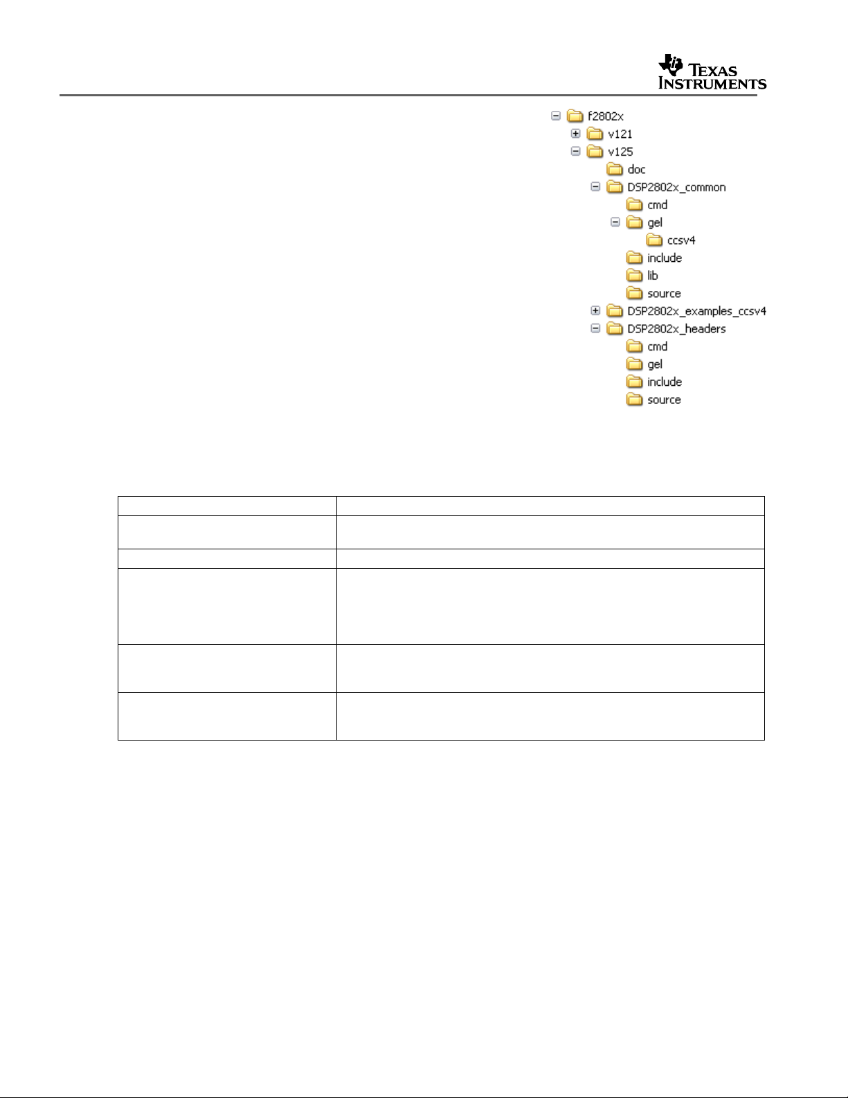
2.2 Where Files are Located (Directory Structure)
As installed, the 2802x C/C++ Header Files and Peripheral
Examples is partitioned into a well-defined directory
structure.
Table 1 describes the contents of the main directories used
by DSP2802x header files and peripheral examples:
Table 1. DSP2802x Main Directory Structure
Directory Description
<base> Base install directory. For the rest of this document <base> will be omitted
from the directory names.
<base>\doc Documentation including the revision history from the previous release.
<base>\DSP2802x_headers Files required to incorporate the peripheral header files into a project .
The header files use the bit-field structure approach described in Section
3.
Integrating the header files into a new or existing project is described in
Section 5.
<base>\DSP2802x_examples_ccsv4 Example Code Composer Studio v4.0+ projects. These example projects
illustrate how to configure many of the on-chip peripherals. An overview of
the examples is given in Section 4.
<base>DSP2802x_common Common source files shared across example projects to illustrate how to
perform tasks using header file approach. Use of these files is optional,
but may be useful in new projects. A list of these files is in Section 8.
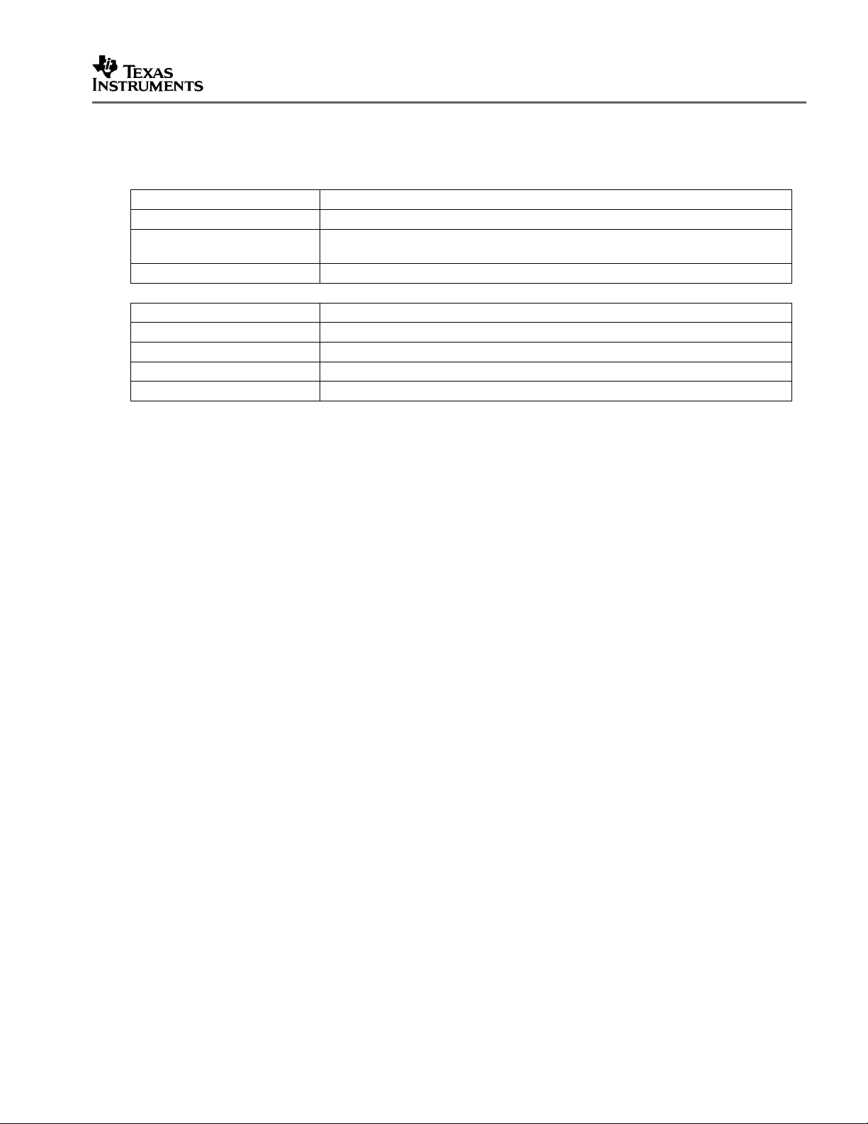
Under the DSP2802x_headers and DSP2802x_common directories the source files are
further broken down into sub-directories each indicating the type of file. Table 2 lists the sub-
4
Page 5
V1.25 Quick Start Readme
directories and describes the types of files found within each:
Table 2. DSP2802x Sub-Directory Structure
Sub-Directory Description
DSP2802x_headers\cmd Linker command files that allocate the bit-field structures described in Section 3.
DSP2802x_headers\source Source files required to incorporate the header files into a new or existing
project.
DSP2802x_headers\include Header files for each of the on-chip peripherals.
DSP2802x_common\cmd Example memory command files that allocate memory on the devices.
DSP2802x_common\include Common .h files that are used by the peripheral examples.
DSP2802x_common\source Common .c files that are used by the peripheral examples.
DSP2802x_common\lib Common library (.lib) files that are used by the peripheral examples.
DSP2802x_common\gel\ccsv4 Code Composer Studio v4.x GEL files for each device. These are optional.
5
Page 6

V1.25 Quick Start Readme
3 Understanding The Peripheral Bit-Field Structure Approach
The following application note includes useful information regarding the bit-field peripheral
structure approach used by the header files and examples.
This method is compared to traditional #define macros and topics of code efficiency and
special case registers are also addressed. The information in this application note is
important to understand the impact using bit fields can have on your application code.
Programming TMS320x28xx and 28xxx Peripherals in C/C++ (SPRAA85)
6
Page 7
V1.25 Quick Start Readme
4 Peripheral Example Projects
This section describes how to get started with and configure the peripheral examples
included in the 2802x Header Files and Peripheral Examples software package.
4.1 Getting Started
4.1.1 Getting Started in Code Composer Studio v4.0+
To get started, follow these steps to load the 32-bit CPU-Timer example. Other examples are
set-up in a similar manner.
1. Have a hardware platform connected to a host with Code Composer Studio
installed.
NOTE: As supplied, the ‘2802x example projects are built for the ‘28027 device. If you
are using another 2802x device, the memory definition in the linker command file
(.cmd) will need to be changed and the project rebuilt.
2. Open the example project.
Each example has its own project directory which is “imported”/opened in Code
Composer Studio v4.
To open the ‘2802x CPU-Timer example project directory, follow the following steps:
a. In Code Composer Studio v 4.x: Project->Import Existing CCS/CCE Eclipse Project.
b. Next to “Select Root Directory”, browse to the CPU Timer example directory:
DSP2802x_examples_ccsv4\cpu_timer. Select the Finish button.
This will import/open the project in the CCStudio v4 C/C++ Perspective project
window.
3. Edit DSP28_Device.h
Edit the DSP2802x_Device.h file and make sure the appropriate device/package
combination is selected. By default the 28027 PT package is selected.
/********************************************************************
* DSP2802x_headers\include\DSP2802x_Device.h
********************************************************************/
#define TARGET 1
//--------------------------------------------------------------------------// User To Select Target Device:
define DSP28_280200PT 0
#define DSP28_280200DA 0
#define DSP28_28020PT 0
#define DSP28_28020DA 0
#define DSP28_28021PT 0
#define DSP28_28021DA 0
7
Page 8

V1.25 Quick Start Readme
#define DSP28_28022PT 0
#define DSP28_28022DA 0
#define DSP28_28023PT 0
#define DSP28_28023DA 0
#define DSP28_28026PT 0
#define DSP28_28026DA 0
#define DSP28_28027PT TARGET
#define DSP28_28027DA 0
4. Edit DSP2802x_Examples.h
Edit DSP2802x_Examples.h and specify the clock rate, the PLL control register value
(PLLCR and DIVSEL). These values will be used by the examples to initialize the
PLLCR register and DIVSEL bits.
The default values will result in a 60Mhz SYSCLKOUT frequency.
/********************************************************************
* DSP2802x_common\include\DSP2802x_Examples.h
********************************************************************/
/*---------------------------------------------------------------------------- Specify the PLL control register (PLLCR) and divide select (DIVSEL) value.
-----------------------------------------------------------------------------*/
//#define DSP28_DIVSEL 0 // Enable /4 for SYSCLKOUT(default at reset)
//#define DSP28_DIVSEL 1 // Disable /4 for SYSCKOUT
#define DSP28_DIVSEL 2 // Enable /2 for SYSCLKOUT
//#define DSP28_DIVSEL 3 // Enable /1 for SYSCLKOUT
#define DSP28_PLLCR 12
//#define DSP28_PLLCR 11
//#define DSP28_PLLCR 10
//#define DSP28_PLLCR 9
//#define DSP28_PLLCR 8
//#define DSP28_PLLCR 7
//#define DSP28_PLLCR 6
//#define DSP28_PLLCR 5
//#define DSP28_PLLCR 4
//#define DSP28_PLLCR 3
//#define DSP28_PLLCR 2
//#define DSP28_PLLCR 1
//#define DSP28_PLLCR 0 // (Default at reset) PLL is bypassed in this mode
//----------------------------------------------------------------------------
In DSP2802x_Examples.h, also specify the SYSCLKOUT rate. This value is used to
scale a delay loop used by the examples. The default value is for a 60 Mhz
SYSCLKOUT. If you have a 50 Mhz device or a 40 MHz device you will need to adjust
these settings accordingly.
8
Page 9

V1.25 Quick Start Readme
/********************************************************************
* DSP2802x_common\include\DSP2802x_Examples.h
********************************************************************/
……
#define CPU_RATE 16.667L // for a 60MHz CPU clock speed (SYSCLKOUT)
//#define CPU_RATE 20.000L // for a 50MHz CPU clock speed (SYSCLKOUT)
//#define CPU_RATE 25.000L // for a 40MHz CPU clock speed (SYSCLKOUT)
//#define CPU_RATE 33.333L // for a 30MHz CPU clock speed (SYSCLKOUT)
……
In DSP2802x_Examples.h the target device chosen in DSP2802x_Device.h also
specifies the maximum SYSCLKOUT frequency (60 MHz, 50 Mhz, or 40 MHz) by
setting it to 1 and the other to 0 via compiler directives. This value is used by those
examples with timing dependent code (i.e. baud rates or other timing parameters) to
determine whether 60MHz code, 50 Mhz code, or 40MHz code should be run.
The default value is for 60Mhz SYSCLKOUT for the ‘28027 device. If you have
selected a 50 Mhz device or a 40 MHz device in DSP2802x_Device.h, the frequency
settings are adjusted accordingly. If you intend to run examples which use these
definitions at a different frequency, then the timing parameters in those examples must
be directly modified accordingly regardless of the setting here.
/********************************************************************
* DSP2802x_common\include\DSP2802x_Examples.h
********************************************************************/
……
#if (DSP28_28026PT||DSP28_28026DA||DSP28_28027PT||DSP28_28027DA) // 28026||28027
devices only
#define CPU_FRQ_60MHZ 1 // 60 Mhz CPU Freq (10 MHz input clock)
#define CPU_FRQ_50MHZ 0
#define CPU_FRQ_40MHZ 0
#elif (DSP28_28023PT||DSP28_28023DA||DSP28_28022PT||DSP28_28022DA) // 28023||28023
devices
#define CPU_FRQ_60MHZ 0
#define CPU_FRQ_50MHZ 1 // 50 MHz CPU Freq (10 MHz input clock)
#define CPU_FRQ_40MHZ 0
#else // 28021||28020||280200 devices
#define CPU_FRQ_60MHZ 0
#define CPU_FRQ_50MHZ 0
#define CPU_FRQ_40MHZ 1 // 40 MHz CPU Freq (10 MHz input clock)
#endif//----------------------------------------------------------------------------
5. Review the comments at the top of the main source file:
Example_2802xCpuTimer.c.
A brief description of the example and any assumptions that are made and any external
hardware requirements are listed in the comments at the top of the main source file of
each example. In some cases you may be required to make external connections for the
example to work properly.
6. Perform any hardware setup required by the example.
9
Page 10
V1.25 Quick Start Readme
Perform any hardware setup indicated by the comments in the main source. The CPUTimer example only requires that the hardware be setup for “Boot to SARAM” mode.
Other examples may require additional hardware configuration such as connecting pins
together or pulling a pin high or low.
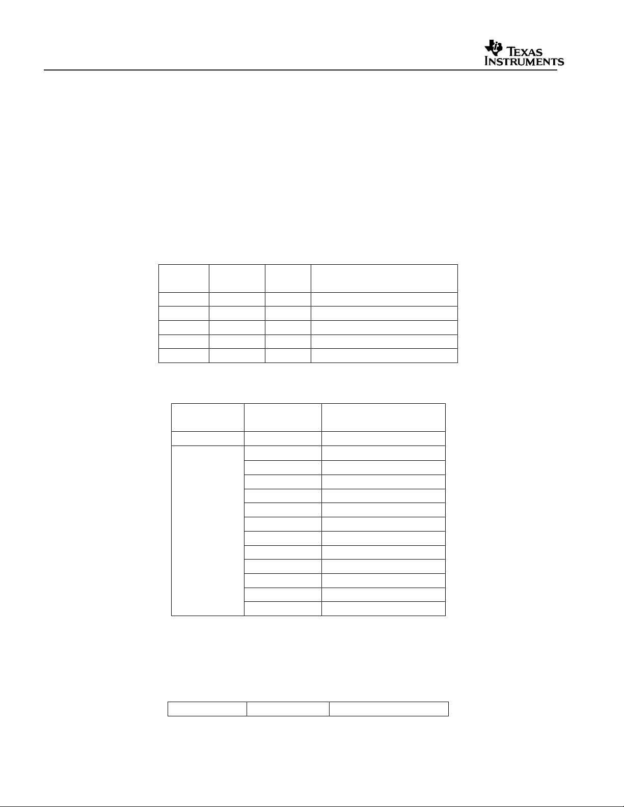
Table 3 shows a listing of the boot mode pin settings for your reference. Table 4 and
Table 5 list the EMU boot modes (when emulator is connected) and the Get Mode boot
mode options (mode is programmed into OTP) respectively. Refer to the documentation
for your hardware platform for information on configuring the boot mode pins. For more
information on the ‘2802x boot modes refer to the device specific Boot ROM Reference
Guide.
Table 3. 2802x Boot Mode Settings
GPIO37
TDO
X X 1 EMU Mode
0 0 0 Parallel I/O
0 1 0 SCI
1 0 0 Wait
1 1 0 “Get Mode”
GPIO34
CMP2OUT
TRSTn
Mode
Table 4. 2802x EMU Boot Modes (Emulator Connected)
EMU_KEY
0x0D00
!= 0x55AA x Wait
0x55AA
EMU_BMODE
0x0D01
0x0000 Parallel I/O
0x0001 SCI
0x0002 Wait
0x0003 Get Mode
0x0004 SPI
0x0005 I2C
0x0006 OTP
0x0007 Wait
0x0008 Wait
0x000A Boot to RAM
0x000B Boot to FLASH
Other Wait
Boot Mode Selected
10
Table 5. 2802x GET Boot Modes (Emulator Disconnected)
OTP_KEY OTP_BMODE Boot Mode Selected
Page 11
V1.25 Quick Start Readme
0x3D7BFE 0x3D7BFF
!= 0x55AA x Get Mode - Flash
0x55AA
When the emulator is connected for debugging:
TRSTn = 1, and therefore the device is in EMU boot mode. In this situation, the user must
write the key value of 0x55AA to EMU_KEY at address 0x0D00 and the desired EMU boot
mode value to EMU_BMODE at 0x0D01 via the debugger window according to Table 4. The
2802x gel files in the DSP2802x_common/gel/ directory have a GEL function – EMU Boot
Mode Select -> EMU_BOOT_SARAM() which performs the debugger write to boot to
“SARAM” mode when called.
When the emulator is not connected for debugging:
0x0001 Get Mode - SCI
0x0003 Get Mode – Flash
0x0004 Get Mode - SPI
0x0005 Get Mode - I2C
0x0006 Get Mode - OTP
Other Get Mode - Flash
SCI or Parallel I/O boot mode can be selected directly via the GPIO pins, or OTP_KEY at
address 0x3D7BFE and OTP_BMODE at address 0x3D7BFF can be programmed for the
desired boot mode per Table 5.
7. Build and Load the code
Once any hardware configuration has been completed, in Code Composer Studio v4, go
to Target->Debug Active Project.
This will open the “Debug Perspective” in CCSv4, build the project, load the .out file into
the 28x device, reset the part, and execute code to the start of the main function. By
default, in Code Composer Studio v4, every time Debug Active Project is selected, the
code is automatically built and the .out file loaded into the 28x device.
8. Run the example, add variables to the watch window or examine the memory
contents.
At the top of the code in the comments section, there should be a list of “Watch
variables”. To add these to the watch window, highlight them and right-click. Then
select Add Watch expression. Now variables of interest are added to the watch
window.
9. Experiment, modify, re-build the example.
If you wish to modify the examples it is suggested that you make a copy of the entire
header file packet to modify or at least create a backup of the original files first. New
examples provided by TI will assume that the base files are as supplied.
Sections 4.2 and 4.3 describe the structure and flow of the examples in more detail.
11
Page 12

V1.25 Quick Start Readme
10. When done, delete the project from the Code Composer Studio v4 workspace.
Go to View->C/C++ Projects to open up your project view. To remove/delete the project
from the workspace, right click on the project’s name and select delete. Make sure the Do
not delete contents button is selected, then select Yes. This does not delete the project
itself. It merely removes the project from the workspace until you wish to open/import it
again.
The examples use the header files in the DSP2802x_headers directory and shared
source in the DSP2802x_common directory. Only example files specific to a particular
example are located within in the example directory.
Note: Most of the example code included uses the .bit field structures to access
registers. This is done to help the user learn how to use the peripheral and device.
Using the bit fields has the advantage of yielding code that is easier to read and
modify. This method will result in a slight code overhead when compared to using
the .all method. In addition, the example projects have the compiler optimizer
turned off. The user can change the compiler settings to turn on the optimizer if
desired.
12
Page 13
4.2 Example Program Structure
V1.25 Quick Start Readme
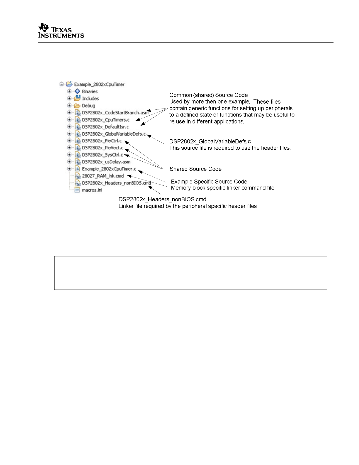
Each of the example programs has a very similar structure. This structure includes unique
source code, shared source code, header files and linker command files.
/********************************************************************
* DSP2802x_examples_ccsv4\cpu_timer\Example_2802xCpuTimer.c
********************************************************************/
#include "DSP28x_Project.h" // Device Headerfile and Examples Include File
• DSP28x_Project.h
This header file includes DSP2802x_Device.h and DSP2802x_Examples.h. Because the
name is device-generic, example/custom projects can be easily ported between different
device header files. This file is found in the <base>\DSP2802x_common\include
directory.
• DSP2802x_Device.h
This header file is required to use the header files. This file includes all of the required
peripheral specific header files and includes device specific macros and typedef
statements. This file is found in the <base>\DSP2802x_headers\include directory.
13
Page 14

V1.25 Quick Start Readme
• DSP2802x_Examples.h
This header file defines parameters that are used by the example code. This file is not
required to use just the DSP2802x peripheral header files but is required by some of the
common source files. This file is found in the <base>\DSP2802x_common\include
directory.
4.2.1 Source Code
Each of the example projects consists of source code that is unique to the example as well as
source code that is common or shared across examples.
• DSP2802x_GlobalVariableDefs.c
Any project that uses the DSP2802x peripheral header files must include this source file.
In this file are the declarations for the peripheral register structure variables and data
section assignments. This file is found in the <base>\DSP2802x_headers\source
directory.
• Example specific source code:
Files that are specific to a particular example have the prefix Example_2802x in their
filename. For example Example_2802xCpuTimer.c is specific to the CPU Timer
example and not used for any other example. Example specific files are located in the
<base>\DSP2802x_examples_ccsv4\<example> directory.
• Common source code:
The remaining source files are shared across the examples. These files contain
common functions for peripherals or useful utility functions that may be re-used. Shared
source files are located in the DSP2802x_common\source directory. Users may choose
to incorporate none, some, or the entire shared source into their own new or existing
projects.
4.2.2 Linker Command Files
Each example uses two linker command files. These files specify the memory where the
linker will place code and data sections. One linker file is used for assigning compiler
generated sections to the memory blocks on the device while the other is used to assign the
data sections of the peripheral register structures used by the DSP2802x peripheral header
files.
• Memory block linker allocation:
The linker files shown in 0 are used to assign sections to memory blocks on the device.
These linker files are located in the <base>\DSP2802x_common\cmd directory. Each
example will use one of the following files depending on the memory used by the example.
14
Page 15
V1.25 Quick Start Readme
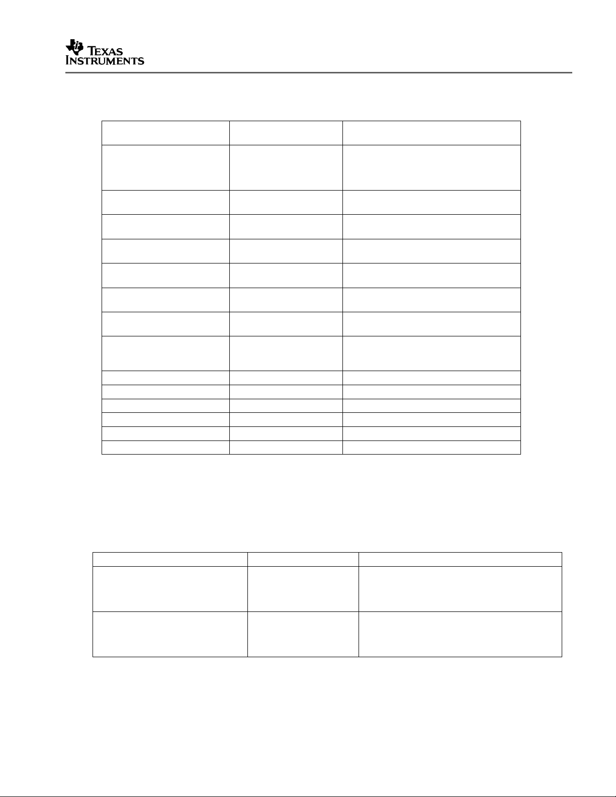
Table 6. Included Memory Linker Command Files
Memory Linker Command
File Examples
28027_RAM_lnk.cmd DSP2802x_common\cmd 28027 memory linker command file.
28026_RAM_lnk.cmd DSP2802x_common\cmd 28026 SARAM memory linker command
28023_RAM_lnk.cmd DSP2802x_common\cmd 28023 SARAM memory linker command
28022_RAM_lnk.cmd DSP2802x_common\cmd 28022 SARAM memory linker command
28021_RAM_lnk.cmd DSP2802x_common\cmd 28021 SARAM memory linker command
28020_RAM_lnk.cmd DSP2802x_common\cmd 28020 SARAM memory linker command
280200_RAM_lnk.cmd DSP2802x_common\cmd 280200 SARAM memory linker command
F28027.cmd DSP2802x_common\cmd F28027 memory linker command file.
F28026.cmd DSP2802x_common\cmd F28026 memory linker command file.
F28023.cmd DSP2802x_common\cmd F28023 memory linker command file.
F28022.cmd DSP2802x_common\cmd F28022 memory linker command file.
F28021.cmd DSP2802x_common\cmd F28021 memory linker command file.
F28020.cmd DSP2802x_common\cmd F28020 memory linker command file.
F280200.cmd DSP2802x_common\cmd F280200 memory linker command file.
Location Description
Includes all of the internal SARAM blocks
on 28027 device. “RAM” linker files do
not include flash or OTP blocks.
file.
file.
file.
file.
file.
file.
Includes all Flash, OTP and CSM
password protected memory locations.
• Header file structure data section allocation:
Any project that uses the header file peripheral structures must include a linker command
file that assigns the peripheral register structure data sections to the proper memory
location. These files are described in Table 7.
Table 7. DSP2802x Peripheral Header Linker Command File
Header File Linker Command File Location Description
DSP2802x_Headers_nonBIOS.cmd DSP2802x_headers\cmd Linker .cmd file to assign the header file
variables in a non-BIOS project. This file must
be included in any non-BIOS project that uses
the header files. Refer to section 5.2.
DSP2802x_Headers_nonBIOS.cmd DSP2833x_headers\cmd Linker .cmd file to assign the header file
variables in a non-BIOS project. This file must
be included in any non-BIOS project that uses
the header files. Refer to section 5.2.
15
Page 16

V1.25 Quick Start Readme
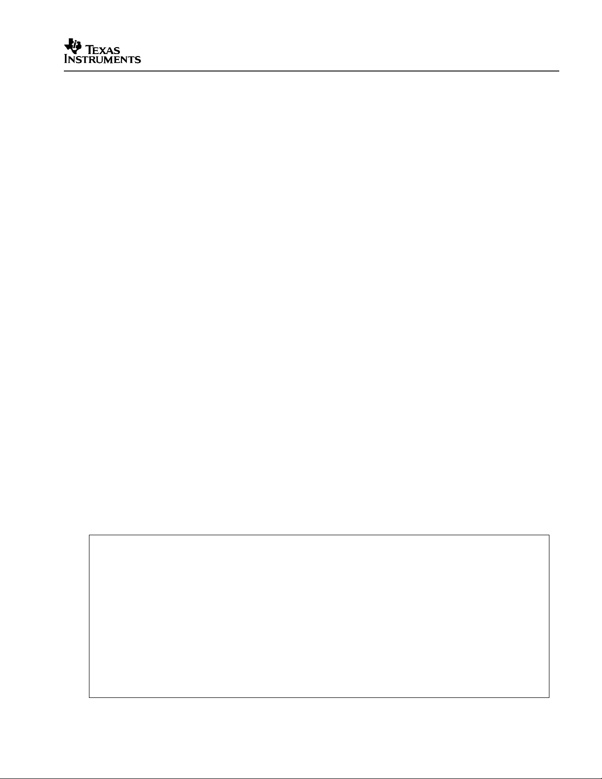
4.3 Example Program Flow
All of the example programs follow a similar recommended flow for setting up a 2802x device.
Figure 1 outlines this basic flow:
Reset
Boot Sequence
DSP2802x_CodeStartBranch.asm
Disable WD (Optional)
Branch to C Init Routine
C Init
main()
{
Initialize System Control
Boot ROM
During debug – user writes 0x55AA and boot
mode to EMU_KEY and EMU_BMODE then
Resets device again.
Standalone device – boot mode derived from
boot pins or OTP_KEY and OTP_BMODE
programmed locations.
DSP2802x_CodeStartBranch.asm
Used to re-direct code execution from the boot
entry point to the C Init routine.
Code can be configured to disable the
WatchDog if the WD is timing out before main()
is reached.
Assigned to the BEGIN section by the linker.
Located at 0x000000 for Boot to M0
Located at 0x3F7FF6 for Boot to Flash
C Init Routine
The Compiler's boot.asm which is
automatically included with the runtime
library. This will set OBJMODE to 28x.
Init PLL, Turn on Peripheral Clocks and set the
clock pre-scalers
Disable the WatchDog
Configure GPIO Pins to their peripheral function
or as an input or output as required by the
Initalize GPIO
Initialize PIE Vector Table
Initalize Peripherals
Example Specific Code
Enable Interrupts
}
Additional Functions and
Interrupt Service Routines
example.
Initalize the entire PIE Vector Table with pointers
to default Interrupt Service Routines (ISRs) found
in DSP2802x_DefaultIsr.c. It is useful for debug
purposes to have the entire table initalized even if
the ISR is not going to be used.
Remap PIE vectors used by the example to ISR
functions found within the example program.
Initalize the peripherals as required by the
example.
Enable the required PIE and CPU interrupts.
Any additional code required for the example.
Figure 1. Flow for Example Programs
16
Page 17

4.4 Included Examples:
Example Description
adc_soc ADC example to convert two channels: ADCINA4 and ADCINA2. Interrupts are
adc_temp_sensor ADC example – periodically performs conversions on internal channel ADCINA5
adc_temp_sensor_conv ADC example – periodically performs conversions on internal channel ADCINA5,
cpu_timer Configures CPU Timer0 and increments a count each time the ISR is serviced.
ecap_apwm This example sets up the alternate eCAP pins in the APWM mode
ecap_capture_pwm Captures the edges of a ePWM signal.
epwm_blanking_window Demonstrates blanking window by filtering out digital compare events
epwm_dceventtrip Sets up digital compare events, and uses combinations of these events to set
epwm_dcevent_trip_comp Sets up digital compare events with comparator inputs and uses combinations of
epwm_deadband Example deadband generation via ePWM3
epwm_timer_interrupts Starts ePWM1-ePWM6 timers. Every period an interrupt is taken for each ePWM.
epwm_trip_zone Uses the trip zone signals to set the ePWM signals to a particular state.
epwm_up_aq Generate a PWM waveform using an up count time base ePWM1-ePWM3 are
epwm_updown_aq Generate a PWM waveform using an up/down time base. ePWM- ePWM3 are
eqep_freqcal Frequency cal using eQEP1
eqep_pos_speed Pos/speed calculation using eQEP1
external_interrupt Configures GPIO0 as XINT1 and GPIO1 as XINT2. The interrupts are fired by
flash_f28027 ePWM timer interrupt project moved from SARAM to Flash for the F28027 device.
gpio_setup Three examples of different pinout configurations.
gpio_toggle Toggles all of the I/O pins using different methods – DATA, SET/CLEAR and
hrpwm Sets up ePWM1-ePWM4 and controls the edge of output A using the HRPWM
hrpwm_duty_sfo_v6 Use TI's MEP Scale Factor Optimizer (SFO) library to change the HRPWM duty
hrpwm_prdup_sfo_v6 Use TI’s MEP Scale Factor Optimizer (SFO) library to change the HRPWM period
hrpwm_prdupdown_sfo_v6 Use TI’s MEP Scale Factor Optimizer (SFO) library to change the HRPWM period
V1.25 Quick Start Readme
Table 8. Included Examples
enabled and PWM1 is configured to generate a periodic ADC SOC – ADCINT1.
which is connected to the ADC temperature sensor.
connected to the ADC temperature sensor, and converts the ADC result value to
Celsius or Kelvins. Only works on TMS 2802x devices.
around CTR = 0.
ePWM signals to a particular state.
these events to set ePWM signals to a particular state.
used.
used.
toggling GPIO30 and GPIO31 which are connected to XINT1 (GPIO0) and XINT2
(GPIO1) externally by the user.
Includes steps that were used to convert the project from SARAM to Flash. Some
interrupt service routines are copied from FLASH to SARAM for faster execution.
TOGGLE registers. The pins can be observed using an oscilloscope.
extension. Both rising edge and falling edge are controlled.
cycle.
in up-count mode.
in up-down count mode.
17
Page 18

V1.25 Quick Start Readme
Included Examples Continued…
hrpwm_slider This is the same as the hrpwm example except the control of CMPAHR is now
i2c_eeprom Communicate with an EEPROM via I2C
lpm_haltwake Puts device into low power halt mode. GPIO0 is configured to wake the device from
lpm_idlewake Puts device into low power idle mode. GPIO0 is configured as XINT1 pin. When an
lpm_standbywake Puts device into low power standby mode. GPIO0 is configured to wake the device
osc_comp Runs the oscillator compensation function on internal oscillator 1 or 2 to maintain
sci_echoback SCI-A example that can be used to echoback to a terminal program such as
scia_loopback SCI-A example that uses the peripheral’s loop-back test mode to send data.
scia_loopback_interrupts SCI-A example that uses the peripheral’s loop-back test mode to send data. Both
spi_loopback SPI-A example that uses the peripherals loop-back test mode to send data.
spi_loopback_interrupts SPI-A example that uses the peripherals loop-back test mode to send data. Both
sw_prioritized_interrupts The standard hardware prioritization of interrupts can be used for most applications.
timed_led_blink This example blinks GPIO34 (LED on the control card) at a rate of 1 Hz using CPU
watchdog Illustrates feeding the dog and re-directing the watchdog to an interrupt.
controlled by the user via a slider bar. The included .gel file sets up the slider.
halt when an external high-low-high pulse is applied to it.
XINT1 interrupt occurs due to a falling edge on GPIO0, the device is woken from
idle.
from halt when an external high-low-high pulse is applied to it.
oscillator frequency across temperature. Only works on TMS 2802x devices.
hyperterminal. A transceiver and a connection to a PC is required.
interrupts and FIFOs are used in this example.
interrupts and FIFOs are used in this example.
This example shows a method for software to re-prioritize interrupts if required.
Timer 0.
18
Page 19

V1.25 Quick Start Readme
4.5 Executing the Examples From Flash
Most of the DSP2802x examples execute from SARAM in “boot to SARAM” mode. One
example, DSP2802x_examples_ccsv4\flash_f28027, executes from flash memory in “boot to
flash” mode. This example is the PWM timer interrupt example with the following changes
made to execute out of flash:
1. Change the linker command file to link the code to flash.
Remove 28027_RAM_lnk.cmd from the project and link one of the flash based linker files
(ex: F28027.cmd, F28026.cmd, F28023.cmd, or F28022.cmd, F28021.cmd, F28020.cmd,
F280200.cmd). These files are located in the <base>DSP2802x_common\cmd\ directory.
2. Link DSP2802x_common\source\DSP2802x_CSMPasswords.asm to the project.
This file contains the passwords that will be programmed into the Code Security Module
(CSM) password locations. Leaving the passwords set to 0xFFFF during development is
recommended as the device can easily be unlocked. For more information on the CSM
refer to the appropriate System Control and Interrupts Reference Guide.
3. Modify the source code to copy all functions that must be executed out of SARAM
from their load address in flash to their run address in SARAM.
In particular, the flash wait state initialization routine must be executed out of SARAM.
In the DSP2802x, functions that are to be executed from SARAM have been assigned
to the ramfuncs section by compiler CODE_SECTION #pragma statements as shown
in the example below.
/********************************************************************
* DSP2802x_common\source\DSP2802x_SysCtrl.c
********************************************************************/
#pragma CODE_SECTION(InitFlash, "ramfuncs");
The ramfuncs section is then assigned to a load address in flash and a run address in
SARAM by the memory linker command file as shown below:
/********************************************************************
* DSP2802x_common\include\F28027.cmd
********************************************************************/
SECTIONS
{
ramfuncs : LOAD = FLASHA,
RUN = PRAML0,
LOAD_START(_RamfuncsLoadStart),
LOAD_END(_RamfuncsLoadEnd),
RUN_START(_RamfuncsRunStart),
PAGE = 0
}
19
Page 20

V1.25 Quick Start Readme
The linker will assign symbols as specified above to specific addresses as follows:
Address Symbol
Load start address RamfuncsLoadStart
Load end address RamfuncsLoadEnd
Run start address RamfuncsRunStart
These symbols can then be used to copy the functions from the Flash to SARAM using
the included example MemCopy routine or the C library standard memcopy() function.
To perform this copy from flash to SARAM using the included example MemCopy
function:
a. Link the file DSP2802x_common\source\DSP2802x_MemCopy.c to the project.
c. Add the following function prototype to the example source code. This is done for
you in the DSP2802x_Examples.h file.
/********************************************************************
* DSP2802x_common\include\DSP2802x_Examples.h
********************************************************************/
MemCopy(&RamfuncsLoadStart, &RamfuncsLoadEnd, &RamfuncsRunStart);
d. Add the following variable declaration to your source code to tell the compiler that
these variables exist. The linker command file will assign the address of each of
these variables as specified in the linker command file as shown in step 3. For the
DSP2802x example code this has is already done in DSP2802x_Examples.h.
/********************************************************************
* DSP2802x_common\include\DSP2802x_GlobalPrototypes.h
********************************************************************/
extern Uint16 RamfuncsLoadStart;
extern Uint16 RamfuncsLoadEnd;
extern Uint16 RamfuncsRunStart;
e. Modify the code to call the example MemCopy function for each section that needs to
be copied from flash to SARAM.
/********************************************************************
* DSP2802x_examples_ccsv4\flash_f28027 source file
********************************************************************/
MemCopy(&RamfuncsLoadStart, &RamfuncsLoadEnd, &RamfuncsRunStart);
20
Page 21

V1.25 Quick Start Readme
4. Modify the code to call the flash initialization routine:
This function will initialize the wait states for the flash and enable the Flash Pipeline mode.
/********************************************************************
* DSP2802x peripheral example .c file
********************************************************************/
InitFlash();
5. Set the required jumpers for “boot to Flash” mode.
The required jumper settings for each boot mode are shown in Table 9,
Table 10, and Table 11.
Table 9. 2802x Boot Mode Settings
GPIO37
TDO
X X 1 EMU Mode
0 0 0 Parallel I/O
0 1 0 SCI
1 0 0 Wait
1 1 0 “Get Mode”
GPIO34
CMP2OUT
TRSTn
Mode
Table 10. 2802x EMU Boot Modes (Emulator Connected)
EMU_KEY
0x0D00
!= 0x55AA x Wait
0x55AA
EMU_BMODE
0x0D01
0x0000 Parallel I/O
0x0001 SCI
0x0002 Wait
0x0003 Get Mode
0x0004 SPI
0x0005 I2C
0x0006 OTP
0x0007 Wait
0x0008 Wait
0x000A Boot to RAM
0x000B Boot to FLASH
Other Wait
Boot Mode Selected
21
Page 22

V1.25 Quick Start Readme
Table 11. 2802x GET Boot Modes (Emulator Disconnected)
OTP_KEY
0x3D7BFE
!= 0x55AA x Get Mode - Flash
0x55AA
OTP_BMODE
0x3D7BFF
0x0001 Get Mode - SCI
0x0003 Get Mode – Flash
0x0004 Get Mode - SPI
0x0005 Get Mode - I2C
0x0006 Get Mode - OTP
Other Get Mode - Flash
Boot Mode Selected
When the emulator is connected for debugging:
TRSTn = 1, and therefore the device is in EMU boot mode. In this situation, the user
must write the key value of 0x55AA to EMU_KEY at address 0x0D00 and the desired
EMU boot mode value to EMU_BMODE at 0x0D01 via the debugger window according
to Table 10.
When the emulator is not connected for debugging:
SCI or Parallel I/O boot mode can be selected directly via the GPIO pins, or OTP_KEY at
address 0x3D7BFE and OTP_BMODE at address 0x3D7BFF can be programmed for
the desired boot mode per the tables above
Refer to the documentation for your hardware platform for information on configuring the
boot mode selection pins.
For more information on the ‘2802x boot modes refer to the appropriate Boot ROM
Reference Guide.
6. Program the device with the built code.
In Code Composer Studio v4, when code is loaded into the device during debug, it
automatically programs to flash memory (if command linker file has any code allocated
to flash memory).
This can also be done using SDFlash available from Spectrum Digital’s website
(www.spectrumdigital.com)
These tools will be updated to support new devices as they become available. Please
check for updates.
22
Page 23

V1.25 Quick Start Readme
5 Steps for Incorporating the Header Files and Sample Code
Follow these steps to incorporate the peripheral header files and sample code into your own
projects. If you already have a project that uses the DSP280x or DSP281x header files then
also refer to Section 7 for migration tips.
5.1 Before you begin
Before you include the header files and any sample code into your own project, it is
recommended that you perform the following:
1. Load and step through an example project.
Load and step through an example project to get familiar with the header files and
sample code. This is described in Section 4.
2. Create a copy of the source files you want to use.
DSP2802x_headers: code required to incorporate the header files into your project
DSP2802x_common: shared source code much of which is used in the example
projects.
DSP2802x_examples_ccsv4: ‘2802x example projects that use the header files and
shared code.
5.2 Including the DSP2802x Peripheral Header Files
Including the DSP2802x header files in your project will allow you to use the bit-field structure
approach in your code to access the peripherals on the device. To incorporate the header
files in a new or existing project, perform the following steps:
1. #include “DSP2802x_Device.h” (or #include “DSP28x_Project.h” ) in your source
files.
The DSP2802x_Device.h include file will in-turn include all of the peripheral specific
header files and required definitions to use the bit-field structure approach to access the
peripherals.
/********************************************************************
* User’s source file
********************************************************************/
#include “DSP2802x_Device.h”
Another option is to #include “DSP28x_Project.h” in your source files, which in-turn
includes “DSP2802x_Device.h” and “DSP2802x_Examples.h” (if it is not necessary to
include common source files in the user project, the #include “DSP2802x_Examples.h”
line can be deleted). Due to the device-generic nature of the file name, user code is
easily ported between different device header files.
23
Page 24

V1.25 Quick Start Readme
/********************************************************************
* User’s source file
********************************************************************/
#include “DSP28x_Project.h”
2. Edit DSP2802x_Device.h and select the target you are building for:
In the below example, the file is configured to build for the ‘28027 device.
/********************************************************************
* DSP2802x_headers\include\DSP2802x_Device.h
********************************************************************/
#define TARGET 1
#define DSP28_28027 TARGET // Selects '28027
#define DSP28_28026 0 // Selects '28026
#define DSP28_28023 0 // Selects '28023… etc
By default, the ‘28027 device is selected.
3. Link the source file DSP2802x_GlobalVariableDefs.c to the project.
This file is found in the DSP2802x_headers\source\ directory and includes:
– Declarations for the variables that are used to access the peripheral registers.
– Data section #pragma assignments that are used by the linker to place the variables
in the proper locations in memory.
4. Link the appropriate DSP2802x header linker command file to the project.
As described in Section 3, when using the DSP2802x header file approach, the data
sections of the peripheral register structures are assigned to the memory locations of
the peripheral registers by the linker.
To perform this memory allocation in your project, one of the following linker command
files located in DSP2802x_headers\cmd\ must be included in your project:
– For non-DSP/BIOS† projects: DSP2802x_Headers_nonBIOS.cmd
– For DSP/BIOS projects: DSP2802x_Headers_BIOS.cmd
†
DSP/BIOS is a trademark of Texas Instruments
24
Page 25

V1.25 Quick Start Readme
The method for linking the header linker file to the project depends on personal
preference.
Method #1:
a. Right-click on the project in the project window of the C/C++ Projects perspective.
b. Select Link Files to Project…
c. Navigate to the DSP2802x_headers\cmd directory on your system and select the
desired .cmd file.
Note: The limitation with Method #1 is that the path to
<base>\DSP2802x_headers\cmd\<cmd file>.cmd is fixed on your PC. If you move
the installation directory to another location on your PC, the project will “break”
because it still expects the .cmd file to be in the original location. Use Method #2 if
you are using “linked variables” in your project to ensure your project/installation
directory is portable across computers and different locations on the same PC.
(For more information, see:
http://tiexpressdsp.com/index.php/Portable_Projects_in_CCSv4_for_C2000)
Method #2:
a. Right-click on the project in the project window of the C/C++ Projects perspective.
b. Select New->File.
c. Click on the Advanced>> button to expand the window.
d. Check the Link to file in the file system checkbox.
e. Select the Variables… button. From the list, pick the linked variable (macro defined in
your macros.ini file) associated with your installation directory. (For the 2802x header
files, this is INSTALLROOT_2802X_V<version #>). For more information on linked
variables and the macros.ini file, see:
http://tiexpressdsp.com/index.php/Portable_Projects_in_CCSv4_for_C2000#Method_
.232_for_Linking_Files_to_Project:
f. Click on the Extend…” button. Navigate to the desired .cmd file and select OK.
5. Add the directory path to the DSP2802x header files to your project.
To specify the directory where the header files are located:
a. Open the menu: Project->Properties.
b. In the menu on the left, select “C/C++ Build”.
c. In the “Tool Settings” tab, Select “C2000 Compiler -> Include Options:”
25
Page 26

V1.25 Quick Start Readme
d. In the “Add dir to #include search path (--include_path, -I” window, select the “Add”
icon in the top right corner.
e. Select the “File system…” button and navigate to the directory path of
DSP2802x_headers\include on your system.
6. Additional suggested build options:
The following are additional compiler and linker options. The options can all be set via
the Project-> Properties->Tool Settings sub-menus.
– C2000 Compiler:
-ml Select Runtime Modeul Options and check –ml
Build for large memory model. This setting allows data sections to reside
anywhere within the 4M-memory reach of the 28x devices.
-pdr Select Diagnostic Options and check –pdr
Issue non-serious warnings. The compiler uses a warning to indicate code that is
valid but questionable. In many cases, these warnings issued by enabling -pdr
can alert you to code that may cause problems later on.
– C2000 Linker:
-w Select Diagnostics and check –w
Warn about output sections. This option will alert you if any unassigned memory
sections exist in your code. By default the linker will attempt to place any
unassigned code or data section to an available memory location without alerting
the user. This can cause problems, however, when the section is placed in an
unexpected location.
-e Select Symbol Management and enter Program Entry Point –e
26
Defines a global symbol that specifies the primary entry point for the output
module. For the DSP2802x examples, this is the symbol “code_start”. This
Page 27

V1.25 Quick Start Readme
symbol is defined in the
DSP2802x_common\source\DSP2802x_CodeStartBranch.asm file. When you
load the code in Code Composer Studio, the debugger will set the PC to the
address of this symbol. If you do not define a entry point using the –e option,
then the linker will use _c_int00 by default.
5.3 Including Common Example Code
Including the common source code in your project will allow you to leverage code that is
already written for the device. To incorporate the shared source code into a new or existing
project, perform the following steps:
1. #include “DSP2802x_Examples.h” (or “DSP28x_Project.h”) in your source files.
The “DSP2802x_Examples.h” include file will include common definitions and
declarations used by the example code.
/********************************************************************
* User’s source file
********************************************************************/
#include “DSP2802x_Examples.h”
Another option is to #include “DSP28x_Project.h” in your source files, which in-turn
includes “DSP2802x_Device.h” and “DSP2802x_Examples.h”. Due to the devicegeneric nature of the file name, user code is easily ported between different device
header files.
/********************************************************************
* User’s source file
********************************************************************/
#include “DSP28x_Project.h”
27
Page 28

V1.25 Quick Start Readme
2. Add the directory path to the example include files to your project.
To specify the directory where the header files are located:
a. Open the menu: Project->Properties.
b. In the menu on the left, select “C/C++ Build”.
c. In the “Tool Settings” tab, Select “C2000 Compiler -> Include Options:”
d. In the “Add dir to #include search path (--include_path, -I” window, select the “Add”
icon in the top right corner.
e. Select the “File system…” button and navigate to the directory path of
DSP2802x_headers\include on your system.
3. Link a linker command file to your project.
The following memory linker .cmd files are provided as examples in the
DSP2802x_common\cmd directory. For getting started the basic
28027_RAM_lnk.cmd file is suggested and used by most of the examples.
Table 12. Included Main Linker Command Files
Memory Linker Command
File Examples
28027_RAM_lnk.cmd DSP2802x_common\cmd 28027 memory linker command file.
28026_RAM_lnk.cmd DSP2802x_common\cmd 28026 SARAM memory linker command
28023_RAM_lnk.cmd DSP2802x_common\cmd 28023 SARAM memory linker command
28022_RAM_lnk.cmd DSP2802x_common\cmd 28022 SARAM memory linker command
Location Description
Includes all of the internal SARAM blocks
on a 28027 device. “RAM” linker files do
not include flash or OTP blocks.
file.
file.
28
Page 29

V1.25 Quick Start Readme
file.
28021_RAM_lnk.cmd DSP2802x_common\cmd 28021 SARAM memory linker command
file.
28020_RAM_lnk.cmd DSP2802x_common\cmd 28020 SARAM memory linker command
file.
280200_RAM_lnk.cmd DSP2802x_common\cmd 280200 SARAM memory linker command
file.
F28027.cmd DSP2802x_common\cmd F28027 memory linker command file.
Includes all Flash, OTP and CSM
password protected memory locations.
F28026.cmd DSP2802x_common\cmd F28026 memory linker command file.
F28023.cmd DSP2802x_common\cmd F28023 memory linker command file.
F28022.cmd DSP2802x_common\cmd F28022 memory linker command file.
F28021.cmd DSP2802x_common\cmd F28021 memory linker command file.
F28020.cmd DSP2802x_common\cmd F28020 memory linker command file.
F280200.cmd DSP2802x_common\cmd F280200 memory linker command file.
4. Set the CPU Frequency
In the DSP2802x_common\include\DSP2802x_Examples.h file specify the proper CPU
frequency. Some examples are included in the file.
/********************************************************************
* DSP2802x_common\include\DSP2802x_Examples.h
********************************************************************/
……
#define CPU_RATE 16.667L // for a 60MHz CPU clock speed (SYSCLKOUT)
//#define CPU_RATE 20.000L // for a 50MHz CPU clock speed (SYSCLKOUT)
//#define CPU_RATE 25.000L // for a 40MHz CPU clock speed (SYSCLKOUT)
……
5. Link desired common source files to the project.
The common source files are found in the DSP2802x_common\source\ directory.
6. Include .c files for the PIE.
Since all catalog ‘2802x applications make use of the PIE interrupt block, you will want to
include the PIE support .c files to help with initializing the PIE. The shell ISR functions
can be used directly or you can re-map your own function into the PIE vector table
provided. A list of these files can be found in section 8.2.1.
29
Page 30

V1.25 Quick Start Readme
6 Troubleshooting Tips & Frequently Asked Questions
• In the examples, what do “EALLOW;” and “EDIS;” do?
EALLOW; is a macro defined in DSP2802x_Device.h for the assembly instruction
EALLOW and likewise EDIS is a macro for the EDIS instruction. That is EALLOW; is the
same as embedding the assembly instruction asm(“ EALLOW”);
Several control registers on the 28x devices are protected from spurious CPU writes by
the EALLOW protection mechanism. The EALLOW bit in status register 1 indicates if the
protection is enabled or disabled. While protected, all CPU writes to the register are
ignored and only CPU reads, JTAG reads and JTAG writes are allowed. If this bit has
been set by execution of the EALLOW instruction, then the CPU is allowed to freely write
to the protected registers. After modifying the registers, they can once again be
protected by executing the EDIS assembly instruction to clear the EALLOW bit.
For a complete list of protected registers, refer to TMS320x2802x System Control and
Interrupts Reference Guide .
• Peripheral registers read back 0x0000 and/or cannot be written to.
There are a few things to check:
• Peripheral registers cannot be modified or unless the clock to the specific peripheral
is enabled. The function InitPeripheralClocks() in the DSP2802x_common\source
directory shows an example of enabling the peripheral clocks.
• Some peripherals are not present on all 2802x family derivatives. Refer to the
device datasheet for information on which peripherals are available.
• The EALLOW bit protects some registers from spurious writes by the CPU. If your
program seems unable to write to a register, then check to see if it is EALLOW
protected. If it is, then enable access using the EALLOW assembly instruction.
TMS320x2802x System Control and Interrupts Reference Guide for a complete list
of EALLOW protected registers.
• Memory block L0, L1 read back all 0x0000.
In this case most likely the code security module is locked and thus the protected
memory locations are reading back all 0x0000. Refer to the for information on the code
security module.
• Code cannot write to L0 or L1 memory blocks.
In this case most likely the code security module is locked and thus the protected
memory locations are reading back all 0x0000. Code that is executing from outside of
the protected cannot read or write to protected memory while the CSM is locked. Refer
to the TMS320x2802x Control and Interrupts Reference Guide for information on the
code security module
30
Page 31

V1.25 Quick Start Readme
• A peripheral register reads back ok, but cannot be written to.
The EALLOW bit protects some registers from spurious writes by the CPU. If your
program seems unable to write to a register, then check to see if it is EALLOW protected.
If it is, then enable access using the EALLOW assembly instruction. TMS320x2802x
System Control and Interrupts Reference Guide for a complete list of EALLOW protected
registers.
• I re-built one of the projects to run from Flash and now it doesn’t work. What could
be wrong?
Make sure all initialized sections have been moved to flash such as .econst and .switch.
If you are using SDFlash, make sure that all initialized sections, including .econst, are
allocated to page 0 in the linker command file (.cmd). SDFlash will only program
sections in the .out file that are allocated to page 0.
• Why do the examples populate the PIE vector table and then re-assign some of the
function pointers to other ISRs?
The examples share a common default ISR file. This file is used to populate the PIE
vector table with pointers to default interrupt service routines. Any ISR used within the
example is then remapped to a function within the same source file. This is done for the
following reasons:
– The entire PIE vector table is enabled, even if the ISR is not used within the example.
This can be very useful for debug purposes.
– The default ISR file is left un-modified for use with other examples or your own
project as you see fit.
– It illustrates how the PIE table can be updated at a later time.
• When I build the examples, the linker outputs the following: warning: entry point
other than _c_int00 specified. What does this mean?
This warning is given when a symbol other then _c_int00 is defined as the code entry
point of the project. For these examples, the symbol code_start is the first code that is
executed after exiting the boot ROM code and thus is defined as the entry point via the –
e linker option. This symbol is defined in the DSP2802x_CodeStartBranch.asm file. The
entry point symbol is used by the debugger and by the hex utility. When you load the
code, CCS will set the PC to the entry point symbol. By default, this is the _c_int00
symbol which marks the start of the C initialization routine. For the DSP2802x examples,
the code_start symbol is used instead. Refer to the source code for more information.
• When I build many of the examples, the compiler outputs the following: remark:
controlling expression is constant. What does this mean?
Some of the examples run forever until the user stops execution by using a while(1) {}
loop The remark refers to the while loop using a constant and thus the loop will never be
exited.
• When I build some of the examples, the compiler outputs the following: warning:
statement is unreachable. What does this mean?
31
Page 32

V1.25 Quick Start Readme
Some of the examples run forever until the user stops execution by using a while(1) {}
loop. If there is code after this while(1) loop then it will never be reached.
• I changed the build configuration of one of the projects from “Debug” to “Release”
and now the project will not build. What could be wrong?
When you switch to a new build configuration (Project->Active Build Configuration) the
compiler and linker options changed for the project. The user must enter other options
such as include search path and the library search path. Open the build options menu
(Project-> Options) and enter the following information:
– C2000 Compiler, Include Options: Include search path
– C2000 Linker, File Search Path: Library search path
– C2000 Linker, File Search Path: Include libraries (ie rts2800_ml.lib)
Refer to section 5 for more details.
• In the flash example I loaded the symbols and ran to main. I then set a breakpoint
but the breakpoint is never hit. What could be wrong?
In the Flash example, the InitFlash function and several of the ISR functions are copied
out of flash into SARAM. When you set a breakpoint in one of these functions, Code
Composer will insert an ESTOP0 instruction into the SARAM location. When the
ESTOP0 instruction is hit, program execution is halted. CCS will then remove the
ESTOP0 and replace it with the original opcode. In the case of the flash program, when
one of these functions is copied from Flash into SARAM, the ESTOP0 instruction is
overwritten code. This is why the breakpoint is never hit. To avoid this, set the
breakpoint after the SARAM functions have been copied to SARAM.
• The eCAN control registers require 32-bit write accesses.
The compiler will instead make a 16-bit write accesses if it can in order to improve
codesize and/or performance. This can result in unpredictable results.
One method to avoid this is to create a duplicate copy of the eCAN control registers in
RAM. Use this copy as a shadow register. First copy the contents of the eCAN register
you want to modify into the shadow register. Make the changes to the shadow register
and then write the data back as a 32-bit value. This method is shown in the
DSP2802x_examples_ccsv4\ ecan_back2back example project.
6.1 Effects of read-modify-write instructions.
When writing any code, whether it be C or assembly, keep in mind the effects of read-modifywrite instructions.
The ‘28x DSP will write to registers or memory locations 16 or 32-bits at a time. Any
instruction that seems to write to a single bit is actually reading the register, modifying the
single bit, and then writing back the results. This is referred to as a read-modify-write
instruction. For most registers this operation does not pose a problem. A notable exception
is:
32
Page 33

V1.25 Quick Start Readme
6.1.1 Registers with multiple flag bits in which writing a 1 clears that flag.
For example, consider the PIEACK register. Bits within this register are cleared when writing
a 1 to that bit. If more then one bit is set, performing a read-modify-write on the register may
clear more bits then intended.
The below solution is incorrect. It will write a 1 to any bit set and thus clear all of them:
/********************************************************************
* User’s source file
********************************************************************/
PieCtrl.PIEACK.bit.Ack1 = 1; // INCORRECT! May clear more bits.
The correct solution is to write a mask value to the register in which only the intended bit will
have a 1 written to it:
/********************************************************************
* User’s source file
********************************************************************/
#define PIEACK_GROUP1 0x0001
……
PieCtrl.PIEACK.all = PIEACK_GROUP1; // CORRECT!
6.1.2 Registers with Volatile Bits.
Some registers have volatile bits that can be set by external hardware.
Consider the PIEIFRx registers. An atomic read-modify-write instruction will read the 16-bit
register, modify the value and then write it back. During the modify portion of the operation a
bit in the PIEIFRx register could change due to an external hardware event and thus the
value may get corrupted during the write.
The rule for registers of this nature is to never modify them during runtime. Let the CPU take
the interrupt and clear the IFR flag.
33
Page 34

V1.25 Quick Start Readme
7 Migration Tips for moving from the TMS320x280x or TMS320x281x
header files to the TMS320x2802x header files
This section includes suggestions for moving a project from the 280x header files to the
2802x header files.
1. Create a copy of your project to work with or back-up your current project.
2. Open the project file(s) in a text editor
In Code Composer Studio v4.x:
Open the .project, .cdtbuild, and macros.ini files in your example folder. Replace all
instances of 280x with 2802x so that the appropriate source files and build options are
used. Check the path names to make sure they point to the appropriate header file and
source code directories. Also replace the header file version number for the paths and
macro names as well where appropriate. For instance, if a macro name was
INSTALLROOT_280X_V170 for your 280x project using 280x header files V1.70,
change this to INSTALLROOT_2802X_V110 to migrate to the 2802x header files
V1.10. If not using the default macro name for your header file version, be sure to
change your macros according to your chosen macro name in the .project, .cdtbuild,
and macros.ini files.
3. Load the project into Code Composer Studio
Use the Edit-> find in files dialog to find instances of DSP280x_Device.h and
DSP280x_Example.h for 280x header files. Replace these with DSP2802x_Device.h
and DSP2802x_Example.h respectively (or instead with one DSP2802x_Project.h file).
4. Make sure you are using the correct linker command files (.cmd) appropriate for
your device and for the DSP2802x header files.
You will have one file for the memory definitions and one file for the header file structure
definitions. Using a 280x memory file can cause issues since the H0 memory block has
been split, renamed, and/or moved on the 2802x.
5. Build the project.
The compiler will highlight areas that have changed. If migrating from the TMS320x280x
header files, code should be mostly compatible after all instances of DSP280x are
replaced with DSP2802x in all relevant files, and the above steps are taken. Additionally,
several bits have been removed and/or replaced. See Table 13.
Table 13. Summary of Register and Bit-Name Changes from DSP280x V1.60
DSP2802x V1.00
Bit Name
Peripheral Register Old New Comment
SysCtrlRegs
XCLK Reserved(bit 6) XCLKINSEL(bit 6) On 2802x devices, XCLKIN can be fed via
a GPIO pin. This bit selects either GPIO38
(default) or GPIO19 as XCLKIN input
source.
34
Page 35

V1.25 Quick Start Readme
PLLSTS CLKINDIV(bit 1) DIVSEL (bits 8,7) DIVSEL allows more values by which
CLKIN can be divided.
Additionally, unlike the DSP280x devices, the DSP2802x devices run off an internal oscillator
(INTOSC1) by default. To switch between the 2 available internal clock sources and the
traditional external oscillator clock source, a new register in the System Control register space –
CLKCTL – is available.
8 Packet Contents:
This section lists all of the files included in the release.
8.1 Header File Support – DSP2802x_headers
The DSP2802x header files are located in the <base>\DSP2802x_headers\ directory.
8.1.1 DSP2802x Header Files – Main Files
The following files must be added to any project that uses the DSP2802x header files. Refer
to section 5.2 for information on incorporating the header files into a new or existing project.
Table 14. DSP2802x Header Files – Main Files
File Location Description
DSP2802x_Device.h DSP2802x_headers\include Main include file. Include this one file in any
of your .c source files. This file in-turn
includes all of the peripheral specific .h files
listed below. In addition the file includes
typedef statements and commonly used
mask values. Refer to section 5.2.
DSP2802x_GlobalVariableDefs.c DSP2802x_headers\source Defines the variables that are used to access
the peripheral structures and data section
#pragma assignment statements. This file
must be included in any project that uses the
header files. Refer to section 5.2.
DSP2802x_Headers_nonBIOS.cmd DSP2802x_headers\cmd Linker .cmd file to assign the header file
variables in a non-BIOS project. This file
must be included in any non-BIOS project
that uses the header files. Refer to section
5.2.
DSP2802x_Headers_nonBIOS.cmd DSP2802x_headers\cmd Linker .cmd file to assign the header file
variables in a non-BIOS project. This file
must be included in any non-BIOS project
that uses the header files. Refer to section
5.2.
35
Page 36

V1.25 Quick Start Readme
8.1.2 DSP2802x Header Files – Peripheral Bit-Field and Register Structure Definition
Files
The following files define the bit-fields and register structures for each of the peripherals on
the 2802x devices. These files are automatically included in the project by including
DSP2802x_Device.h. Refer to section 4.2 for more information on incorporating the header
files into a new or existing project.
Table 15. DSP2802x Header File Bit-Field & Register Structure Definition Files
File Location Description
DSP2802x_Adc.h DSP2802x_headers\include ADC register structure and bit-field definitions.
DSP2802x_BootVars.h DSP2802x_headers\include External boot variable definitions.
DSP2802x_Comp.h DSP2802x_headers\include Comparator register structure and bit-field
definitions.
DSP2802x_CpuTimers.h DSP2802x_headers\include CPU-Timer register structure and bit-field
definitions.
DSP2802x_DevEmu.h DSP2802x_headers\include Emulation register definitions
DSP2802x_ECap.h DSP2802x_headers\include eCAP register structures and bit-field definitions.
DSP2802x_EPwm.h DSP2802x_headers\include ePWM register structures and bit-field definitions.
DSP2802x_Gpio.h DSP2802x_headers\include General Purpose I/O (GPIO) register structures
and bit-field definitions.
DSP2802x_I2c.h DSP2802x_headers\include I2C register structure and bit-field definitions.
DSP2802x_NmiIntrupt.h DSP2802x_headers\include NMI interrupt register structure and bit-field
definitions
DSP2802x_PieCtrl.h DSP2802x_headers\include PIE control register structure and bit-field
definitions.
DSP2802x_PieVect.h DSP2802x_headers\include Structure definition for the entire PIE vector table.
DSP2802x_Sci.h DSP2802x_headers\include SCI register structure and bit-field definitions.
DSP2802x_Spi.h DSP2802x_headers\include SPI register structure and bit-field definitions.
DSP2802x_SysCtrl.h DSP2802x_headers\include System register definitions. Includes Watchdog,
PLL, CSM, Flash/OTP, Clock registers.
DSP2802x_XIntrupt.h DSP2802x_headers\include External interrupt register structure and bit-field
definitions.
36
Page 37

8.1.3 Variable Names and Data Sections
This section is a summary of the variable names and data sections allocated by the
DSP2802x_headers\source\DSP2802x_GlobalVariableDefs.c file. Note that all peripherals
may not be available on a particular 2802x device. Refer to the device datasheet for the
peripheral mix available on each 2802x family derivative.
Table 16. DSP2802x Variable Names and Data Sections
Peripheral Starting Address Structure Variable Name
ADC 0x007100 AdcRegs
ADC Mirrored Result Registers 0x000B00 AdcMirror
Code Security Module 0x000AE0 CsmRegs
Code Security Module Password
Locations
COMP1 0x006400 Comp1Regs
COMP2 0x006420 Comp2Regs
CPU Timer 0 0x000C00 CpuTimer0Regs
CPU Timer 1 0x000C08 CpuTimer1Regs
CPU Timer 2 0x000C10 CpuTimer2Regs
Device and Emulation Registers 0x000880 DevEmuRegs
System Power Control Registers 0x000985 SysPwrCtrlRegs
ePWM1 0x006800 EPwm1Regs
ePWM2 0x006840 EPwm2Regs
ePWM3 0x006880 EPwm3Regs
ePWM4 0x0068C0 EPwm4Regs
eCAP1 0x006A00 ECap1Regs
External Interrupt Registers 0x007070 XIntruptRegs
Flash & OTP Configuration Registers 0x000A80 FlashRegs
General Purpose I/O Data Registers 0x006fC0 GpioDataRegs
General Purpose Control Registers 0x006F80 GpioCtrlRegs
General Purpose Interrupt Registers 0x006fE0 GpioIntRegs
I2C 0x007900 I2caRegs
NMI Interrupt 0x7060 NmiIntruptRegs
PIE Control 0x000CE0 PieCtrlRegs
SCI-A 0x007050 SciaRegs
SPI-A 0x007040 SpiaRegs
0x3F7FF80x3F7FFF
V1.25 Quick Start Readme
CsmPwl
37
Page 38

V1.25 Quick Start Readme
zedDefaultIsr.c
8.2 Common Example Code – DSP2802x_common
8.2.1 Peripheral Interrupt Expansion (PIE) Block Support
In addition to the register definitions defined in DSP2802x_PieCtrl.h, this packet provides the
basic ISR structure for the PIE block. These files are:
Table 17. Basic PIE Block Specific Support Files
File Location Description
DSP2802x_DefaultIsr.c DSP2802x_common\source Shell interrupt service routines (ISRs) for the entire PIE
vector table. You can choose to populate one of
functions or re-map your own ISR to the PIE vector
table. Note: This file is not used for DSP/BIOS
projects.
DSP2802x_DefaultIsr.h DSP2802x_common\include Function prototype statements for the ISRs in
DSP2802x_DefaultIsr.c. Note: This file is not used for
DSP/BIOS projects.
DSP2802x_PieVect.c DSP2802x_common\source Creates an instance of the PIE vector table structure
initialized with pointers to the ISR functions in
DSP2802x_DefaultIsr.c. This instance can be copied to
the PIE vector table in order to initialize it with the default
ISR locations.
In addition, the following files are included for software prioritization of interrupts. These files
are used in place of those above when additional software prioritization of the interrupts is
required. Refer to the example and documentation in
DSP2802x_examples_ccsv4\sw_prioritized_interrupts for more information.
Table 18. Software Prioritized Interrupt PIE Block Specific Support Files
File Location Description
DSP2802x_SWPrioriti
DSP2802x_SWPrioritizedIsrLevels.h DSP2802x_common\include Function prototype statements for the ISRs
DSP2802x_SWPrioritizedPieVect.c DSP2802x_common\source Creates an instance of the PIE vector table
DSP2802x_common\source Default shell interrupt service routines
(ISRs). These are shell ISRs for all of the
PIE interrupts. You can choose to
populate one of functions or re-map your
own interrupt service routine to the PIE
vector table. Note: This file is not used
for DSP/BIOS projects.
in DSP2802x_DefaultIsr.c. Note: This file
is not used for DSP/BIOS projects.
structure initialized with pointers to the
default ISR functions that are included in
DSP2802x_DefaultIsr.c. This instance can
be copied to the PIE vector table in order
to initialize it with the default ISR locations.
38
Page 39

8.2.2 Peripheral Specific Files
Several peripheral specific initialization routines and support functions are included in the
peripheral .c source files in the DSP2802x_common\src\ directory. These files include:
Table 19. Included Peripheral Specific Files
File Description
DSP2802x_GlobalPrototypes.h Function prototypes for the peripheral specific functions included in these files.
DSP2802x_Adc.c ADC specific functions and macros.
DSP2802x_Comp.c Comparator specific functions and macros
DSP2802x_CpuTimers.c CPU-Timer specific functions and macros.
DSP2802x_ECap.c eCAP module specific functions and macros.
DSP2802x_EPwm.c ePWM module specific functions and macros.
DSP2802x_EPwm_defines.h #define macros that are used for the ePW M examples
DSP2802x_Gpio.c General-purpose IO (GPIO) specific functions and macros.
DSP2802x_I2C.c I2C specific functions and macros.
DSP2802x_I2c_defines.h #define macros that are used for the I2C examples
DSP2802x_PieCtrl.c PIE control specific functions and macros.
DSP2802x_Sci.c SCI specific functions and macros.
DSP2802x_Spi.c SPI specific functions and macros.
DSP2802x_SysCtrl.c System control (watchdog, clock, PLL etc) specific functions and macros.
Note: The specific routines are under development and may not all be available as of this release. They will be
added and distributed as more examples are developed.
V1.25 Quick Start Readme
39
Page 40

V1.25 Quick Start Readme
8.2.3 Utility Function Source Files
Table 20. Included Utility Function Source Files
File Description
DSP2802x_CodeStartBranch.asm Branch to the start of code execution. This is used to re-direct code
execution when booting to Flash, OTP or M0 SARAM memory. An option to
disable the watchdog before the C init routine is included.
DSP2802x_DBGIER.asm Assembly function to manipulate the DEBIER register from C.
DSP2802x_DisInt.asm Disable interrupt and restore interrupt functions. These functions allow you
to disable INTM and DBGM and then later restore their state.
DSP2802x_usDelay.asm Assembly function to insert a delay time in microseconds. This function is
cycle dependant and must be executed from zero wait-stated RAM to be
accurate.
Refer to DSP2802x_examples_ccsv4/adc_soc for an example of its use.
DSP2802x_CSMPasswords.asm Include in a project to program the code security module passwords and
reserved locations.
8.2.4 Example Linker .cmd files
Example memory linker command files are located in the DSP2802x_common\cmd directory.
For getting started the basic 28027_RAM_lnk.cmd file is suggested and used by many of the
included examples.
The L0 SARAM block is mirrored on these devices. For simplicity these memory maps only
include one instance of these memory blocks.
Table 21. Included Main Linker Command Files
Memory Linker Command
File Examples
28027_RAM_lnk.cmd DSP2802x_common\cmd 28027 memory linker command file.
28026_RAM_lnk.cmd DSP2802x_common\cmd 28026 SARAM memory linker command
28023_RAM_lnk.cmd DSP2802x_common\cmd 28023 SARAM memory linker command
28022_RAM_lnk.cmd DSP2802x_common\cmd 28022 SARAM memory linker command
28021_RAM_lnk.cmd DSP2802x_common\cmd 28021 SARAM memory linker command
28020_RAM_lnk.cmd DSP2802x_common\cmd 28020 SARAM memory linker command
280200_RAM_lnk.cmd DSP2802x_common\cmd 280200 SARAM memory linker command
F28027.cmd DSP2802x_common\cmd F28027 memory linker command file.
F28026.cmd DSP2802x_common\cmd F28026 memory linker command file.
Location Description
Includes all of the internal SARAM blocks
on a 28027 device. “RAM” linker files do
not include flash or OTP blocks.
file.
file.
file.
file.
file.
file.
Includes all Flash, OTP and CSM
password protected memory locations.
40
Page 41

F28023.cmd DSP2802x_common\cmd F28023 memory linker command file.
F28022.cmd DSP2802x_common\cmd F28022 memory linker command file.
F28021.cmd DSP2802x_common\cmd F28021 memory linker command file.
F28020.cmd DSP2802x_common\cmd F28020 memory linker command file.
F280200.cmd DSP2802x_common\cmd F280200 memory linker command file.
8.2.5 Example Library .lib Files
Example library files are located in the DSP2802x_common\lib directory. For this release the
IQMath library is included for use in the example projects. Please refer to the C28x IQMath
Library - A Virtual Floating Point Engine (SPRC087) for more information on IQMath and the
most recent IQMath library. The SFO libraries are also included for use in the example
projects. Please refer to TMS320x2802x HRPWM Reference Guide (SPRUGE8) for more
information on SFO library usage and the HRPWM module.
Table 22. Included Library Files
Main Liner Command File
Examples
IQmath.lib Please refer to the C28x IQMath Library - A Virtual Floating
IQmathLib.h IQMath header file.
SFO_TI_Build_V6.lib Please refer to the TMS320x2802x HRPWM Reference Guide
SFO_V6.h SFO V6 header file
V1.25 Quick Start Readme
Description
Point Engine (SPRC087) for more information on IQMath. This
is a fixed-point compiled library.
(SPRUGE8) for more information on the SFO V6 library.
41
Page 42

V1.25 Quick Start Readme
9 Detailed Revision History:
Changes from V1.21 to V1.25
Changes to Header Files:
a) DSP2802x_Adc.h – Added ADCCTL2 register to structure (this register does not
apply to Rev. 0 silicon).
Changes to Common Files:
b) DSP2802x_Adc.c – Added functions for re-calibrating the ADC trim registers.
c) DSP2802x_GlobalPrototypes.h – Added function prototypes for ADC re-calibration
functions.
d) f280200.gel – Added 1K L0 SARAM at 0x8000 mirrored at 0x3f8000
e) F280200.cmd and 280200_RAM_lnk.cmd – Added 1K L0 SARAM at 0x8000.
f) f28027.gel, f28026.gel, f28023.gel, f28022.gel, f28021.gel, f28020.gel, f280200.gel-
Modified GEL_Toolbar5() function for ccsv4 version of gels to support CCSv4. Also
modified gel so that Device_Cal does not run when only symbols are loaded.
Changes from V1.20 to V1.21
Changes to Header Files:
g) DSP2802x_SysCtrl.h – Added SysPwrCtrlRegs structure with BORCFG register.
h) DSP2802x_DevEmu.h – Removed BORCFG register (does not belong in this space).
i) DSP2802x_Headers_BIOS.cmd/DSP2802x_Headers_nonBIOS.cmd – Added
SysPwrCtrlRegs to 0x985-0x987, and reduced DevEmuRegs to 0x880-0x984.
j) DSP2802x_GlobalVariableDefs.c- Added SysPwrCtrlRegs declaration.
k) DSP2802x_Adc.c- Added changes to be implemented in Rev. A silicon (documented
in ADC reference guide. Not implemented in Rev. 0 silicon). Added ONESHOT bit to
SOCPRICTL register.
Changes to Common Files:
l) DSP2802x_TempSensorConv.c – changed return type to “int” instead of “unsigned
int”.
m) f28027.gel, f28026.gel, f28023.gel, f28022.gel, f28021.gel, f28020.gel, f280200.gel
– Changed Bypass() function such that PLLCR changed to 0 before DIVSEL set to
divide by 1 to prevent overshooting SYSCLKOUT frequency.
n) DSP2802x_Examples.h – add 50 Mhz support for 28022 and 28023 devices
Changes to Example Files:
42
Page 43

V1.25 Quick Start Readme
o) Example_2802xHRPWM_Duty_SFO_V6.c- Equations corrected. “0.5” in Q-format
should be added after MEP_ScaleFactor multiplied by fractional duty cycle.
p) Example_2802xSCI_Echoback.c, Example_2802xCpuTimer.c,
Example_2802xI2C_eeprom.c – support 50 MHz timings.
Changes from V1.10 to V1.20
Changes to Common Files:
q) SFO_TI_Build_V6.lib (SFO_TI_Build_V6b.lib) – Original SFO_TI_Build_V6.lib did
not automatically write the MEP_ScaleFactor into the HRMSTEP register.
SFO_TI_Build_V6b.lib now updates the HRMSTEP register with the
MEP_ScaleFactor value automatically. Additionally, added an errata document to the
/doc directory explaining the difference.
r) DSP2802x_OscComp.c – Adds functions required for internal oscillator frequency
compensation over temperature. The file is added to the /DSP2802x_common/source/
directory. Also added document in /doc directory explaining various functions defined
in this file.
s) DSP2802x_TempSensorConv.c- Adds functions required for ADC temp sensor to
convert digital ADC samples to Kelvin and Celsius temperature value. The file is
added to the /DSP2802x_common/source/ directory.
t) DSP2802x_GlobalPrototypes.h – Added function prototypes from
DSP2802x_OscComp.c and DSP2802x_TempSensorConv.c files.
u) DSP2802x_SysCtrl.c- Added “EALLOW” for XtalOscSel and ExtOscSel functions so
the bit settings take effect when calling these functions.
v) DSP2802x_Comp.c – Fixed typo in comments referring to SDAA and SCLA operation
– changed this to CMP1OUT and CMP2OUT.
w) DSP2802x_Epwm.c – Fixed typo in comments such that GPIO3 refers to EPWM2B
and not EPWM3B.
x) F28026.cmd, F28022.cmd, F280200.cmd – Split sectors A and B (size 0x2000) into
sectors A, B, C, and D (size 0x1000).
y) F280200.cmd- Split sector A (size 0x2000) into sector A and B (size 0x1000).
Changes to Example Files:
z) All CCSv4 example .cdtbuild Files- Replaced any hardcoded references to
“C:/tidcs/c28/DSP2802x/<version>” for OBJ and ASM directories and replaced with
“${INSTALLROOT_2802X_<version>}” macro. This did not affect CCSv4 project build
in previous version, but improves portability.
aa) Example_28021_Flash.pjt, Example_28020_Flash.pjt, Example_280200_Flash.pjt
– Added PJT files for 28021, 28020, and 280200 devices in the flash example
directory.
43
Page 44

V1.25 Quick Start Readme
bb) Example_2802xHRPWM_Duty_SFO_V6.c – Made “temp” a “Uint32” (unsigned long)
variable for proper operation.
cc) Example_2802xHRPWM_Duty_SFO_V6.pjt,
Example_2802xHRPWM_PrdUp_SFO_V6.pjt,
Example_2802xHRPWM_PrdUpDown_SFO_V6.pjt – Replaced
SFO_TI_Build_V6.lib with SFO_TI_Build_V6b.lib under source files.
dd) Example_2802xAdc_TempSensorConv– Added new example to convert ADC temp
sensor samples to Celsius or Kelvin temperature values.
ee) Example_2802xOscComp- Added new example to demonstrate oscillator frequency
compensation with temperature variation.
ff) Added DSP2802x_examples_ccsv4 directories - Added directories for CCSv4.x
projects. The example projects in these directories are identical to those found in the
normal CCSv3.x DSP2802x_examples directory with the exception that the examples
now support the Code Composer Studio v4.x project folder format instead of the Code
Composer Studio v3.x PJT files. The example gel files have also been removed for
the CCSv4 example projects because the gel file functions used in the example gels
are no longer supported.
Changes from V1.00 to V1.10
Changes to Header Files:
a) DSP2802x_Device.h – Removed 28024 and 28025 devices. Added 28021, 28020,
280200 devices.
b) DSP2802x_Gpio.h – Removed XCLKINSEL register (bit exists in XCLK register in
DSP2802x_SysCtrl.h file). Removed GPBPUD register structure.
c) DSP2802x_EPwm.h – Removed PWMSYNCSEL bit from HRPCTL register.
d) DSP2802x_Headers_BIOS.cmd – Added file (previously missing) to support
DSP/BIOS for 2802x.
e) DSP2802x_SysCtrl.h – Removed JTAGDEBUG register.
f) DSP2802x_DevEmu.h- Added BORCFG register.
g) DSP2802x_DefaultIsr.h- Added #defines for TINT1 to INT13 and TINT2 to INT14 so
change from TINT1 and TINT2 to INT13 and INT14 does not break pre-existing
projects.
Changes to Common Files:
44
Page 45

V1.25 Quick Start Readme
h) SFO_TI_Build_V6.lib and SFO_V6.h – SFO library updated to generate error code
of “2” when MEP_ScaleFactor>255 (previously returned “2” for
MEP_ScaleFactor>254). Additionally, the library now only updates the HRMSTEP
register used for auto-conversion with the calibrated MEP_ScaleFactor if
MEP_ScaleFactor<=255. Otherwise it will use the last “good” value written to
HRMSTEP for auto-conversions (previously, if the MEP_ScaleFactor>255, autoconversion could not be used).
i) f28024.gel and f28025.gel, 28024_RAM_lnk.cmd, 28025_RAM_lnk.cmd,
DSP2802x_Examples.h – Removed the 28024 and 28025 devices.
j) f28020.gel, f28021.gel, and f280200.gel, DSP2802x_Examples.h – Added the
28021, 28020, and 280200 devices.
k) All device gel files – Added HRPWR and HRMSTEP registers (previously missing),
fixed COMP register addresses. Removed PF3 from memory map. Removed
MAPCNF register. Added 0xD00-0xE00 to Page 0 memory map (specifically to allow
CCStudio to access these memories when using DSP/BIOS)
l) F28027.cmd- Changed CSM_PWL_PROG to CSM_PWL_P0 SECTION name to
match other devices.
m) All device .cmd files- Moved BOOT_RSVD to PAGE1 data space
n) CCSv4 gel files – Added ccsv4 directory in /gel directory for CCSv4-specific device
gel files (GEL_WatchAdd() functions removed).
o) DSP2802x_Adc.c – Change US_DELAY to 1000L instead of 5000L.
p) DSP2802x_SysCtrl.c – Replaced ExtClkSel() with XtalOscSel() and ExtOscSel()
functions.
q) DSP2802x_PieVect.c - Fix comment typos for ADCINT’s.
r) DSP2802x_PieVect.c, DSP2802x_SWPrioritizedPieVect.c,DSP2802x_DefaultIsr.c,
DSP2802x_SWPrioritizedDefaultIsr.c – Changed TINT1 and TINT2 to INT13 and
INT14, respectively.
s) Example_2802xAdcTempSensor - Added ADC temperature sensor project.
t) DSP2802x_CpuTimers.c – Corrected note that DSP/BIOS reserved CpuTimer2 only
and user must comment out CpuTimer2 code when using DSP/BIOS. CpuTimer0 and
1 have no such restriction.
Changes to Example Files:
u) All PJT Files- Removed the line: Tool="DspBiosBuilder" from all example PJT files for
easy migration path to CCSv4 Microcontroller-only (code-size limited) version users.
v) Example_28022_Flash.pjt – Replaced F28023.cmd with F28022.cmd.
w) All Flash example PJT files – Removed extra DSP2802x_usDelay.asm file.
x) Example_2802xAdcSoc.c – Added 2802x boot rom table to the top of the file.
45
Page 46

V1.25 Quick Start Readme
y) Example_2802xHRPWM_Duty_SFO_V6.c and
Example_2802xHRPWM_PrdUpDown_SFO_V6.c – Removed references to 2804
and replaced with 2802.
z) Example_2802xLPMHaltWake.c – Updated description comments for wakeup.
aa) Example_2802xLEDBlink- Added new example.
bb) Added DSP2802x_examples_ccsv4 directories - Added directories for CCSv4.x
projects. The example projects in these directories are identical to those found in the
normal CCSv3.x DSP2802x_examples directory with the exception that the examples
now support the Code Composer Studio v4.x project folder format instead of the Code
Composer Studio v3.x PJT files. The example gel files have also been removed for
the CCSv4 example projects because the gel file functions used in the example gels
are no longer supported.
V1.00
This version is the first customer release of the DSP2802x header files and examples.
46
Page 47

IMPORTANT NOTICE
Texas Instruments Incorporated and its subsidiaries (TI) reserve the right to make corrections, modifications, enhancements, improvements,
and other changes to its products and services at any time and to discontinue any product or service without notice. Customers should
obtain the latest relevant information before placing orders and should verify that such information is current and complete. All products are
sold subject to TI’s terms and conditions of sale supplied at the time of order acknowledgment.
TI warrants performance of its hardware products to the specifications applicable at the time of sale in accordance with TI’s standard
warranty. Testing and other quality control techniques are used to the extent TI deems necessary to support this warranty. Except where
mandated by government requirements, testing of all parameters of each product is not necessarily performed.
TI assumes no liability for applications assistance or customer product design. Customers are responsible for their products and
applications using TI components. To minimize the risks associated with customer products and applications, customers should provide
adequate design and operating safeguards.
TI does not warrant or represent that any license, either express or implied, is granted under any TI patent right, copyright, mask work right,
or other TI intellectual property right relating to any combination, machine, or process in which TI products or services are used. Information
published by TI regarding third-party products or services does not constitute a license from TI to use such products or services or a
warranty or endorsement thereof. Use of such information may require a license from a third party under the patents or other intellectual
property of the third party, or a license from TI under the patents or other intellectual property of TI.
Reproduction of TI information in TI data books or data sheets is permissible only if reproduction is without alteration and is accompanied
by all associated warranties, conditions, limitations, and notices. Reproduction of this information with alteration is an unfair and deceptive
business practice. TI is not responsible or liable for such altered documentation. Information of third parties may be subject to additional
restrictions.
Resale of TI products or services with statements different from or beyond the parameters stated by TI for that product or service voids all
express and any implied warranties for the associated TI product or service and is an unfair and deceptive business practice. TI is not
responsible or liable for any such statements.
TI products are not authorized for use in safety-critical applications (such as life support) where a failure of the TI product would reasonably
be expected to cause severe personal injury or death, unless officers of the parties have executed an agreement specifically governing
such use. Buyers represent that they have all necessary expertise in the safety and regulatory ramifications of their applications, and
acknowledge and agree that they are solely responsible for all legal, regulatory and safety-related requirements concerning their products
and any use of TI products in such safety-critical applications, notwithstanding any applications-related information or support that may be
provided by TI. Further, Buyers must fully indemnify TI and its representatives against any damages arising out of the use of TI products in
such safety-critical applications.
TI products are neither designed nor intended for use in military/aerospace applications or environments unless the TI products are
specifically designated by TI as military-grade or "enhanced plastic." Only products designated by TI as military-grade meet military
specifications. Buyers acknowledge and agree that any such use of TI products which TI has not designated as military-grade is solely at
the Buyer's risk, and that they are solely responsible for compliance with all legal and regulatory requirements in connection with such use.
TI products are neither designed nor intended for use in automotive applications or environments unless the specific TI products are
designated by TI as compliant with ISO/TS 16949 requirements. Buyers acknowledge and agree that, if they use any non-designated
products in automotive applications, TI will not be responsible for any failure to meet such requirements.
Following are URLs where you can obtain information on other Texas Instruments products and application solutions:
Products Applications
Amplifiers amplifier.ti.com Audio www.ti.com/audio
Data Converters dataconverter.ti.com Automotive www.ti.com/automotive
DLP® Products www.dlp.com Communications and www.ti.com/communications
DSP dsp.ti.com Computers and www.ti.com/computers
Clocks and Timers www.ti.com/clocks Consumer Electronics www.ti.com/consumer-apps
Interface interface.ti.com Energy www.ti.com/energy
Logic logic.ti.com Industrial www.ti.com/industrial
Power Mgmt power.ti.com Medical www.ti.com/medical
Microcontrollers microcontroller.ti.com Security www.ti.com/security
RFID www.ti-rfid.com Space, Avionics & www.ti.com/space-avionics-defense
RF/IF and ZigBee® Solutions www.ti.com/lprf Video and Imaging www.ti.com/video
Mailing Address: Texas Instruments, Post Office Box 655303, Dallas, Texas 75265
Copyright © 2010, Texas Instruments Incorporated
Telecom
Peripherals
Defense
Wireless www.ti.com/wireless-apps
 Loading...