


Texas Furnaces 2ac12030-2, 2ac12036-2 Installation Guide

LG
Installation Instructions & Use and care
MANUAL
LG
website http://www.LG.ca
LG Central Air Conditioning
Remote Condensing Unit
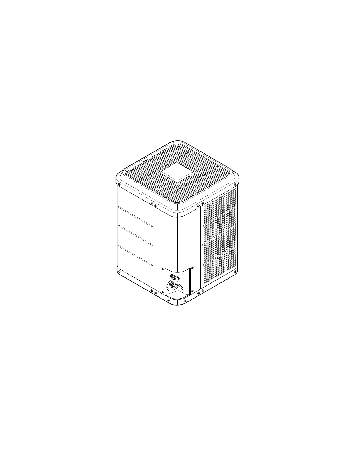
InstallationInstructions
These Instructions Should be carefully read and kept with the production for future reference
Attention Installer:
System installer’s guide
Check list (Page 11.) shall be
completed as per instructions

—2—
CONTENTS
INSTALLATION
SAFETY................................................................................................................................................................2
SHIPPING INSPECTION...............................................................................................................................
.......3
UNIT DIMENSIONS...............................................................................................................................
...............3
MINIMUM CLEARANCES...............................................................................................................................
.....3
INSTALLATION LOCATION...............................................................................................................................
.3
REMOVING EXISTING CONDENSING UNIT......................................................................................................3
REFRIGERANT HANDLING...............................................................................................................................
.4
LINE SET INSTALLATION...................................................................................................................................4
INSTALLATION....................................................................................................................................................5
METERING DEVICES...........................................................................................................................................5
BRAZING CONNECTIONS..................................................................................................................................5
LEAK JESTING....................................................................................................................................................5
EVACUATION.......................................................................................................................................................6
LINE SET REFRIGERANT(CHARGE) ADJUSTMENT AND RELEASE OF CHARGE ......................................7
ELECTRICAL........................................................................................................................................................7
CONDENSING UNIT WIRING DIAGRAM............................................................................................................8
SYSTEM START-UP / FINAL CHARGE ADJUSTMENT.....................................................................................8
FINAL CHARGE ADJUSTMENT..........................................................................................................................9
FOR TXV...............................................................................................................................................................9
FINAL CHECKS..................................................................................................................................................10
USE AND CARE
CARE AND MAINTENANCE..............................................................................................................................10
SYSTEM INSTALLER'S GUIDE - CHECK LIST................................................................................................11
USE AND CARE MANUAL ................................................................................................................................14
LIMITED WARRANTY........................................................................................................................................17
SAFETY
• Understand the following safety terms:
oDanger!- Identifies hazards that will result in personal injury or death.
o Warning! - Identifies hazards that could result in personal injury or death.
o Caution! - Identifies unsafe practices that will result in minor personal Injury, property damage, or
product damage.
• Read all installation instructions thoroughly prior to installing product.
• Warning! Always use disconnect switch to disconnect power to condensing unit prior to
opening control box. Never locate disconnect switch on unit.
• Caution! Follow all local plumbing, electrical, and any other codes that may apply.
• Wear safety glasses and gloves.
• EPA requires all refrigerant to be recovered. Do not blow charge into atmosphere.
• Danger! Do not sniff or inhale refrigerant. Personal injury and death is possible.
—3—
SHIPPING INSPECTION
This product was carefully inspected at the factory and released to the transportation company with no known
damage. Inspect carton for damage to help locate potential areas of damage. Remove carton and inspect entire
unit for damage. If damage is found, report it immediately to the carrier.
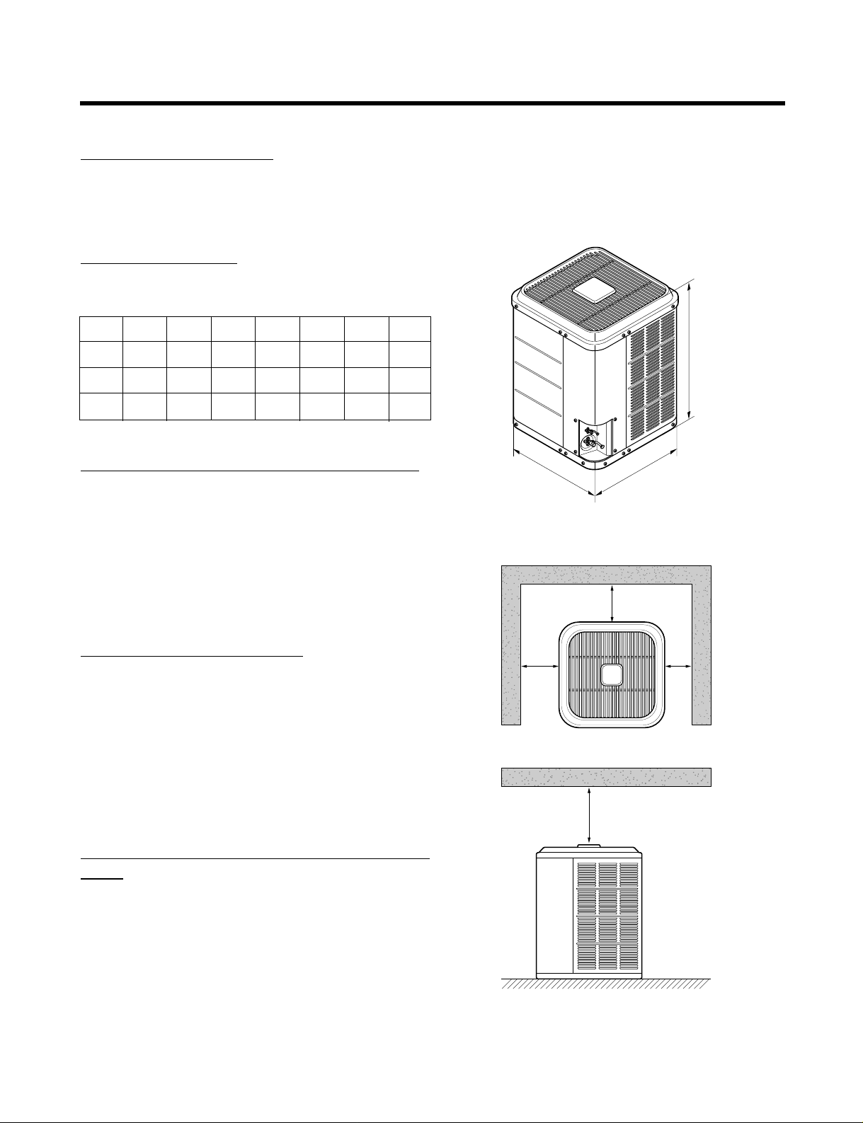
UNIT
DIM
ENSIONS
Physical Data, 12 SEER Models
12"
12" 6"
60"
SIDE VIEW
TOP VIEW
Fig. 1
C
BA
A
B
C
1.5 Ton
2421/32
2211/16
2711/16
2.0 Ton
2421/32
2211/16
2711/16
2.5 Ton
2421/32
2211/16
2711/16
3.0 Ton
2421/32
2211/16
2711/16
3.5 Ton
28
27
325/8
4.0 Ton
28
27
325/8
5.0 Ton
-
-
-
Table 1
MINIMUM CLEARANCES (SEE FIGURE 1)
• 30" clearance to service panel
• 6" clearance to one side of the unit.
• 12" clearance to two other sides of unit.
• 24" Clearance between two condensing units.
• 60" clearance above unit.
INSTALLATION LOCATION
•Away from windows
• Do not install under gas appliance vent
• At least 36" away from clothes dryer vent
• On a solid, level pad
• Isolated from the building structure (Avoid vibration
transmission)
REMOVING EXISTING CONDENSING
UNIT
• Warning! Electrical shock can cause severe
injury or death. Use disconnect switch to disconnect power to unit.
• Warning! Recover all refrigerant from prior
unit to avoid personal injury or death.
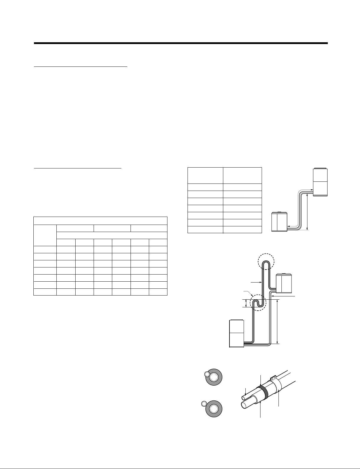
REFRIGERANT LINE LENGTH (ft)
COND 0 - 24 25 - 49 50 - 85
UNIT Line Diameter (in. OD)
(TONS) Suct Liq Suct Liq Suct Liq
1.5 3/4" 3/8" 3/4" 3/8" 3/4" 3/8"
2 3/4" 3/8" 3/4" 3/8" 3/4" 3/8"
2.5 3/4" 3/8" 7/8" 3/8" 7/8" 1/2"
3 3/4" 3/8" 7/8" 3/8" 1-
1/8"1/2
"
3.5 7/8"3/8"1-1/8"3/8"1-1/8"1/2
"
4 7/8"3/8"1-1/8"3/8"1-1/8"1/2
"
5 7/8"3/8"1-1/8"3/8"1-1/8"1/2
"
Table 2
—4—
REFRIGERANT HANDLING
• Warning! Do not sniff or inhale refrigerant. Personal injury or death may occur.
• Warning! Avoid contact with liquid refrigerant. Wear gloves and safety glasses to avoid frost-
bite and blindness.
• Warning! Never apply flame to refrigerant cylinder. Possible explosion resulting in personal
injury or death is possible.
• Warning! Never fill a cylinder more than 80% full of liquid refrigerant.
• Always recover refrigerant. EPA requires all refrigerant to be recovered.
• Warning! Always use EPA certified testing equipment and certified refrigerant tanks. Make
sure tanks have passed a hydrostatic test performed in last 5 years.
Outdoor unit
Max. 50ft
Max. "X"ft
Indoor unit
Outdoor unit
Must be above top of
condenser coil
Gas line
at each 35ft
Oil trap
6"
Indoor unit
Liquid line
Must be above top of
condenser coil
L
INE SET INSTALLATION
• Verify proper diameter sizes for liquid line and vapor
lines.
• Long line sets may require larger diameter vapor line
(See Table 2).
• The maximum line set length is listed in Table 3. Refer
to Figure 2 for dimension measurement.
• The factory oil charge is sufficient for Max. length in
table 3.
• Caution! Same line sets may require longer
than maximum. length listed in table 3, please
contact your wholesaler or/and distributor
before installation.
• Indoor unit may be a maximum of 50 feet above outdoor unit (See Figure 2).
• For every 35 feet that the outdoor unit is above the
indoor unit, an oil trap must be installed (See Figure 3).
• Vapor line must be insulated (See Figure 4).
• Insulate liquid line if ambient temperatures exceed
120˚F
• Liquid and vapor lines must not make metal-to-metal
contact.
• Avoid unnecessary turns.
Fig. 3
Fig. 2
Insulated vapor Line
Liquid Line
Tape
Sheet Metal Hanger
Incorrect
Correct
Fig. 4
COND UNIT LENGTH "X"
(TONS) IN FT MAX.
1.5 75
285
2.5 85
385
3.5 85
485
585
Table 3
—5—
INST
ALL
ATION
• Set unit on pad with electrical control box close to house.
• Bolt to pad if local codes require.
• If installed on rooftop, unit must be securely mounted with vibration isolators to prevent vibration transmission.
METERING DEVICES
For piston (0rifice):
• Indoor piston must be changed to required piston size provided with condensing unit. Piston size is listed on
rating plate.
• Piston is located between liquid line set and indoor coil distributor.
BRAZING CONNECTIONS
I. Ends of the refrigerant lines must be cut square, deburred, and cleaned.
2. Sweep refrigerant lines with Nitrogen or other inert gas.
3. Caution! Wrap service valve with wet rag to avoid overheating (It is recommended, to
removed the valve core prior to brazing).
4. Use a brazing alloy rod with minimum 2% silver.
5. After brazing, quench joint with water or wet rag and re-install vale core.
6. Re-install valve core, if removed.
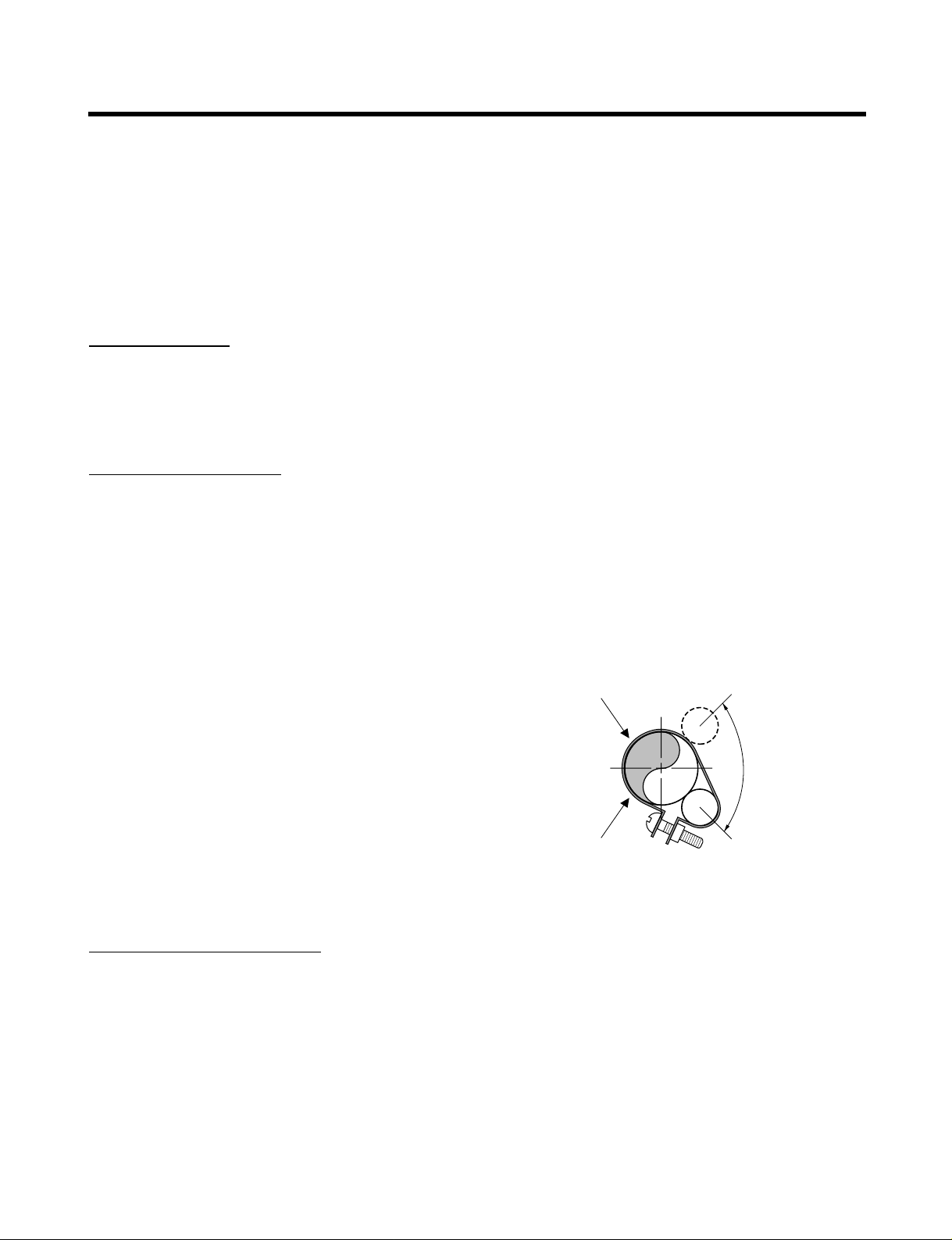
3/4" & smaller
vator line
on smaller lines,
bulb may be mounted
on top
do not mount
bulb on bottom
of line
7/8" & larger
vator line
Bulb
vator
Line
12
39
Fig. 5
For TXV:
• Caution! Remove piston located between liquid line set and indoor coil distributor.
• Screw TXV into distributor assembly.
• Connect pressure equalizer tube w/ flare nut to indoor
coil pressure port.
• Caution! Always make sure the suction line is
cleaned before clamping the bulb in place.
• On lines that are 3/4" O.D. or smaller, the bulb may
be installed on top of the line or side mounted (preferably at the 10 or 2 o'clock position) (See Figure 5).
• On lines that are 7/8" O.D. or larger, the remote bulb
should be installed at 45˚ or at approximately the 4 or
8 o'clock position (See Figure 5).
• Insulate temperature bulb with foam insulation.
• Do not make direct contact with ductwork, floor joists, wall studs, walls, and plumbing.
• Leave slack between building and unit to avoid vibration transmission.
• Seal wall penetration with RTV or other suitable caulk.
• Do not strap line set to joists with wire or strapping in direct contact.
• Liquid line filter drier is factory-installed in unit.