

Page 1

TD-104-5D
TD-104-5D-A
Wind Direction Sensor
User’s Manual
Texas Electronics, Inc.
5529 Redeld Street
Dallas, TX 75235
Tel.214.631.2490
Fax.214.631.4218
www.texaselectronics.com
Page 2
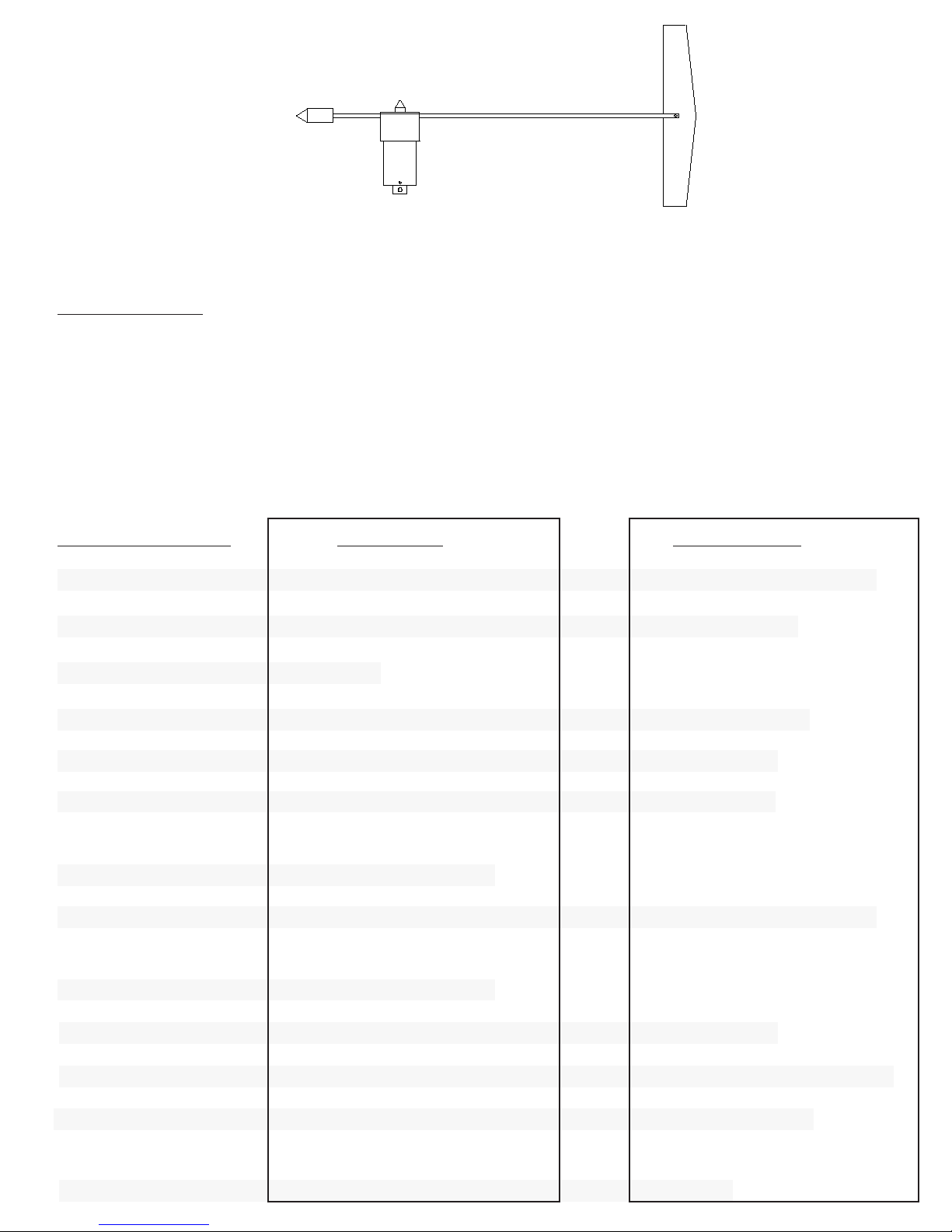
Model TD-104-5D Wind Direction Sensor
DESCRIPTION
e Texas Electronics, Inc. TD-104-5D Wind Direction Sensor is a mechanical style wind meter that measures
the horizontal wind azimuth. e sensor is intended for general long-term maintenance free operation.
e TD-104-5D Wind Direction Sensor is a freestanding device for measuring the direction of wind. e sensor
consists of a vane and counterweight assembly, which is mechanically coupled to a potentiometer (variable
resistor). As the vane rotates in the wind, the potentiometer changes resistance proportionally to the direction of
wind.
SPECIFICATIONS TD-104-5D TD-104-5D-A
Operating Range: 0-360° mechanical 0-360° mechanical
Signal Presentation: 10000 ohm potentiometer 4-20 mA
0-357° electrical 0-355° electrical
3 VDC excitation minimum 10-30 VDC
Performance:
Accuracy: +/- 3.0° +/- 3.0°
Potentiometer linearity: +/- 0.5% +/- 0.5%
Starting reshold: 2.5 mph (1.1 m/s) 2.5 mph (1.1 m/s)
Damping Ratio: 30.36 30.36
Damped Wavelength: 19.7' (6.0 m) 19.7’ (6.0 m)
Delay Distance: 4.8' (1.15 m) 4.8’ (1.15 m)
Resolution: 1° 1°
Environmental:
Operational Envelope: 0-135 mph (0 to 60 m/s) 0-135 mph (0 to 60 m/s)
Temperature: -40 to 160° F (-40 to 70° C) -40 to 160°F (-40 to 70°C)
Relative Humidity: 0-100% 0 to 100%
Physical:
Vane Overall Length: 33.8" (85.9 cm) 33.8” (85.9 cm)
Overall Height: 13.0" (33 cm) 13.0” (33 cm)
Turning Radius: 25.5" (65 cm) 25.5” (65 cm)
Weight: 1.75 lbs. (0.793 kg) less cable 1.75 lbs. (0.793 kg) less cable
Bearings: APEC 3 or better APEC 3 or better
Mounting Pole: 0.75" O.D. (1.9 cm) 0.75” O.D. (1.9 cm)
Cable: 60', 22 gauge 3 conductor 60’, 22 gauge 3 conductor
Warranty: 3 years 3 years
Page 3

FEATURES & BENEFITS
• Superior low starting threshold
• Long life hybrid single wiper potentiometer
• No plastic parts for extremely long life
• Precision stainless steel bearings for stability and repeatability
• Crossarm included with purchase of matching wind speed sensor
• Easy installation and maintenance
• Over 25 years in production
• Lightweight and rugged anodized aluminum exterior
INSTALLATION & MAINTENANCE
Installation consists of attaching the unit to a mast via the supplied mounting pole. If a crossarm is used,
the entire unit can be bolted to a mast or attached via U-bolts.
e sensor is dynamically calibrated at the factory and due to the nature of its operation should not require
eld calibration. Calibration is a matter of proper orientation during installation. A magnetic compass is
recommended for proper orientation. Field maintenance should include occasional cleaning of the vane
assembly and inspection of the internal mechanism to make sure it is free from insects and debris. In some
applications users may need to occasionally verify and document sensor accuracy with a calibration dial/
vane. Possible bearing and potentiometer replacement every three to ve years is recommended to maintain low starting threshold.
ORDERING INFORMATION
Model # Description
TD-104-5D Wind Direction Sensor, Heavy Industrial
TD-104-5D-A Wind Direction Sensor, 4-20 mA
* Sensor is designed to work with TV-114 wind speed sensor.
Optional Parts / Accessories
Page 4

PROPER EXPOSURE OF METEOROLOGICAL INSTRUMENTS
e following generally recognized guidelines depict ideal sensor mounting locations. ese guidelines are only
suggestions to aid the user in selecting optimum representative sampling locations for a particular sensor.
Reference was made to US Weather Bureau Installation criteria in preparing this data (See Reference 1).
WIND EQUIPMENT:
So far as available sites permit, wind sensors should be placed above the ground on a freely-exposed tower (20
feet or higher) and over terrain that is relatively level and free from obstructions to wind ow. When a compromise must be made, sensing units should be exposed at least 12 feet above any obstruction within 100 feet
and at least as high as any obstruction within 100 to 200 feet of the wind equipment. Support towers or masts
should not be of such bulk or shape as to create an appreciable obstruction to wind ow. Avoid sites where local
obstructions may create up-or-down dras, eddy currents or jet-ow eects. When sensors are roof-mounted,
they should be installed at least 10 feet (or more) from the roof surface, depending upon the particular installation site. Turbulence and other local eects can be reduced somewhat by mounting sensors on the upwind
end of the building (the end of the building exposed to the most common local prevailing winds). Horizontal-mount booms that extend from existing towers should be fabricated so that sensors will extend a distance of
5 to 10 feet from the tower assembly (dependent on tower thickness).
Wind direction sensors are oriented upon installation in reference to either true north or magnetic north. True
north is obtained by applying a local magnetic variation correction factor to a magnetic north compass indication (magnetic variation for a particular locality is obtainable from the nearest Weather Bureau Branch Oce).
Indicator readings for a true north sensor orientation will then be in terms of true geographic compass points.
All U.S. Weather Bureau surface wind data used for observational network reporting purposes and general public use is given in reference to this true north format. Indicator readings for a magnetic north sensor orientation
will be in terms of actual readings as would be obtained from directly viewing a magnetic compass instrument.
Wind direction data at Federal Aviation Agency and other aircra reporting facilities (for direct control tower-to-pilot utilization) is always made in reference to this magnetic north format.
Page 5
Page 6
Page 7
Page 8
Page 9

Warranty
Texas Electronics, Inc. (hereaer TEI) warrants the equipment manufactured by it to be free from defects in
material and workmanship. Upon return, transportation charges prepaid to TEI, within three (3) years of original shipment of sensors and one (1) year of original shipment of electronics, recorders and indicators, TEI will
repair or replace, at its option, any equipment which it determines to contain defective material or workmanship, and will return said equipment to purchaser, F.O.B., TEI. Texas Electronics shall not be obligated however to repair or replace equipment which has been repaired by others, abused, improperly installed, altered
or otherwise misused or damaged in any way. TEI will not be responsible for any dismantling, re-assembly, or
reinstallation charges.
is warranty is in lieu of all other warranties, expressed or implied. TEI shall not be liable for any special,
indirect, incidental or consequential damages claimed in connection with any rescission of this agreement by
purchaser.
 Loading...