

Page 1

Smart G-Force SB900, SB1200
DK Brugsanvisning
Texas A/S - Knullen 22 - DK-5260 Odense S - Denmark Version 17.1
Tel. +45 6395 5555 - www.texas.dk - post@texas.dk
Page 2

2
Indholdsfortegnelse ”Original brugsanvisning”
Indhold i pakken .................................................................................................................. 3
Beskrivelse af TEXAS’ robotplæneklipper ............................................................................. 4
Tekniske data ....................................................................................................................... 5
Sikkerhedssymboler ............................................................................................................. 6
Sikkerhedsforskrifter ............................................................................................................ 7
Vedligehold og vinteropbevari ng .......................................................................................... 9
Forberedelser til foråret. .................................................................................................... 10
Håndtering af robotplæneklipperen. .................................................................................. 10
Lynnedslagsbeskyttelse ...................................................................................................... 11
Grundlæggende funktionsprincipper for TEXAS’ Robotplæneklipper .................................. 12
Genkendelse af afgrænsningskabel .................................................................................... 14
Start og stop ved græsslåning ........................................................................................... 14
Klippebegrænsninger for TEXAS’ Rob ot plæneklipper ......................................................... 15
Indstilling af klippehøjde .................................................................................................... 16
Installationsguide ............................................................................................................... 17
Markering og placering af robotplæneklipperens arbejdsområdet ..................................... 25
Placering af ladestation. ..................................................................................................... 26
Udlægning af afgrænsningskabel. ...................................................................................... 28
Forbind afgrænsningskablet til ladestationen ..................................................................... 31
Opstart og test af installationen. ........................................................................................ 32
Programmering .................................................................................................................. 33
Forklaring af symboler på touch skærm ............................................................................. 36
Indstilling af tid og dato. .................................................................................................... 38
Klippecyklus indstilling ........................................................................................................ 40
Græsklipning ...................................................................................................................... 42
Opladning ........................................................................................................................... 43
Lås og oplåsning af skærm ................................................................................................ 43
Ændring af PIN-kode .......................................................................................................... 44
Regnsensor ........................................................................................................................ 46
Rengøring og udskiftning af reservedele ............................................................................ 46
Udskiftning af batteriet. ..................................................................................................... 48
Problemløsning for ladestation ........................................................................................... 49
Problemløsning for robotplæneklip per ............................................................................... 49
Fejlkoder. ........................................................................................................................... 51
CE overensstemmelseserklæring ........................................................................................ 52
Page 3

3
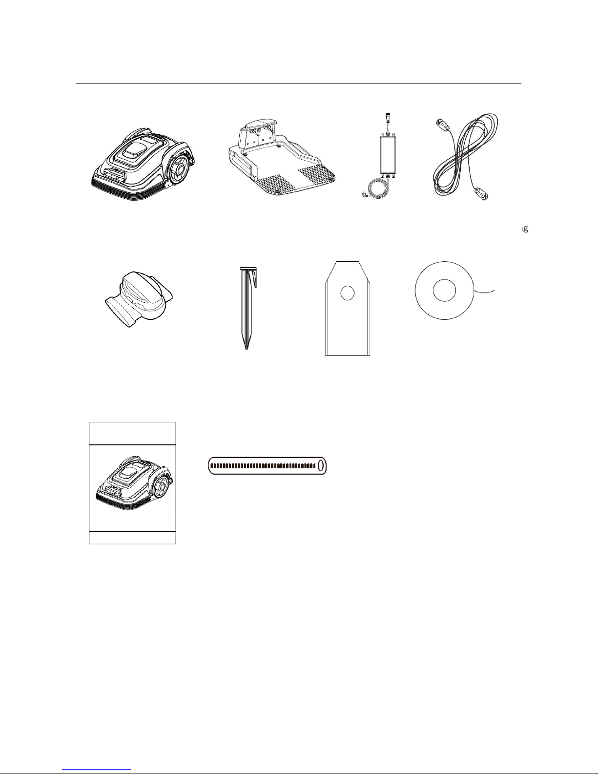
Indhold i pakken
(Varenummer:431757) (Varenummer:431756) (Varenummer:431758) (Varenummer: 431752)
Page 4

4
Beskrivelse af TEXAS’ robotplæneklipper
Tak fordi du har købt en TEXAS Robotplæneklipper.
På de næste par sider vil robotplæneklipperen og ladestationen blive forklaret og vist i
detaljer.
1. Robotplæneklipper
11. Hovedafbryder
2. Stop knap
12. Display
3. Display og touch skærm
13. Strømforsyning
4. Ladehorn
14. Forlængerkabel
5. Ladestation
15. Plastpløkker
6. Knive (3 Stk.)
16. Regn sensor
7. Knivholder
17. Afstandsmåler
8. Forhjul
18. Afgrænsningskabels amler
9. Baghjul
19. Afgrænsningskabel
10. Bærehåndtag
Page 5

5
Tekniske data
Art. nr.
90070200
90070201
Produkt
Smart G-force SB900
G-force SB1200
Motor specifikationer
Motor model
Batteri
Batteri
Motor type
24v, 2,0 amph
24v, 2,9 amph
Effekt
50W
50W
Drive system
Klippetid pr. opladning
45 min
60 min
Kapacitet
900 m^3
1200 m^3
Lade tid
70 min
70 min
Kørselshastighed
0,4m/s
0,4m/s
Instrument
Arbejdsbredde
18 cm
18 cm
Multiklip
Yes
Yes
Knivsystem
3 pcs. Flyvende
3 pcs. Flyvende
Arbejdshøjde min-max
20-60 mm
20-60 mm
Arbejdshøjdeinstillinger
5
5
Højdejustering
Central
Central
Klippedæk
Plastic
Plastic
Løftesensor
Yes
Yes
Forhindringssensor
Yes
Yes
Væltesensor
Yes
Yes
Tiltsensor
Yes
Yes
Regnsensor
Yes
Yes
Hældning
40%
40%
Multi-working område
1
1
Udstyr
Afgrænsningskabel
150 m
150 m
Pløkker
150 Stk.
150 Stk.
Ekstra Knive
6
6
Ladestation
1
1
Touch Skærm
Yes
Yes
Dimensioner
Klipper størrelse LxBxH
570X390 X 260 mm
570X390 X 260 mm
Vægt
8,5 kg
8,5 kg
Emissiondata
Lpa lydtryksniveau
46 dB
46 dB
Lwa usikkerhedsfaktor
0,35 dB
0,35 dB
LWA garanteret
67 dB
67 dB
Page 6
6
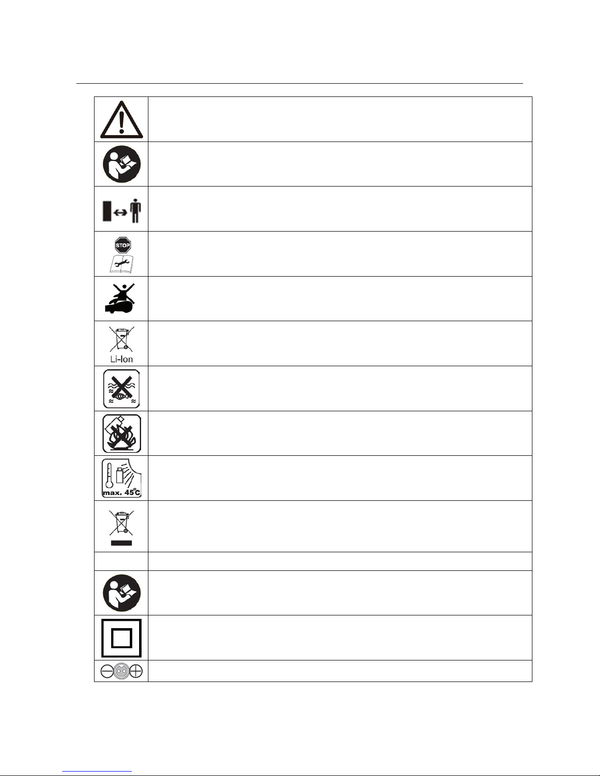
Sikkerhedssymboler
Advarsel! Maskinen kan ved skødesløs og forkert brug være et farligt
redskab, som kan forårsage alvorlige og i visse tilfælde livsfarlige skader.
Det er derfor vigtigt, at du læser og forstår indholdet af brugsanvisningen.
Læs brugsanvisningen før brug
Hold afstand til robotplæneklipperen når den er i aktion.
Hold hænder og fødder væk fra roterende knive. Put aldri g hænder el l er
fødder tæt på eller under maskinen, når robotplæneklipperen er i aktion.
Sørg for at afbryderknappen er sat på OFF, før der begyndes på
vedligeholdelse eller inspektion af maskinen.
Sid aldrig på maskinen.
Batteriet i robotplæneklipperen er af typen Li-ion.
Batteriet må ikke afskaffes via almindelig husholdningsaffald.
Batteriet skal afskaffes via genbrugsstationer.
Robotplæneklipper en må ikke dy ppes el l er kas tes under vand.
Udsæt aldrig robotplæneklipperen for ild
Udsæt ikke batteriet for stærk sollys over en længere periode eller over
max. 45 grader celsius.
Robotplæneklipper eller ladestation må ikke afskaffes via almindelig
husholdningsaffald, da produkterne indeholder elektronikske komponenter.
Produktet skal afleveres på genbrugsstationer eller andre faciliteter, der kan
håndtere genbrug af elektronik.
ADVARSELSSYSMBOLER PÅ LADESTATION.
Læs brugsanvisningen før brug
Dobbelt isoleret.
Kabel orientering
Page 7

7
Sikkerhedsforskrifter
ADVARSEL
Læs alle sikkerhedsadvarsler og alle instruktioner.
Ved arbejdet med robotplæneklipperen bør sikkerhedsanvisninger ne føl g es nøj e.
Gennemlæs brugsanvisningen grundigt inden du starter din maskine. Vær sikker på at du
omgående kan stoppe mask i n en i tilfælde af uheld.
Følges advarsler og sikkerhedsinstruktioner ikke, kan det være medvirkende til elektrisk
stød, ild og alvorlige personlige skader.
De advarsler, forholdsregler og instruktioner, der er beskrevet i denne brugsanvisning, kan
ikke dække alle de forhold eller situationer, der kan opstå. Brugeren må derfor anvende
sin sunde fornuft og udvise forsigtighed ved anvendelse af maskinen.
Sikkerhed
• Læs instruktionerne grundigt og vær sikker på, at du som forbruger forstår alle
instruktioner.
• Tillad ikke personer som ikke er bekendt med brugen af robotplæneklipperen, ej hellere
børn, betjene den.
• Lokale restriktioner kan indvirke på alderen af operatør en.
• Den, der betjener maskinen, er ansvarlig for andre personer i arbejdsområdet og deres
ejendele.
Brug af maskinen
• Sørg for afgrænsningskablet er monteret som anvist i manual.
• Efterse jævnligt det område hvor maskinen skal bruges og fjern alle sten, pinde og
andet affald, som vil kunne skade robotplæneklipperen.
• Efterse jævnligt knivene og knivbolte og om skæret er slidt eller beskadiget. Udskift
slidte eller beskadigede knive eller bolte om nødvendigt for at bevare balancen
• Maskinen må ikke bruges til andet arbejde end det, der er beskrevet i
brugsanvisningen.
• Brug kun originalt tilbehør og originale reservedele. Montering af ikke godkendte dele
kan medføre forøget risiko og er derfor ikke lovlig. Ethvert ansvar fraskrives ved ulykke
eller anden skade, som forårsages pga. montering af uoriginale dele.
• Brug ikke magt ved anvendelse af værktøjet. Brug det rette værktøj til opgaven.
Page 8

8
Generalt
• Brug ikke robotplæneklipperen uden plastskærmene sidder korrekt fast på maskinen.
• Hold ikke hænder og fødder i nærheden af roterende dele.
• Hold eller løft ikke robotplæneklipperen hvis en hjul- eller klippemotor kører.
• Tryk førs t på STOP knappen.
Sæt robotplæneklipperens hovedafbryder knap på OFF før:
- Fjernelse af alle typer snavs, eller blokerende genstande.
- Vedligehold, rengøring eller eftersyn robotplæneklipperen.
• Start robotplæneklipperen ifølge instrukserne. Når hovedafbryderknappen er sat på
ON, husk da at holde hænder og fødder væk fra roterende knive.
• Løft eller bær aldrig rundt på robotplæneklipperen med hovedafbryderknappen tændt.
• Lad ikke personer, der i kk e ved, hvordan robotplænekli p per en fungerer, bruge den.
• Put ikke noget ovenpå robotplæneklipperen ell er på ladestationen.
• Brug ikke robotplæneklipperen med beskadiget knive, plastskærme, bolte, skruer osv.
• Undgå at lad robotplæneklipperen køre i vådt græs.(Det vil kræve mere rengøring).
• Når plæneklipperen er sat til automatisk klippecyklus, skal der være opsyn med
robotplæneklipperen, hvis der er dyr, børn eller vokne på robottens klippeopmråde.
Page 9

9
Personlig sikkerhed
• Hvis hovedafbryderknappen er ødelagt eller ikke fungerer ordentligt, må
robotplæneklipperen ikke bruges. Læs mere w w w.texas.dk
• Vær altid opmærksom på, hvad du foretager dig og benyt sund fornuft, når du
anvender robotplæneklipperen.
• Mindreårige må ikke betjene maskinen.
• Maskinen må kun betjenes af personer, som er udhvilede og raske. Personer, der er
påvirket af alkohol, medicin eller euforiserede stoffer må ikke betjene robotten.
Vedligehold og vinteropbevaring
• Ved vinteropbevaring af robotplæneklipperen anbefales det, at robotten tages ind og
stå tørt og lunt og at slukke for hovedafbryderen (OFF) for at beskytte batteriet.
Oplad batteriet i robotplæneklipperen via den medfølgende ladestation, inden robotten
tages ind for vinteren.
Har man ikke mulighed for at have hele
robotten indenfor, kan batteriet også
tages ud og opbevares indenfor (Skal
være helt opladet)( Se bi l l ede)
Robotplæneklipperens batteri er et
vedligeholdesesfrit Lithium batteri, med
en estimeret levetid optil 5 år, afhængig
af brugen, omgivelserne samt
vintervedligehold.
Det anbefales at ladestationen også
tages indenfor om vinteren.
(Afgrænsningskablet skal IKKE tages op)
• Det er vigtigt at man oplader ro botplæneklipperen 2-3 gange i løbet af
vinteropbevaring en for at sik r e batter i e ts sundshedstilstand. Tag robotplæneklipper e n
ud og sæt den i ladestationen og lad den lade helt op. Derefter tages robotten igen ind
og stå tørt og lunt.
Bliver disse vinteropladninger ikke fulgt, vil der være risiko for at batteriet mister
kapacitet eller falder h el t sammen.
• Tjek alle bolte, skruer og møtrikker er spændt korret, da det sikrer de bedste
arbejdsbetingelser for robot ten.
• Udskift slidte og ødelagte reservedele. Brug kun orginale reservedele.
• Rens robotplæneklipperen grundigt for jord, græs, støv osv. Vær især opmærksom på
at få renset hjul og knivholder for at undgå ubalance i motorene.
Page 10

10
Forberedelser til foråret.
Efter vinteropbevaring er det en god ide at rengøre ladestikkene på ladestation og
ladeplader på robotplæneklipperen med en stål børste eller sandpapir. Det vil forbedre
strømforbindelse n ved opl ad ni ng .
Håndtering af robotplæneklipperen.
1. Det anbefales at transportere robotplæneklippere i orginalkassen, hvis det er over
større afstande.
2. Når robotten skal flyttes væk fra klippeområdet eller indstilles, skal den store røde
STOP knap aktiveret. (Se billede)
3. Når STOP knappen er aktiveres, skal hovedafbryderknappen dernæst trykkes til OFF
position, før robotten løftes helt op.
4. Luk topcover og løft robotten i det dertil indrettede bærehåndtag. Hold robotten så
knivene holdes væk fra kroppen for at undgå skader.
Page 11

11
Lynnedslagsbeskyttelse
For at beskytte robotplæneklipperen mo d ly nneds l ag anbefaldes det, at man ikke placere
ladestationen under eller i nærheden af et højt træ. Ligeledes må der heller ikke trækkes
forlængerledning til ladestation run dt omkr i ng hø j e træer .
Det anbefales at robotplæneklipperen ikke kører, når det er tordenvejr af hensyn til skader
på elektroniske komponenter ved lynnedslag. Ligeledes anb efales det helt at tage
strømmen fra ladestationen og, hvis det er muligt, at frakoble afgrænsni ng sk abl et i
ladestationen.
Page 12

12
Grundlæggende funktionsprincipper for TEXAS’ Robotplæneklipper
Robotplæneklipperen vælger kørselsretning vilkårligt. Det vil sige, at den ikke kører efter
noget bestemt mønster men blot tilfældigt rundt i haven. Det har den fordel, at den set
over en periode på en uges plænek li p ni ng vil nå rundt på hele plæneområdet inden f or
afgrænsningskablet.
Brugeren vælger selv hvor og hvordan, han/hun vil have lagt afgrænsningskablet i haven.
Det er afgrænsningskablet, der bestemmer, hvortil robotten må køre.
Afgrænsningskablet samles i ladestationen, som sender et signal ud igennem kablet, som
robotplæneklipperen kan spore via dens sensorer i front en a f robotten.
Når robotten når ud til afgrænsningskablet, vil robott en aut omatisk stoppe, bakke tilbage,
vende om og derefter fortsætte i en ny retning .
Har brugeren, blomsterbede, træer, havebassiner osv, kan man beskytte disse ved at
lægge afgrænsningskabel rundt om disse.
Kablet skal udformes som et kredsløbs loop. (Se nærmere herom under afsnittet
”Blomsterbede”)
Hvis robotplæneklipperen under kørsel støder ind i forhindringer, personer, dyr osv., vil
robotten stoppe, bakke tilbage og fortsætte i en anden retning.
Page 13

13
Hvis der er en korridor i haven, som robotplæneklipperen skal køre igennem, skal
korridoren mindst være 2 meter bred og max 8 meter lang.
Her følger et billede, der viser et eksempel på en sådan korridor samt, hvordan man kan
placere afgrænsnings kabl et.
Afgrænsningskabel.
Som en sikkerhedsforanstaltning ved robotplæneklipperen, er den udstyret med såkaldte
løftesensorer. Disse bevirker at robotplæneklipperen automatisk stopper knivene, hvis
robotten løftes.
Kørsel til ladestation
Når robotplæneklipperen efter ca. 45 minutters kørsel, når batteriet er afladet (alt afhængig
i af græshøjde og udformning af haven), vil robotplæneklipperen selv finde ud til nærmeste
afgrænsningskabel og derefter automatisk kører (uden at klippe) mod uret tilbage til
ladestationen.
Her vil den lade helt op og fortsætte dens klippe cyklus.
Page 14

14
Genkendelse af afgrænsningskabel
Når robotplæneklipperen nærmer sig afgrænsningskablet, vil sensorerne, der er installeret
i fronten af coveret, spore det. Men for at sikre det bedste klipperesultat vil robotten
overlappe afgrænsningskablet med cirka 20-30 cm. Dette er vigtigt at huske på, når
brugeren skal lægge afgrænsningskablet i haven.
Start og stop ved græsslåning
Hvis du ønsker at stoppe robotplæneklipperen, imens den er i gang med græsslåning, skal
STOP Knappen aktiveres.
Når STOP Knappen er aktiveret, åbner top coveret, og vil dernæst afvente en kommando
fra brugeren. Robotplæneklipperen vil ikke starte igen før START knappen er aktiveret, og
top coveret er lukket igen.
Page 15

15
Klippebegrænsninger f or TE XAS’ Robotplæneklipper
Hvis dig og din nabo begge har en TEXAS Robotplæneklipper, er det vigtigt, at der
minimum er 0,5 meter mellem afgrænsningskablerne for at undgå interferens mellem
kabel signalerne.
Derudover er det også vigtigt at ladestationen opsættes mindst 10 meter fra na boe n
afgrænsningskabel.
På ladestationen skal a fgr æns ni ng sk abl et ti l sl uttes ent en S 1 eller S 2, alt e ft er hvi l ket
tilslutning din nabo bruger. (Læs mere om dette under afsnittet ”Signal opsætning”)
Har din nabo en robotplæneklipper fra en anden producent, kan det være nødvendigt at
holde en afstand til naboens afgrænsningskabel på 2 meter for af undgå interferens.
Klippearealet på TEXAS Smar t G-Force SB900 er optil 900 kvm.
På klippearealet er der en begrænsning på den maximale afstand robotten må være fra
afgrænsningskablet.
Maximalt 22,5 meter, da signalet ellers vil blive for svagt.
Page 16

16
Indstilling af klippehøj de
Robotplæneklipper en kan in ds ti ll es i klippe h ø j de fra 20-60 mm.
Hvis græsset er højre end 60 mm. vil det være nødvendigt at slå græsset med en
almindelige plæneklipper, ellers vil der være for stor belastning på robottens knive og
derved meget dårligt klipperesultat.
Det kan være en god ide at starte med at indstille klippehøjden på 60 mm og gradvist
sænke klippehøjden, indtil den ønskede græshøjde er opnået.
Klippehøjden indstilles ved at trykke på STOP Knappen, så top coveret åbnes.
Nu kan klippehøjden indstilles ved at dreje på håndtaget. (Se billedet)
Robotplæneklipper en kan godt slå græs, når det er vådt, men det vil dog føre til større
ophobning af græs på undersiden af robotten, større friktion på knivene og højere
lydniveau.
Dette afhjælpes dog let ved at rense græsset væk med en blød børste.
(Sluk ALTID hovedafbryderen når der arbejdes ved knivene)
Page 17

17
Installationsguide
I følgende kapitel forkl ar es, hv or dan TEXAS Robotplæneklipp er en skal installeres.
Læs derfor dette kapitel grundigt før planlægning og installation af afgrænsningskablet
påbegyndes.
Introduktion
Det anbefales at lave en skitse over ens græsplæne med de forhindringer, du som bruger
ønsker at beskytte.
Det giver et godt overblik over arbejdet med kabellægning samt den bedste placering til
ladestationen.
Tegn afgrænsningskab l et fra ladestationen rundt i haven og rundt om evt. forhindringer,
man ønsker at beskytte, som blomsterbede, træer osv.
Forhindringer i haven
Faste forhindringer i haven der er højere end 100 MM såsom vægge, hegn, havemøbler,
stolper osv. behøver man ikke at beskytte med afgrænsningskablet, da rob ottens
forhindringssensorer vil registrere en påkørsel af forhindringen og derefter stoppe, vende
rundt og finde en ny kørselsretning.
Page 18

18
Træer
De fleste træer i haven vil robotplæneklipperen blot se som en almindelige ”fast”
forhindring og skal derfor ikke beskyttes.
Men visse træer, som er kegleformet ved jorden i form at blottede rødder, der er lavere
end 100 MM, skal beskyttes med afgrænsningskabel.
Dette er for at undgå, at robotten kører op på rødderne og sætter sig fast eller beskadiger
knive og understel.
Sten
Hvis der er sten i robottens klippeområde, er det vigtigt man vurderer om kanten på stenen
er højere eller lavere end 100 MM, og om stenen skal beskyttes eller ej netop for at undgå
skader på robotten.
Page 19

19
Skråninger
Robotplæneklipper en kan køre op og ned af skråninger til og med en max stigning på
40% (27°)
Hvis der er en direkte nedkørsel mod afgrænsningskablet, må skråningen ikke overstige
10° (17%) stigning for at forhindre robotten i at køre hen over kablet, hvis der lav friktion i
græsset.
Page 20

20
Kører robotplæneklipperen ned mod afgræsningskablet fra en sti g ni ng på mere end 10°,
skal der være minimum 2 meter fra kanten af skråning til afgrænsningskablet.
Vandret afstand i cm Lodret afstand i cm Hældning i grader
100
5
2,9
100
10
5,7
100
15
8,5
100
20
11,3
100
25
14
100
30
16,7
100
35
19,3
100
40
21,8
100
45
24,2
100
50
26,6
100
55
28,8
100
60
31
100
65
33
100
70
35
Page 21
21
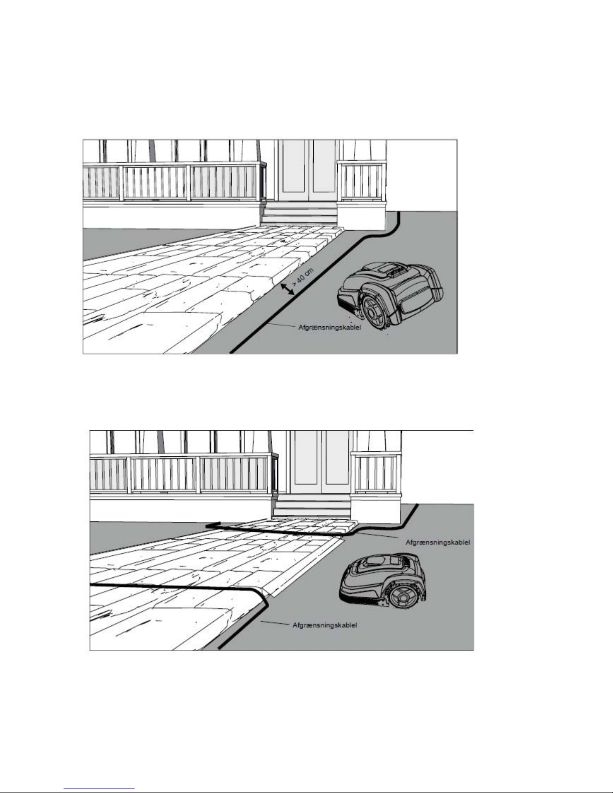
Stier, indkørsler og veje.
Ligger der et gang eller kørselsareal i robottens klippeområde, som er i et andet niveau
end græsplænen, bør det undgås , at robotten prøver at køre over dette areal for at komme
til græsset på den anden side. I stedet bør der lægg es afgræns ningskabel med 20-40 cm
afstand til gang arealet.
Hvis græsplænen og gang- og kørselsareal er i samme højde, kan man godt lade robotten
køre over arealet med hj æl p af afg ræ nsni ng s kabel e t . (se bi ll ede)
Page 22

22
Ujævn plæneoverflade
Har græsplænen en ujævn overflade, vil der være risiko for at skade på knivene, ved at de
rammer jorden.
Dette bør undgås helt for at sikre holdbarheden af robotplæneklipperen.
Udjævn klippearealet, fyld huller med jord. Er det ikke muligt at udjævne, bør dette areal
helt udelukkes fra klippeområdet med afgrænsningskabel.
Blomsterbede
Indeholder klippeområdet blomsterbede der skal beskyttes med afgrænsningskabel, er der
2 muligheder for dette, som følger her:
Ønsker man, at robotpl æ nekl i pp er en sk al følg e kablet rundt om blomsterbedet , når den
skal køre til ladestation, må kablet ikke ligge tættere end 10 cm. (Se billede)
Page 23

23
Ønsker man at robotten skal køre over de 2 paralle kabler, må de ikke ligge med større
afstand end 5 mm. Her vil det dog være nødvendigt at sætte en forhindring (sten, rør, evt.)
på position A (se billede) for at sikre, robotten, ikke bare kører rundt i ring.
Note: Position A skal være et fladt område og må ikke være på en skråning.
Omkring position A skal der være minimum 1x1 meter fladt område.
Husk, når afgrænsningskablet skal lægges rundt om blomsterbedene, er det vigtigt at
huske, på, hvordan blomster og planter ændre sig hen over året, så det på ethvert
tidspunkt af året, er plads til robotplæneklipperen kan passere bedet uden at beskadige
planterne.
Havebassin og swimmingpool s .
Robotplæneklipperen kan naturligvis ikke tåle at komme under vand.
Har havebassinet eller swimmingpoolen ikke en høj kant som på billedet, skal de
afgrænses via afgrænsningskabelet, eller alternativt opsætte hegn omkring disse.
Vælger man afgrænsning s kabel til at beskytte disse, er det vigtigt at afstanden til
vandkanten øges fra de normal 20-30 cm til 1 meter, for at forhindre robotten skrider ud
over kanten i vådt vejr.
Page 24

24
Bemærk
Når forhindringer skal afgrænses med afgrænsningskablet, er det vigtigt at kablet ikke
krydser hinanden, da robotplæneklipperen ikke vil kunne følge den rigtige retning, hvis det
krydser.
Korridor
Har klippeområdet en korridor, er der visse mål, der skal overholdes for at
robotplæneklipperen kører optimalt.
Længden må max. være 8 meter og minimum 2 meter bred.
Skulle korridoren være længere end 8 meter eller smallere end 2 meter, kan robotten ikke
køre der, og dette område skal fjernes fra klippeområdet ved hjælp af afgrænsningskablet.
Page 25

25
Markering og placering af robotplæneklipperens arbejds om rådet
Nu har du fået en grundlæggende introduktion til, hvordan de basale principper for TEXAS
Robotplæneklipperen fungerer.
Næste skridt er at lægge afgrænsningskablet, og den skitse f or din have, som tidligere er
beskrevet under kapitlet ”Installationsguide – introduktion.”
Dette er en meget vigtigt del af installationen, og derfor er det yderst vigtigt at følge ens
skitse og få lagt kablet helt korrekt, da dette ellers vil give mange problemer fremadrettet.
Afgrænsningskablet skal være forbundet i et sammenhængende kabel uden br ud el ler
krydsninger på afgrænsningskablet. Dette samles til sidst i ladestationen.
Page 26

26
Placering af la destation.
Placering af ladestationen kræver, der er 230 V. strømudtag i nærheden, hvor man ønsker
den skal placeres. Alternativt skal der trækkes et forlæng er kabel ud ti l den ønskede
position af ladestationen.
BEMÆRK: Det medfølgende strømkabel til ladestationen er 20 M.
VIGTIGT: Husk at beskytte 230V strømkablet ud til ladestationen, for at undgå skader på
strømkablet, kortslutning eller elektrisk stød.
Ladestationen skal placeres på et fladt underlag og skal have minimum en lige strækning
på 2 meter foran ladestationen, for at sikre robotplæneklipperen får den rigtige indkørsel til
laderen. Det er vigtigt, at dette overholdes.
Ligeledes skal der være 1 meter fri plads på siderne af ladestationen også for at sikre
korrekt indkørsel til lader.
VIGTIGT: Når robotten kører hjem for at lade op, kører den altid mod uret hjem. Derfor
skal ladestationen placeres som på billedet nedenfor.
Page 27

27
Er ens græsplæne/jord foran ladestationen blød eller begyndt at blive opkørt i forbindelse
med robottens ind og udkørsel fra lade statioen, anbefales det, at der lægges en
plastplade eller gummimåtte foran indkørslen til ladestation.
Forkert opstilling:
Ladestationens placering må kun være på max 5° hældning sideværts.
Når du har fundet den korrekte placering, og ladestationen er opsat må strømmen IKKE
tilsluttes endnu. Først skal afgrænsningskablet udlægges, og tilsluttes ladestation. Derefter
kan strømmen tilsluttes.
Page 28

28
Udlægning af afgrænsningska be l.
Nu skal afgrænsningskablet lægges. Find først pakken med kabel (del 19) og find den l øse
ende.
Find nu plast pløkkerne (del 15). Den medfølgende lineal (del 17) skal også findes frem og
bruges.
Derudover skal bruges en hammer, en klemmetang og en tang/saks til at klippe ledning
med. (Dette medfølger ikke)
Husk græsset ikke må være højere end 60 mm. inden arbejdet påbegyndes, ellers skal det
først klippes med en almindelige plæneklipper.
Start kabellægningen ved ladestationen. Træk ca. 1 meter kabel ud, så du har rigeligt med
kabel at arbejde med, når det skal tilsluttes i strømstikkene på ladestationen.
Læg afgrænsningskablet på græsset og sæt det løsligt fast med plast pløkkerne. (Det er
ikke nødvendigt at grave kablet ned i jorden. Inden længe er kablet vokset ind i græsset og
ses ikke)
HUSK: Hold 20-30 cm afstand til græskanten/forhindringer. Brug den medfølgende lineal
(del 17)
Jo tættere på jorden kablet lægges, jo mindre risiko er der, for man falder over kablet , el ler
det skulle blive klippet over af robotten. Strømstyrken i afgrænsningskablet er kun 32V og
derfor ingen fare for hverken me nnesker eller dyr.
Afgrænsningskablet lægges nu løsligt rundt i haven efter din have skitse. Læg kablet
løsligt, så er det nemmere at rette på kablet undervejs.
Sæt plastpløkkerne for hver ca. 50-80 cm alt efter om det er en lige strækning eller om det
er ved hjørner eller buer.
Page 29

29
Sørg for at kablet sider korrekt i plast pløkken (Se billede)
Når du kommer til et hjørne i din have, er det her vigtigt, at kablet drejer i en blød bue og
ikke følger hjørnet i en 90° vinkel.
Page 30

30
Ved forhindringer der skal afgrænses, er det vigtigt at følge den retning, man er startet fra.
(Se billede)
HUSK: Afgrænsningskablet må IKKE krydse sig selv på noget tidspunkt.
Nu når du har udlagt afgrænsningskablet, overholdt alle afstandsmål nøje, og du er tilfreds
med den måde kablet er lagt i din have, så er det tid til at fastgøre pløkkerne.
Tag din hammer og slå nu plastpløkker ordentligt fast i jorden. Sørg for at holde kablet helt
stramt, når pløkkerne slås fast, så kablet ligget helt lige.
Skulle du løbe tør for afgrænsningskabel, kan ekstra kabel købes hos din TEXAS
forhandler eller på www.texas.dk (Varenr: 431752, 200m)
Skal der bruges ekstra kabel, eller bliver afgrænsningskablet revet over og skal samles,
brug da de medfølgende kabelforbinder (del 18).
Afisolér kablet (skræl plastikken af kablet) ca. 1,5 cm af enderne. Stik de blottede
kabeltråde ind i kabelforbinderen, og klem kabelforbinderen sammen, til der kommer et
klik. Så er kablet forbundet igen.
Når du er nået tilbage til ladestationen træk da igen ca. 1 meter ekstra kabel ud, så der er
rigelig kabel at arbejde med ved tilslutning.
Page 31

31
Forbind afgrænsningskablet til ladestationen
Nu skal afgrænsningskablet forbindes i ladestationen.
HUSK: Der skal være minimum 2 meter kabel i en lige strækning ud fra ladestationens
køreplade.
Det er vigtigt at lægge kablet fra fronten, ind under kørepladen, og trække det ud ved
bagenden af ladestationen. Tilpas længden af kablet, klip overskydende kabel væk.
Af isolér kablet (skræl plastikken af kablet) ca. 1,5 cm af enderne. Brug en af isolering
tang, eller en kniv. Pas på fingrene!
Tvist metal trådene fra kablet, så kabel enden bliver stram.
Nu er afgrænsningskablet klar til montering.
Se billede, dette beskriver, hvordan kablerne skal monteres på ladestationen.
Det kabel der går ind til ladestationen bag fra (A), skal fastgøres i ”+” elstikket.
Kablet der kommer ind forfra (B), skal monteres i ”S1” eller ”S2” elstikket.
Normalvis er det valgfrit om der vælges S1 eller S2, men har din nabo også en TEXAS
robotplæneklipper, skal der vælges det modsatte elstik indgang, end den indgang naboen
bruger.(Læs afsnittet ”Klippebegrænsninger for TEXAS Robotplæneklipper”)
Når afgrænsningskablet er korrekt monteret i ladestationen, skal den fastgøres med 4
plast pløkker, for at sikre ladestationen ikke forskyder sig, med kabelskade tilfølge.
Nu kan 230V strømmen tilsluttes til ladestationen.
Page 32

32
Nu lyser en lille LED diode. Lyser dioden BLÅ er alt OK, og der er forbindelse i
afgrænsningskablet.
Er der ikke noget lys i dioden, tjek da først 230V strøm forbindelse, om den er opsat
korrekt.
Hvis LED dioden ikke konstant lyser BLÅ, og der ikke er fejl i 230V forbindelsen, tjek da
følgende fejlsøgningsskemaet.
LED
BESKRIVELSE
1
Blåt lys
Normal
2
Blåt lys blinker, rød slukket
Intert kabelbrud i ladestation, afgrænsingskabel ok.
Tjek kabel på undersiden af ladestation.
3
Rødt lys blinker, blåt slukket
Brud på afgrænsningskabel, ladestations kabel ok.
Tjek evt. kabel samlinger. Tjek ladestationsens
kabelindgang.
4
Rødt og blåt lys blinker
Afgrænsningskabel og i nter nt ladestations kabel, brudt eller
kortsluttet.
Tjek evt. kabel samlinger. Tjek ladestationsens
kabelindgang.
Opstart og test af installationen.
Når LED dioden konstant lyser blåt, er det tid til at afprøve robotplæneklipperen.
Løft robotten op, og tænd den på hovedafbryderen
Page 33

33
Stil nu robotten et tilfældigt sted på klippeområdet. Tryk på STOP knappen på toppen af
robotten.
Nu åbnes top coveret af sig selv.
Tryk PIN koden ind. Koden vil være 0000, som er indstillet fra fabrikken. (Senere kan
personlig PIN kode indstilles, læs kapitlet ”PIN kode”)
Find knappen ”HOME” og tryk på den, derefter skal top coveret manualt lukkes.
Nu vil robotten starte med at køre. Den vil selv finde hjem til ladestationen, ved at finde ud
til afgrænsningskablet, og køre mod uret hjem. Her vil den begynde at lade batteriet helt
op.
Skulle det ske robotten ikke rammer ladestationen eller påkører den skævt, skal
ladestationens placering sandsynligvis lige tilrettes.
Nu vil robotten automatisk begynde og lade op, og følgend e symboler vil blinke i displayet,
indtil den er helt opladet.
Programmering
VIGTIGT: Start med at indstil le tid og dato, da det er grundlaget for alt
programmering!
For at starte programmering af robotplæneklipperen skal den være færdig med at oplade.
Nu skal STOP knappen aktiveres, så top coveret åbnes og programmering kan begynde.
Fra fabrikkens side, har robotten en standard progr ammer i ng , som f or de fles te havers
vedkomne vil kunne bruges. Men det anbefales at sætte sig ind i det, for at få en bedre
forståelse af robotten, og naturligvis ændre opsætning.
Page 34

34
Sådan her ser displayet ud:
BEMÆRK: Skærmen er en touch screen. (Berøringsskærm)
Beskrivelse af knapperne:
Retningsknap: For hvert tryk vil cursoren bevæge sig op eller til venstre.
Retningsknap: For hvert tryk vil cursoren bevæge sig ned eller til højre.
SET Knap: Fungere som en ”Enter” knap eller for at starte justering af maskinen
indstillinger.
Page 35

35
HOME Knap: Robotplæneklipperen vil automatisk vende tilbage til ladestation, når denne
knap aktiveres.
Start Knap: Robotplæneklipperen vil starte dens, klippecyklus.
Overblik over touch skærmen.
Skærmen er inddelt i flere forskellige zoner
Zone 1: Dato område.
Zone 2: Tidsområde. Hvis fejlkoder opstår, vises de også her.
Zone 3: Arbejdsdage, og numerisk keybord til PIN indtastning.
Zone 4: Maskines status display
Zone 5: Ladestatus.
Zone 6: Arbejdstids område.
Zone 7: Klippedisplay, og PIN kode visning.
Page 36

36
Forklaring af symboler på touc h s kær m
Kraftigt si gnal. Robotten funkgere normalt.
Svagt signal. Robotten fungere normalt .
Blinker! Betyder ”Intet signal”. Robotten stopper med at klippe. (Se proble mlø sni ng )
Blinker! Betyder ”Uden for klippeområde”. Robotten vil stoppe med at klippe.
(Se problemløsning)
Blinker! Når robotten bliver løftet, vises dette symbol i displayet.
BEMÆRK: Symbolet kan også blive aktiveret ved vibrationer under kørsel.
Er løfte sensoren aktiveret mindre end 1 sekund, vil robotten automatisk vende tilbage til
normal klippecyklus.
Er sensoren aktiveret mere end 1 sekund og under 8 sekunder vil robotten stoppe op, og
automatisk genstarte.
Er sensoren aktiveret mere end 8 sekunder låser robotten automatisk a nti-tyveri
funktionen, og skal låses op med PIN kode.
100% opladet 75% kapacitet 50% kapacitet 30% kapacitet Afladet
Page 37

37
Vises vedvarende: Vender hjem til ladestation for at lade op.
Blinker: Opladning igangværende
Blinker: Vises vedvarende: Vises når robotten er helt opladet i ladestationen, og
færdig med at lade.
Touch skærm er låst.
Indtast PIN kode. Skræm låses op.
Skift PIN kode. Indtast ny kode
Skift PIN kode. Indtast PIN kode igen
Afgrænsningskabel signal S1, er valgt.
Page 38
38
Afgrænsningskabel signal S2, er valgt.
STOP knappen er aktiveret. Robotten stopper med at klipper.
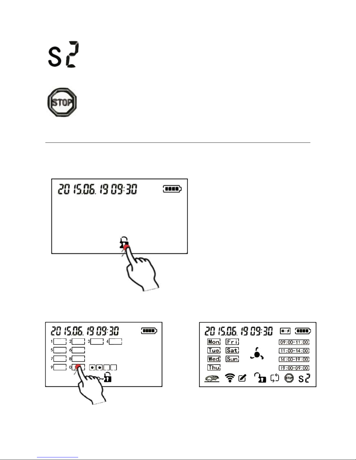
Indstilling af tid og dato.
Det er vigtigt, at tid og dato bliver indstillet, så den fremtidige klippeplan bliver korrekt.
Start med at trykke på STOP knappen, så top coveret åbnes.
Nu vises dette skærm billede:
Tryk på hængelås logoet for at låse den op.
Robotten er fabrikspro grammeret med en PIN kode, denne er 0000.
Indtast koden som vist her:
Page 39

39
Tryk på ”0” fire gange, derefter vil robotten låses op. Nu vil den normale startskærm vises.
Nu kan tidsindstilling begyndes.
Tryk på ”SET” knappen, i venstre side, derefter knappen.
Dato og tid vil nu begynde at blinke. Indstil år og dato ved at trykke på
Når det korrekte år og dato er valgt, trykkes der på ”SET” knappen.
Ryk videre til tidsindstilling, og følg samme instruktion som ved års og dato indstilling.
Når både dato og tid er indstillet korrekt, vent da i 15 sekunder, eller tryk et tilfældigt sted
på touch skærmen, og indstillingerne vil blive afsluttet.
Page 40

40
Klippecyklus indstilling
TEXAS’ robotplæneklipper kan indstilles til at have forskellige klippeprogrammer alt efter
hvad man ønsker, og alt efter størrelse på klippeområdet.
I det følgende gennemgås hvordan den klippecyklus indstilles.
Først og fremmest skal du vide ca. hvor mange kvadrat meter dit klippeområde er.
Følg tabellen her, for at se hvad der anbefales for de forskellige klippeområder.
Ex. Har du 600 m2 klippeområde skal du vælge 5 times klippetid pr. dag, ved at vælge
09.00-11.00 og 11.00-14.0 0, el l er 14.00-19.00. Det er helt op til forbrugeren hvilke
tidspunkt man ønsker den skal køre.
BEMÆRK: Ønsker man fx at robotten ikke skal køre i weekend dagene, skal klippetiderne
for de 2 dage, spredes ud over resten af dagene, for at sikre robotten kan nå at passe hele
klippeområdet.
Page 41

41
Sådan vælges klippedage og tidspunkt:
Tryk på de dage du ønsker robotten skal klippe. Når der er en sort firkant rundt om dagen
eller tidspunktet, betyder det at den dag og tid er valgt, og robotten vil klippe på det
tidspunkt.
Indstil kabelsignal.
Som tidligere beskrevet har robotplæneplæneklipperen 2 signaler. S1 og S2.
Tjek hvilken signal indgang der er valgt ved opsætning af ladestation.
Page 42

42
Denne signal indgang skal også vælges på touch skærmen.
Græsklipning
Når alle ovenstående instrukser er udført, er robotten klar til at klippe græsset.
Tryk på ”START” knappen, og luk top coveret.
Derefter vil klippe displayet begynde at rotere, og robotten køre ud og slå græs
Page 43

43
Opladning
Robotplæneklipperen finder selv tilbage til ladestationen når den har brug for strøm.
Den vil automatisk begynde at lade, når den holder stille i ladestationen.
Dette symbol vil blinke.
Batteri logoet vil blinke skiftende mellem disse:
Du kan til hver en tid trykke på ”HOME” knappen, hvis du vil have robotten væk fra
klippeområdet.
Tryk på HOME og luk top coveret. Den vil nu søge ud til afgrænsningskablet, og køre i
ladestation.
Skulle der være mere end 40° varme ved ladestationen, vil den stoppe med at lade for at
beskytte batteriet, og automatisk starte op igen når temperaturen er under 40° varme.
Lås og oplåsning af skærm
Hvis du ønsker at stoppe klipningen, men stadig holde batteriet aktivt, kan du låse
startskærmen og evt. sætte den tilbage til ladestationen eller lade den stå på
klippeområdet.
Det er simpelt at låse skærmen.
Tryk på hængelåsen midt på skærmen:
Nu er skærmen låst, og ligeledes er ”HOME”, ”START” og piletasterne også låst.
Midt på skærmen vises en LÅST hængelås.
Oplåsning.
Tryk på den låste hængelås, på skærmen. Tryk da PIN koden. Nu er skærmen igen oplåst.
Page 44

44
Ændring af PIN-kode
Fra fabrikken siden, er robotten standart indstillet til en PIN kode på ”0000”.
Det anbefales kraftigt, at ændre koden til en personlig kode for sikkerhedens skyld.
Sådan gør du:
Tryk ”STOP” knappen, så top coveret åbn er s i g .
Tryk på knappen og hold den inde, derefter knappen og hold den inde. Til
slut, tryk nu på ”SET” knappen, og hold den inde, i ca. 8-10 sekunder.
BEMÆRK: Alle 3 knapper skal holdes nede samtidig, før det virker.
Nu skifter skærmen til PIN kode skærmen.
Indtast den gamle PIN kode.
Page 45

45
Indtast den nye PIN kode når dette logo vises:
Derefter skal den nye PIN kode igen indtastes når dette logo vises:
Når robotten har registreret at, den nye PIN kode er indtastet 2 gange, vil denne nye kode
træde i kraft.
Indtast nu den nye PIN kode, og robotten er igen klar til brug.
Fejlikoner.
Finder du din robot, holdende stille på klippeområdet, vil der være sket en fejl.
Tryk på STOP knappen og se hvilket symbol der blinker.
Intet signal. Kontroller hvilken farve LED dioden i ladestationen har. (Se ”Fej ls ø g ni ng ” )
Løftet. Indtast PIN koden, og prøv at starte robotten igen.
Batteri tomt. Sæt robotten hen i ladestationen.
Page 46
46
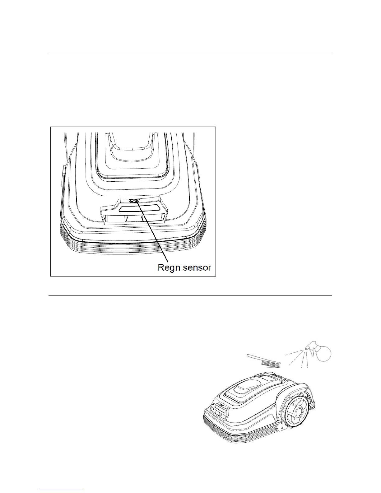
Regnsensor
Græsslåning i regnvejr anbefales ikke.
TEXAS robotplæneklipperen har indbygget regnsensor, som stopper robotten i regnvejr.
Robotten kører selv hjem til ladestationen, når regnsensoren bliver aktiveret.
Herefter vil robotten lade helt op. Derudover vil den blive holdende i ladestation yderligere
2 timer. Først derefter vil robotten forsøge at køre ud igen, og starte klipning. Skulle det
stadig være regnvejr, køre den tilbage til ladestation igen.
VIGTIGT: Kortslut ikke de to regnsensor poler.
Rengøring og udskiftni ng af res er vede l e
Det er vigtigt at holde din robotplæneklipper ren for at forlænge dens levetid.
Robotten vil nemmere kunne klare skråninger hvis hjulene er rene og i orden. Ligeledes
bliver klipperesultatet meget pænere, når knivene er skarpe og i orden. (Sluk altid på
hovedafbryderknappen, når der arbejdes med knivene)
Rengøring af plast skjolde.
Der må ikke skylles med vandslange eller
højtryksrenser på robotten for at beskytte
elektronikken og batteriet i
robotplæneklipperen.
Det anbefales at bruge en blød børste til at
fjerne græs og andet skidt. Evt. en
vandforstøver til at opløse skidt.
Rengøring af undersiden.
Brug arbejdshandsker for sikkerhedens skyld!
Page 47

47
Mindst en gang om ugen, gerne mere, vil
det være nødvendigt at rengøre
robotplæneklipper en p å under si de n og
især ved knivene.
Husk, at starte med at slukke på
hovedafbryderknappen.
Læg robotten om på siden.
Brug en blød børste til rense for græs for
at sikre et godt klipperesultat. Det
reducerer også klippestøj.
1: Tjek at knivholderen kan rotere frit.
2: Tjek at knivene kan rotere frit.
3: Tjek at forhjulene kan dreje og rotere
frit.
Rengøring af ladestation.
Ligesom robotten jævnligt skal rengøres, er det en god ide i samme omgang at rengøre
ladestationen.
Fjern græs og jord på kørepladen.
Engang hver 2. måned ca., bør ladekontakterne på ladestationen(1) og robotten (2)
rengøres.
Brug noget fint slibepapir eller stål uld til at fjerne evt. rust eller iring på lade stikkene.
Knivbladene.
Knivene har to skarpslebne sider. Derfor kan de vendes, når de er blevet uskarpe på den
ene side.
Knivbladene kan let skiftes. Det krævet blot en stjerneskruetrækker. (Sluk på
hovedafbryderknappen, når der arbejdes med knivbladene)
Skru skruen ud, fjern snavs og græsrester på knivholderen. Erstat knivbladet med et ny t.
(Varenummer: 431661). Sørg for knivskruerne er strammet godt.
Bemærk: Alle 3 knive skal vendes eller skiftes samtidig for at undgå ubalance.
2
1
Page 48

48
Udskiftning af batteriet .
Batteriets levetid afhænger af arbejdsbelastning, vedligeholdelse og vinteropbevaring.
Under normale vilkår vil levetiden være op til 5 år.
Batteriet udskiftes let.
1. Skru klippehøjden ned til laveste klippehøjde.
2. Skru de 5 skruer ud, der holder låget til batterikammeret.
3. Tag batteriet ud med et fast greb.
Page 49

49
Problemløsning for ladestation
LED
BESKRIVELSE
1
Blåt lys
Normal
2
Blåt lys blinker, rød slukket
Intern kabelbrud i ladestation, afgrænsingskabel ok.
Tjek kabel på undersiden af ladestation.
3
Rødt lys blinker, blåt slukket
Brud på afgrænsningskabel, ladestationskabel ok.
Tjek evt. kabel samlinger. Tjek ladestationsens kabel
indgang.
4
Rødt og blåt lys blinker
Afgrænsningskabel og i nter nt ladestationskabeler, brudt eller
kortsluttet.
Tjek evt. kabel samlinger. Tjek ladestationsens kabelets
indgang.
Problemløsning for robotplæneklipper
Nr.
Meddelelse
Meddelelses type
Symptom
Løsning
1
-
-
Blank skærm
1. Tjek hovedafbryderknappen
er tændt.
2. Første gang robotten skal
bruges, kan batteriet være
afladet. Sæt den til
opladning i ladestation.
2
-
-
Robotten kan ikke
ramme ind i
ladestationen.
1. Tjek afgrænsningskablet
foran kørepladen, er lagt
lige ud
2. Tjek ladestationen er
placeret i henhold til kapitlet
”Placering af ladestation”
3
-
-
Robotten kører
rundt i cirkler, ved
tilbagekørsel til
ladestation.
1. Tjek 230V strømkablet
ligger for tæt på
afgrænsningskablet. Flyt
230V kablet længere væk
fra afgrænsningskablet
4
Blinker
-
Robotten er i gang
med at lade op.
1. Normal funktion.
5
Lyser
vedvarende
-
Robotten kører
tilbage mod
ladestation.
1. Normal funktion
6 Advarsels
meddelelse
Batteri volt, er for
lav til at robotten
kan funkgere.
1. Når batteriet er lavt, vil
robotten normalvis selv
køre tilbage til ladestation.
2. Hvis ikke, løft da robotten til
ladestationen og lad den
op.
7 Advarsels
meddelelse
Robotten har været
løftet, under
klipning.
1. Tjek om græsset er højere
end 60 mm.
2. Tjek robotten for
fremmedlegemer, der har
aktiveret løfte sensoren.
Page 50

50
8 Advarsels
meddelelse
Robotten kan ikke
modtage signal fra
afgrænsningskablet
1. Tjek om ladestationens
LED diode lyser blåt.
2. Tjek, om 230V er
forbundet, hvis LED
diode ikke lyser.
3. Hvis den lyser rødt, tjek
da om
afgræsningskablet er
korrekt monteret til
ladestation.
4. Hvis det er første gang
robotten bruges efter,
230V strøm har været
taget fra, bær da
robotten ud i nærheden
af afgrænsningskablet.
5. Tjek at signal indgang i
ladestation (S1 el. S2)
er det samme i
robotdisplayet.
9 Advarsels
meddelelse
Robotten er eller
har været uden for
afgrænsningskablet.
1. Er robotten inden for
afgrænsningskablet,
tjek om kablerne er
korrekt monteret til
ladestation.
2. Er robotten uden for
området, løft den da ind
i området igen og
genstart robotten.
3. Kører robotten ud af
området i et hjørne,
sørg da for at hjørnet
ikke er mere end 90°
vinkel.
4. Kører robotten ud af
området gentagne
gange samme sted, tjek
da om der ligger et
230V strømkabel i
nærheden eller
nedgravet.
Hvis det er tilfældet, bør
dette området undgås
ved at flytte
afgrænsningskablet.
10
Knivene kører
rundt.
1. Normal funktion
Page 51

51
Fejlkoder.
Nr.
Meddelelse
Meddelelses
type
Symptom
Løsning
1
EF 01
Advarsels
meddelelse
Betyder
forhindringssensor
sidder fast.
Tjek om det sidder
fremmedlegemer fast på
undersiden af robotten.
2
EF 02
Advarsels
meddelelse
Robotten har været
væltet.
Tjek om skråninger er for stejle,
eller for våde til at kører op ad.
Evt. bør området undgås, ved
flytning af afgrænsningskabel.
3
EF 03
Advarsels
meddelelse
Denne besked vises
kun i fejl menuen.
Robotten har været
væltet.
Bær robotten til et fladt område
og genstart den.
4
EF 04
Advarsels
meddelelse
Robotten er
fanget/sidder fast.
Har forhindringssensoren været
udløst 10 gange inden for et
minut, kommer denne
meddelelse.
Tjek om robotten sidder fast
mellem træer eller andet.
5
EF 05
Advarsels
meddelelse
Robotten har været
løftet, under kørsel.
Tjek om græsset er højere end
60 mm.
Tjek robotten er fri for
fremmedlegemer.
6
EF 06
Advarsels
meddelelse
Robotten har været
uden for
afgrænsningskablet.
1. Er robotten inden
for
afgrænsningskablet,
tjek om kablerne er
korrekt monteret til
ladestation.
2. Er robotten uden for
området, løft den da
ind i området igen,
og genstart
robotten.
3. Kører robotten ud af
området i et hjørnet,
sørg da for at
hjørnet ikke er mere
end 90° vinkel.
4. Kører robotten ud af
området gentagne
gange samme sted,
tjek da om der
ligger et 230V
strømkabel i
nærheden eller
nedgravet.
Hvis det er tilfældet,
bør dette området
undgås, ved at flytte
afgrænsningskablet.
7
EF 07
Advarsels
meddelelse
Robotten kan ikke
modtage signal fra
afgrænsningskablet
1. Tjek om
ladestationens LED
diode lyser blåt.
Page 52

52
2. Tjek, om 230V er
forbundet, hvis LED
diode ikke lyser.
3. Hvis den lyser rødt,
tjek da om
afgræsningskablet
er korrekt monteret
til ladestation.
4. Hvis det er første
gang robotten
bruges efter, 230V
strøm har været
taget fra, bær da
robotten ud i
nærheden af
afgrænsningskablet.
5. Tjek at signal
indgang i
ladestation (S1 el.
S2) er det samme i
robotdisplayet.
8
EF 08
Advarsels
meddelelse
Batteri volt er for
lavt til at funkgere
normalt.
1. Når batteriet er lavt, vil
robotten normalvis selv
køre tilbage til
ladestation.
2. Hvis ikke, løft da
robotten til
ladestationen og lad
den op.
9
EF 09
Advarsels
meddelelse
Driv motor kan
været låst/
beskadiget
Afbryd strømmen på robotten,
og genstart den.
Opstår problemet stadig,
kontakt TEXAS forhandler.
10
EF 10
Advarsels
meddelelse
Klippemotor kan
været
låst/beskadiget
Afbryd strømmen på robotten,
og genstart den.
Opstår problemet stadig,
kontakt TEXAS forhandler.
Page 53

Smart G-Force SB900, SB1200
Texas A/S - Knullen 22 - 5260 Odense S - Denmark Version 17.1
Tel. +45 6395 5555 - www.texas.dk - post@texas.dk
GB User Manual
Page 54

2
Contents “Original User Manual”
Package content ................................................................................................................... 3
Description of TEXAS robot lawnmower ............................................................................... 4
Technical data ...................................................................................................................... 5
Safety symbols ..................................................................................................................... 6
Safety instructions ................................................................................................................ 7
Maintenance and storage during the winter ......................................................................... 9
Preparation for the spring .................................................................................................. 10
Handling the robot lawnmower .......................................................................................... 10
Lightning protection ........................................................................................................... 11
Basic functional principles for the TEXAS Robot Lawnmower ............................................. 12
Detecting the boundary cable ............................................................................................ 14
Starting and stopping mowing ........................................................................................... 15
Mowing limits of the TEXAS Robot Law nm ower ................................................................. 15
Setting the mowing height ................................................................................................. 16
Installation guide ............................................................................................................... 17
Marking out and positioning of the robot lawnmower’s working area ................................ 25
Positioning of charging station ........................................................................................... 26
Laying out the charging station .......................................................................................... 28
Connecting the boundary cable to the charging station ..................................................... 31
Start-up and test of installation .......................................................................................... 33
Programming ...................................................................................................................... 34
Explanation of symbols on the to uchscreen ....................................................................... 36
Entering the time and date ................................................................................................ 38
Mowing cycle setting .......................................................................................................... 41
Mowing ............................................................................................................................... 43
Charging ............................................................................................................................. 44
Locking and unlocking the screen ...................................................................................... 44
Changing the PIN code ...................................................................................................... 45
Rain sensor ........................................................................................................................ 47
Cleaning and replacing spare parts .................................................................................... 48
Replacing the battery ......................................................................................................... 50
Charging station troubleshooting ....................................................................................... 50
Robot lawnmower troubleshooting ..................................................................................... 51
Error codes ......................................................................................................................... 53
Page 55
3
Package content
(Product number : 431757) (Product number: 431756) (Product number: 431758) (Product number: 431752)
Robot lawnmower
Charging station
Power supply
Power supply cable
Boundary cable collector
Plastic pegs
Extra Blade
Boundary cable
Manual
Ruler
Operating Manual
Page 56

4
Description of TEXAS robot lawnmower
Thank you for purchasing a TEXAS robot lawnmower.
On the next few pages pages the manual and its illustrations will explain in detail the
design and function of the robot lawnmower and charging station.
1 Robot lawnmower
11 Main switch
2 Stop button
12 Display
3 Display and touchscreen
13 Power supply
4 Charging point
14 Cable extension
5 Charging station
15 Plastic pegs
6 Blades (qty. 3)
16 Rain sensor
7 Blade holder
17 Ruler
8 Front wheels
18 Boundary cable collector
9 Rear wheels
19 Boundary cable
10 Carrying handle
Page 57

5
Technical data
Type no.
90070200
90070201
Product
Smart G-force SB900
G-force SB1200
Engine specifications
Motor model
Battery
Battery
Motor type
24 V, 2.0 Ah
24 V, 2.9 Ah
Power
50 W
50 W
Drive system
Cutting time per charge
45 minutes
60 minutes
Capacity
900 m3
1200 m3
Charging time
70 minutes
70 minutes
Operating speed
0.4 m/s
0.4 m/s
Machine
Working width
18 cm
18 cm
Multi-mowing
Yes
Yes
Blade system
Qty. 3 Floating
Qty. 3 Floating
Working height min. – max.
20–60 mm
20–60 mm
Working height settings
5
5
Height adjustment
Central
Central
Mower cover
Plastic
Plastic
Lift sensor
Yes
Yes
Obstacle sensor
Yes
Yes
Tipped over sensor
Yes
Yes
Tilt sensor
Yes
Yes
Rain sensor
Yes
Yes
Incline
40%
40%
Multi-working area
1
1
Equipment
Boundary cable
150 m
150 m
Pegs
Qty. 150
Qty. 150
Extra Blade
6
6
Charging station
1
1
Touchscreen
Yes
Yes
Dimensions
Mower size (L x B x H)
570 x 390 x 260 mm
570 x 390 x 260 mm
Weight
8.5 kg
8.5 kg
Emissions data
LpA sound pressure level
46 dB
46 dB
LwA uncertainty factor
0.35 dB
0.35 dB
LwA guaranteed noise level
67 dB
67 dB
Page 58

6
Safety symbols
Warning! The machine can be hazardous if used recklessly or incorrectly
and this can lead to serious injury or potentially fatal injury in some cases.
Therefore, it is important that you read and understand the user manual.
Read the user manual before use.
Stay clear of the robot lawnmower when it is operating.
Keep hands and feet clear of the rotating blades. Never put hands or feet
close to or under the robot lawnmower when it is operating.
Ensure that the main switch is in the OFF position before carrying out
maintenance or inspection of the machine.
Never sit on the machine.
The battery in the robot lawnmower is a Li-ion battery.
The battery may not be disposed off in ordinary household waste.
The battery must be disposed of at a recycling centre.
The robot lawnmower may not be dipped or thrown into water.
Never expose the robot lawnmower to fire.
Never expose the battery to strong sunlight for longer periods of time or
temperatures that exceed max. 45 °C.
The robot lawnmower or charging station may not be disposed of with
ordinary household waste, because the products contain electronic
components.
The product must be taken to a recycling centres or other facility that
handles the recycling of electronics.
WARNING SYMBOLS ON THE CHARGING STATION.
Read the user manual before use.
Double insulated.
Cable orientation.
Page 59

7
Safety instructions
WARNING
Read all of the safety instructions and all of the other instructions.
When working with the robot lawnmower, always follow the safety instructions precisely.
Read the user manual thoroughly before you start to use the machine. Ensure that you
can immediately stop the machine in case of an accident.
Failure to follow the warnings and safety instructions may lead to electric shock, fire and
serious personal injuries.
The warnings, precautions and instructions that are written in this user manual can not
cover every condition or situation that may arise. The user must therefore use common
sense and exercise caution when using the machine.
Safety
• Read the instructions thoroughly and ensure that as the user, you understand all of the
instructions.
• Never allow people who are not familiar with the use of the robot lawnmower to operate
it and never allow children to operate it.
• Local restrictions may limit the age of the operator.
• The person who operates the machine, is responsible for the safety of other people
and their property in the working area.
Use of the machine
• Ensure that the boundary cable is fitted as shown in the manual.
• Regularly inspect the area where the machine is to be used and remove stones, sticks
and other material which could damage the robot lawnmower.
• Regularly inspect the blades and blade bolts and check whether any of the blades are
blunt or damaged. Replace worn or damaged blades or bolts if necessary to maintain
the balance.
• The machine may not be used for any other purpose than that described in the user
manual.
• Only use original accessories and original spare parts. Fitting non-approved parts can
result in an increased risk and is therefore illegal. All liability is disclaimed for damage
or accidents that are a result of the fitting of non-original parts.
• Never use force when using a tool. Use the correct tool for the task.
Page 60

8
In general
• Do not use the robot lawnmower if the plastic guards are not correctly fitted to the
machine.
• Do not place hands or feet in the vicinity of rotating parts.
• Do not hold or lift the robot lawnmower if a wheel or the mower engine is operating.
• First press the STOP button.
Set the robot lawnmower’s main switch to the OFF position before:
– Removing all types of dirt or a stuck items.
– Carrying out maintenance, cleaning or servicing of the robot lawnmower.
• Start the robot lawnmower according to the instructions. Once the main switch is in the
ON position, remember to keep hands and feet clear of rotating blades.
• Never lift or carry the robot lawnmower around when the main switch in the ON
position.
• Do not allow people to use the robot lawnmower if they do not know how it functions.
• Do not place anything on top of the robot lawnmower or on the charging station.
• Do not use the robot lawnmower if it has damaged blades, plastic guards, bolts,
screws, etc.
• Avoid operating the robot lawnmower on wet grass (it will require more cleaning).
• Once the mower is set to an automatic mowing cycle, the mower must be kept under
observation if there are animals, children or adults inside the robot’s moving area.
Main switch
Button pressed in = ON
Button pressed out = OFF
Page 61

9
Personal safety
• If the main switch is broken or does not work properly, the robot lawnmower may not
be used. To learn more, visit www.texas.dk.
• Always pay attention to what you are doing and use common sense when using the
robot lawnmower.
• Minors may not operate the machine.
• The machine may only be operated by people who are rested and well. The robot is not
to be used by anyone under the influence of alcohol, medicine or narcotic substances.
Maintenance and storage during the winter
• When storing the robot lawnmower during winter, it is recommended that the robot is
kept indoors in a dry and warm location and the main switch is set in the OFF position
to protect the battery.
Charge the battery in the robot
lawnmower using the accompanying
charging station before the robot is
stored away for the winter.
If it is not possible to keep the whole
robot indoors, the battery can also be
removed and stored indoors (must be
fully charged). (See picture).
The robot lawnmower’s battery is a
maintenance-free Lithium battery, with an
estimated lifetime of up to five years,
dependent on use, the surroundings and
winter weather conditions.
It is recommended that the charging
station is also kept indoors during the winter (do NOT remove the boundary cable).
• It is important that you charge the robot lawnmower 2-3 times during its winter storage
period to ensure that the battery is in a healthy condition. Take the robot lawnmower
out and put it in the charging station and let it charge up. Once charged, take the robot
back inside and leave in a warm and dry place.
Failure to follow these winter storage instructions will mean there is a risk that the
battery will lose capacity or cease to function.
• Check that all of the bolts, screws and nuts are tightened correctly, since this ensures
the best working conditions for the robot.
• Replace worn or damaged spare parts. Use only original spare parts.
• Clean the robot lawnmower thoroughly of dirt, grass, dust, etc. Pay attention to
ensuring the blade holder and wheels are clean, to avoid engine imbalance.
Page 62

10
Preparation for the spring
After the winter storage period has ended, it is advisable that you clean the charging
station and charging plates on the robot lawnmower using a steel brush or sandpaper.
This will improve the conducting connection when charging.
Handling the robot lawnmower
1. It is recommended that the robot lawnmower is transported in its original box when
transporting over longer distances.
2. When the robot shall be moved from the mowing area or its settings changed, the red
STOP button must be activated (see picture).
3. Once the STOP button is activated, the main switch must then be set to the OFF
position, before the robot is lifted up.
4. Lock the top cover and lift the robot using the handle designed for lifting the robot. Hold
the robot and blades away from the body to avoid injury.
Carrying handle
Page 63

11
Lightning protection
To protect the robot lawnmower from lightning strikes, it is recommended that it is not
placed in the charging station under or close to a high tree. It is also recommended that
the extension lead to the charging station is not wound around high trees.
It is recommended that the robot lawnmower does not operate during thunderstorms, so
as to avoid damage to the electric circuit components from lightning strikes. It is also
recommended that power is disconnected from the charging station and if possible, the
boundary cable is disconnected from the charging station.
Page 64

12
Basic functional principles for the TEXAS Robot Lawnmower
The robot lawnmower chooses its direction of travel randomly. In other words, it does not
move in accordance with some specific pattern but simply moves around the garden in a
random fashion. This has the advantage of ensuring that over a period of a week’s
mowing, the machine will have covered every part of the lawn within the boundary cable.
The user selects where and how they want to lay out the boundary cable in the garden.
The boundary cable determines the robot’s boundary.
The boundary cable is connected to the charging station, which sends a signal along the
boundary cable, which the robot lawnmower can sense via its front sensors.
Once the robot reaches the boundary cable, it will automatically stop, back up, turn around
and then continue in a new direction.
If the user has flower beds, trees, garden ponds etc., these can be protected by laying the
boundary cable around them.
The cable must form a circuit loop (see in detail under the section “Flower Beds”).
If during operation the robot lawnmower encounters an obstacle, people, animals, etc. it
will stop, back up, and continue in a new direction.
Page 65

13
If there is a corridor in the garden, which the robot lawnmower must drive along, the
corridor must be 2 m wide, with a max. length of 8 m.
The illustration below shows an example of a corridor, and how to lay out the boundary
cable.
Boundary cable.
As a safety precaution, the robot lawnmower is equipped with a lift sensor. This means
that the robot lawnmower will automatically stop the blades if the robot lawnmower is lifted
up.
Page 66

14
Moving to the charging station
After about 45 minutes operation, the robot lawnmower’s battery will need recharging (the
time depends om the height of the grass and the shape of the garden), and the robot
lawnmower will automatically find the nearest boundary cable and then automatically
(without mowing the grass) move in an anticlockwise direction back to the charging station.
It will dock with the charging station, charge up and then continued with the mowing cycle.
Detecting the boundary cable
When the robot lawnmower nears a boundary cable, the sensors installed on the front of
the cover will detect the boundary cable. But to ensure the best possible mowing result,
the robot will overlap the boundary cable by approx. 20–30 cm. It is important that the user
remembers this when laying out the boundary cable in the garden.
Page 67

15
Starting and stopping mowing
If you want to stop the robot lawnmower when it is mowing you must activate the STOP
button.
Once the STOP button is activated, the top cover will open and the robot will wait for a
command from the user. The robot lawnmower will not start again until the START button
is activated and the top cover is closed again.
Mowing limits of the TEXAS Robot Lawnmower
If both you and your neighbour have a TEXAS Robot Lawnmower, it is important that there
is at least 0.5 m between the boundary cables to avoid interference between the cable
signals.
In addition, it is also important that the charging station is set up at least 10 m from your
neighbour’s boundary cable.
The boundary cable must be connected to the charging station via either S1 or S2,
depending on what your neighbour’s connection is (learn more about this in the section
“Signal Setup”).
Page 68

16
If your neighbour has a robot lawnmower from another manufacturer, it may be necessary
to keep a distance of 2 m from your neighbour’s boundary cable to avoid interference.
The mowing area of the TEXAS Smart G-Force SB900 is up to 900 m2.
There is a limit to the maximum distance that the robot can be from the boundary cable.
It cannot be further than 22.5 m away from the boundary cable, otherwise the signal will be
too weak.
Setting the mowing height
The robot lawnmower’s mowing height can be set to 20–60 mm.
If the grass is higher than 60 mm, it will be necessary to mow the grass using a standard
lawnmower, otherwise the grass will cause too great a load for the robot’s blades and thus
lead to unsatisfactory mowing.
It can be a good idea to begin with by setting the mowing height to 60 mm and then
gradually lowering the mowing height, until you get the grass height that you desire.
The mowed grass height can be set by first pressing the STOP button, so that the top
cover opens.
The mowed grass height can be set by turning the selector (see image).
The robot lawnmower can mow wet grass, but this will lead to clumps of grass forming
under the robot, cause greater friction on the blades and generate extra noise.
However, you can easily remedy this by cleaning off the grass using a soft brush.
(ALWAYS set the main switch to the OFF position before working with the blades.)
Page 69

17
Installation guide
The following chapter explains how to install the TEXAS Robot Lawnmower.
Therefore, read this chapter thoroughly before planning and installing the boundary cable.
Introduction
It is recommended that you make a sketch of your lawn with the obstacles that you wish to
protect.
It will provide a good overview of the work in laying out the cable and for selecting the best
location for the charging station.
Draw the boundary cable from the charging station around the garden and around any
obstacles that you wish to protect, e.g. flower beds and trees.
Obstacles in the garden
Fixed obstacles in the garden that are higher than 100 mm, such as walls, hedges, garden
furniture, posts etc., do not need to be protected using the boundary cable, since the
robot’s obstacle sensors will register the encounter with the obstacle, enabling it to stop,
turn around and find a new direction of travel.
Page 70

18
Trees
The robot lawnmower will see most trees in the garden as ordinary ‘fixed’ obstacles and
therefore they do not need protection.
But certain trees, which are conical shaped at the ground in the form of exposed roots that
are lower than 100 mm, must be protected using boundary cable.
This is to avoid the robot moving over the roots and becoming stuck or damaging the
blades and undercarriage.
Rocks
If there are rocks in the robot’s moving area, it is important that you assess whether the
edge of the stone is higher than 100 mm, and whether the rocks require protection to avoid
damage to the robot.
Page 71

19
Slopes
The robot lawnmower can operate on inclines with a max. incline of 40% (27°).
If there is a direct descent to the boundary cable, the incline may not exceed 10° (17%) to
avoid the robot from moving across the cable if the grass is low friction.
If the robot lawnmower moves down against the boundary cable from an incline of more
than 10°, the boundary cable must be a minimum 2 m from the edge of the incline.
Inclines may not exceed
40% (27°)
Boundary cable
Max. incline, 10°
Boundary cable
Inclines greater than 10°
Page 72

20
Horizontal distance in cm Vertical distance in cm Incline in degrees
100
5
2.9
100
10
5.7
100
15
8.5
100
20
11.3
100
25
14
100
30
16.7
100
35
19.3
100
40
21.8
100
45
24.2
100
50
26.6
100
55
28.8
100
60
31
100
65
33
100
70
35
Page 73

21
Paths, driveways and roads
If there is a path or driving area in the robot’s moving area, which is at another level than
the lawn, the robot should be prevented from trying to move over this area to mow the
grass on the other side. Instead, a boundary cable should be laid down, 30 cm from the
area that people move around on.
If the lawn and path and driving area are on the same level, the robot can be allowed to
move across the area with help from the boundary cable (see picture).
Boundary cable
Boundary cable
Boundary cable
Page 74

22
Uneven lawns
If the lawn is uneven there will be a risk of the blades becoming damaged when they strike
the ground.
This should be avoided to ensure the long-term lifetime of the robot lawnmower.
In the case of uneven areas, hollows should be levelled out using soil. If it not possible to
level out the area, then the area should be cordoned off from the mowing area using
boundary cable.
Flower beds
If the mowing area contains flower beds, these should be protected using boundary cable.
There are two ways of doing this:
If you want the robot lawnmower to follow the cable around the flower bed, when it is to
move to the charging station, the cable must not be closer than 10 cm (see picture).
Page 75

23
If you want the robot to move across two parallel cables, they may not lie with a distance
that exceeds 5 mm. However, it will be necessary to place an obstacle (rock, pipe, if
required) on position A (see picture) to ensure that the robot does not just move around in
a circle.
Note: Position A must be a flat area and may not be an incline.
There must be a flat area of at least 1 x 1 m around position A.
Remember, when laying boundary cable around the flower beds, it is important to
remember how the flowers and plants change during the year, so that at all times there is
space for the robot lawnmower to pass by the flower bed without damaging the plants.
Garden ponds and swimming pools
Obviously, the robot lawnmower cannot be immersed in water.
If your garden pond or swimming pool does not have a high edge, as shown in the
illustration, it must be cordoned off using the boundary cable, or alternatively, a fence must
be installed around the pond or swimming pool.
If you choose to use boundary cable to protect your swimming pool, it is important that the
distance to the water edge is increased from the normal 30 cm to 1 m, to prevent the robot
from moving over the edge and falling into the water.
Pool
Page 76

24
NB
When obstacles must be cordoned off using boundary cable, it is important that the cable
does not cross over itself, because the robot lawnmower will not be able to follow the
correct direction if the boundary cable is crossed over.
Corridor
If the mowing area has a corridor, certain dimensions must be complied with, to ensure
that the robot lawnmower operates optimally.
The length may be max. 8 m and the width must be at least 2 m.
If the length of the corridor is longer than 8 m or narrower than 2 m, the robot cannot
operate there, and this area must be removed from the mowing area using the boundary
cable.
Ensure the boundary cable is not crossed
Max. length
of corridor
is 8 m
Minimum width of
the corridor is 2 m
Page 77

25
Marking out and positioning of the robot lawnmower’s working area
You have now been given a basic introduction into how the basic principles of the TEXAS
Robot Lawnmower function.
The next step is to lay out the boundary cable and the sketch for your garden, which was
previously described in the chapter “Installation guide - Introduction”.
This is a very important part of the installation, therefore, it is extremely important to follow
your sketch and lay the boundary cable completely correctly, otherwise many problems
may arise.
The boundary cable must be connected as a single cable, without breaks or crossing over
itself. It is finally connected to the charging station.
Page 78

26
Positioning of charging station
The positioning of charging station requires that there is a 230 V power outlet nearby.
Alternatively, you can connect an extension lead to the charging station.
NB: A 20 m power supply cable is included with the charging station.
IMPORTANT: Remember to protect the 230 V power supply cable out to the charging
station, so as to avoid damage to the power supply cable, short circuits or electric shocks.
The charging station must be positioned on a flat surface and there must be a straight
stretch of 2 m in front of the charging station to ensure that the robot lawnmower
approaches the charging station properly. It is important that this is observed.
There must also be 1 m free space at the sides of the charging station to ensure that the
robot lawnmower approaches the charging station properly.
IMPORTANT: When the robot returns to the charging station, it always moves in an
anticlockwise direction. Therefore, the charging station must be positioned as shown in the
illustration below.
Page 79

27
If the lawn/ground in front of the charging station is soft or has started to become torn up
because of the robot’s repeated docking and undocking, it is recommended that a plastic
panel or rubber mat is placed just in front of the charging station’s docking approach.
Incorrect setup
Page 80

28
The charging station may not be positioned on an incline that is greater than 5°.
Once you have found the correct positioning, and the charging station is setup, do NOT
connect power yet. First, the boundary cable must be laid out and connected to the
charging station. Power can then be connected to the charging station.
Laying out the charging station
The boundary cable must now be laid out. First, find the package with the cable (part 19)
and find the loose end.
Now find the plastic pegs (part 15). Find the accompanying ruler (part 17), which must also
be used.
You will also need a hammer, a pair of clamp pliers, and a pair of cutting pliers/scissors to
cut the lead with (not supplied).
NB: The grass may not be higher than 60 mm before the work begins. If it is higher than
this, then it must be mowed first using a traditional lawnmower.
Start laying the cable at the charging station. Pull out 1 m of cable so you have plenty of
cable to work with when connecting it to the power connectors on the charging station.
Lay the boundary cable on the lawn, and secure loosely using the plastic pegs (burying the
cable under the ground is not necessary. Before long the lawn will grow around the cable
and it will not visible).
REMEMBER: Keep a 30 cm distance between the boundary cable and obstacles. Use the
accompanying ruler (part 17).
The closer the cable is to the ground, the less risk of anyone tripping over it or of it
becoming cut by the robot. The power voltage in the boundary cable is only 32 V and
therefore, it is not hazardous to people or animals.
You can now loosely lay out the cable around the garden in accordance with your sketch.
Lay the cable loosely, because it will then be easier to correct the cable as you progress.
Set the plastic pegs about 50-80 cm apart, dependent on it is a straight section or whether
it is a corner or a curve.
Page 81

29
Ensure that the cable is fitted correctly in the pegs (see illustration).
When you come to a corner in your garden, it is important that the cable bend is less
sharp, and does not bend at 90°.
NO
OK
Page 82

30
If an obstacle is to be cordoned off, it is important that the cable follows the direction that
you started from (see illustration).
REMEMBER: The boundary cable must NOT cross over itself at any point.
Once you have laid out the boundary cable, check that the gaps have the precisely correct
lengths, and that you are satisfied with the way the cable is laid out in your garden. You
can now secure the cable using the pegs.
Take a hammer and now strike the pegs so that they are secure in the ground. Ensure that
the cable is completely taut when the pegs are struck into the ground, so that the cable lies
completely straight.
If you run out of boundary cable, you can purchase more cable at your TEXAS dealer or at
www.texas.dk (Product no.: 431752, 200 m)
If more cable needs to be purchased, or if the boundary cable is accidentally cut and
needs to be connected, use the accompanying cable connector (part 18).
Strip off about 1.5 cm of the insulation (strip off the plastic from the cable) from the cable
ends. Put the exposed cable wires into the cable connector and clamp the cable connector
together until you hear a click. The cable is now connected again.
When you have reached the charging station again, pull about another 1 m of extra cable,
to ensure that there is plenty of cable for the connection.
Page 83

31
Connecting the boundary cable to the charging station
The boundary cable shall now be connected to the charging station.
REMEMBER: There must be a minimum of 2 m of cable in a straight line opposite the
charging station’s docking panel.
It is important to lay the cable from the front, in below the docking panel and draw it out at
the rear of the charging station. Adjust the length of the cable, cut off the excess cable.
Strip off about 1.5 cm of the insulation (strip off the plastic from the cable) from the ends.
Use a wire stripper or a knife. Avoid cutting your fingers!
Twist the metal conductors from the cable, so that the ends become straight and taut.
The boundary cable is now ready to be connected.
See the illustration, which shows how the cables should be connected to the charging
station.
The cable that goes into the charging station from the rear (A), must be connected to the
“+” connector.
The cable that comes in from the front (B) must be connected to the “S1” or “S2”
connector.
Normally, it does not matter whether you use “S1” or “S2”. However, if your neighbour has
a TEXAS Robot Lawnmower, you must not choose the opposite input to the one your
neighbour chose, i.e. if your neighbour chose “S1” you must choose “S2” (read the section
“Mowing limits for TEXAS Robot Lawnmower”).
Page 84

32
Once the boundary cable has been correctly connected in the charging station, it must be
secured using the four pegs. This is to ensure that the charging station does not move and
cause damage to the cable.
The 230 V power supply can now be connected to the charging station.
A small LED will now light up. If the LED is BLUE, everything is OK and there is a
connection to the boundary cable.
If the LED does not come on, first check the 230 V power supply connection is correctly
setup.
If the LED does not switch on and remain blue all of the time, and there is nothing wrong
with the 230 V power supply connection, use the troubleshooting table to remedy the
problem.
LED
DESCRIPTION
1
Lit Blue
Normal
2
Flashing Blue, Red switched
off
Internal cable break in the charging station, boundary
cable OK.
Check the cable under the charging station.
3
Flashing Red, Blue switched
off
Break in the boundary cable, charging station cable
OK.
If required, check the cable connections. Check the
charging station’s cable input.
4
Flashing Red and Blue
Boundary cable and internal charging station cable,
break or short circuit.
If required, check the cable connections. Check the
charging station’s cable input.
Page 85

33
Start-up and test of installation
When the LED remains blue all of the time, it is time to try out the robot lawnmower.
Lift the robot up and set the main switch to ON.
Now place the robot on a random spot on the lawn. Press the STOP button on the top of
the robot.
The cover will open automatically.
Enter the PIN code. The code will be 0000, which is factory-set (you can enter a personal
pin code later on, read the chapter “PIN code”).
Find the “HOME” button and press it. You must then manually close the top cover.
The robot will start to move. It will find its way back to the charging station, by finding the
boundary cable, and then moving in an anticlockwise direction. It will dock with the
charging station and start to recharge the battery.
If the robot does not dock properly with the charging station or approaches it at an angle,
then most likely the docking station’s position will need to be adjusted.
Now the robot will automatically begin to charge up, and the following symbols will flash in
the display, until it is fully charged.
Main switch
Main switch
OFF
(Button pressed out)
ON
(Button pressed in)
Page 86

34
Programming
IMPORTANT: Start by setting the time and date, since it is the basis for
all other programming!
To start programming the robot lawnmower, it must have finished charging up.
Activate the STOP button, so that the top cover opens and you can start programming.
The robot is already programmed at the factory with a standard programme, which most
garden owners will be able to use. But it is recommended that you become familiar with
the programming to get a better understanding of the robot, and of course, so that you can
change the settings.
Display layout:
NB: The screen is a touchscreen.
Page 87

35
Description of the buttons:
Direction button: Press the button to move up or the left.
Direction button: Press the button to move up down or to the right.
SET button: Functions like an “Enter” button on a keyboard, or for starting the adjustment
of settings.
HOME button: The robot lawnmower will automatically return to the charging station when
this button is activated.
Start button: The robot lawnmower will start its mowing cycle.
Page 88

36
Touchscreen overview
The screen is divided into different zones.
Zone 1: Date area.
Zone 2: Time area. If an error code is generated, it will also be displayed here.
Zone 3: Working days, and numerical keyboard for entering the PIN code.
Zone 4: Machine status display.
Zone 5: Charging status.
Zone 6: Working time area.
Zone 7: Mowing display, and PIN code display.
Explanation of symbols on the touchscreen
Powerful signal. The robot is functioning normally.
Weak signal. The robot is functioning normally.
Flashing! This means there is ‘no signal’. The robot will stop mowing. (See troubleshooting
solution).
Zone 1
Zone 3
Zone 4
Zone 2
Zone 5
Zone 6
Zone 7
Page 89

37
Flashing! This means the robot is ‘Outside the mowing area’. The robot will stop mowing.
(See troubleshooting solution).
Flashing! When the robot is lifted, this symbol is shown in the display.
NB: The symbol can also be activated if the robot vibrates during operation.
If the lift sensor is activated for less than one second, the robot will automatically return to
its normal mowing cycle.
If the sensor is activated for longer than one second, and less than eight seconds, the
robot will stop and automatically restart.
If the sensor is activated for longer than eight seconds, the robot will automatically activate
its anti-theft function, and may only be unlocked using the PIN code.
100% charged 75% capacity 50% capacity 30% capacity Discharged
Shown continuously: Returning to the charging station to charge up.
Flashing: Charging underway
Flashing: Shown continuously: Is shown when the robot is completely charged in the
charging station, and finished charging.
Page 90

38
Touchscreen is locked.
Enter PIN code. The screen will unlock.
Change PIN code. Enter new code
Change PIN code. Enter PIN code again.
Boundary cable signal S1 is selected.
Boundary cable signal S2 is selected.
The STOP button is activated. The robot will stop mowing.
Entering the time and date
It is important that the time and date are entered, so that future mowing plans are correct.
First, press the STOP button, so that the top cover opens.
The display will now show:
Page 91

39
Press the hourglass logo to open it.
The robot PIN code has been factory-set at 0000.
Entre the code as shown here:
Press “0” four times. The robot will then unlock. The normal display will now be shown.
You can now start to set the date and time.
Press the “SET” button on the left side, then press the button.
The date and time will now flash. Set the year and date by pressing
Page 92

40
Once you have the correct year and date, press the “SET” button.
Move to the time setting and follow the same instruction as with the year and date setting.
Once both the date and time have been correctly set, wait 15 seconds or press anywhere
on the touchscreen to complete the settings.
Page 93

41
Mowing cycle setting
The TEXAS robot lawnmower can be set with different mowing programmes, dependent
on your preferences and the size of the mowing area.
The following section details how a mowing cycle is set.
First of all and most importantly, you need to know the size of your mowing area in square
metres.
Follow the table here, to see what is recommended for the different sizes of mowing areas.
Mowing time per day
Mowing time in
hours
2
hours
3
hours
5 hours
7
hours
8
hours
10
hours
Night
24
hours
09:00-11:00
•
• •
•
•
11:00-14:00
•
•
• •
•
14:00-19:00
•
• • •
•
19:00-09:00
• •
Recommended time per day (hours)
300 m2
2 hours
600 m2
5 hours
900 m2
8 hours
Example: If you have 600 m2 that is to be mowed, then you should choose 5 hours of
mowing per day, by selecting 09:00-11:00 and 11:00-14:00, or 14:00-19:00. It is entirely up
to the user at which time the mower should operate.
NB: If you do not want the robot to operate, e.g. during weekends, the mowing time for
those two days should be spread out over the rest of the days, to ensure that the robot can
mow the entire mowing area.
Page 94

42
How to select the mowing days and time periods:
Press on the days you want the robot to mow. When there is a large square around the
day or time period, it means these are chosen and the robot will mow then.
Setting the cable signal
As stated earlier, the robot lawnmower is equipped with two signals, S1 and S2.
Check which signal input has been chosen when the charging station was set up.
Page 95

43
This input signal must also be selected on the touchscreen.
Mowing
Once all of the above instructions have been followed, the robot is ready to mow.
Press the “START” button and close the cover.
The mowing display will start to rotate and the robot will start to mow the grass.
Page 96

44
Charging
The robot lawnmower will find its own way back to the charging station when it requires
more power.
It will automatically start to charge up once it has docked with the charging station.
This symbol will flash.
The battery logo will flash between:
You can at any time press the “HOME” button, if you want the robot to leave the mowing
area.
Press the “HOME” button and close the cover. The robot will now seek out the boundary
cable and move back to the charging station.
If the temperature at the charging station is greater than 40 °C, the charging station will
stop charging to protect the battery, and it will automatically begin to charge again when
the temperature falls below 40 °C.
Locking and unlocking the screen
If you wish to stop the robot mowing, but still keep the battery active, you can lock the start
screen and if required, set the robot back to the charging station or let it remain in the
mowing area.
Locking the screen is simple.
Press the padlock icon shown in the middle of the screen:
The screen is now locked, and "HOME", "START" and the arrow keys are also locked.
A LOCKED padlock is shown in the middle of the screen.
Page 97

45
Unlocking
Press the locked padlock icon shown on the screen. Enter the PIN code. The screen is
now unlocked again.
Changing the PIN code
As standard, the PIN code is set at the factory to “0000”.
It is highly recommended that you change the code to a personal pin code for security
reasons.
How to change the PIN code:
Press the “STOP” button. The cover will open automatically.
Press and hold down the button and then press and hold down the
button. To finish, press the “SET” button and hold it down for approx. 8-10 seconds.
NB: All three buttons must be held down at the same time before this will work.
Page 98

46
You can now change the PIN code on the screen.
Enter the old PIN code.
Enter the new PIN code when this logo is shown:
Next, enter the new PIN code again when this logo is shown:
When the robot has registered that the new PIN code has been entered twice, the new
PIN code will now be active.
Now enter the new PIN code, and the robot is again ready for use.
Error icons
If you find that the robot is not moving within the mowing area, then an error has occurred.
Press the “STOP” button and see which symbol is flashing.
No signal. Check which colour the LED has in the charging station. (See
“Troubleshooting”)
Lifted. Enter the PIN code and try to start the robot again.
Page 99

47
Flat battery. Put the robot in the charging station.
Rain sensor
Mowing grass in rainy weather is not recommended.
The TEXAS robot lawnmower has a built-in sensor, which stops the robot if the weather is
rainy.
The robot will automatically return to the charging station when the rain sensor is
activated.
The robot will then charge up. In addition, it will remain in the charging station for another
two hours. Only after this time, will the robot try to move out again and start to mow. If the
weather is still rainy, it will return to the charging station.
IMPORTANT: Do not short-circuit the rain sensor poles.
Rain sensor
Page 100

48
Cleaning and replacing spare parts
It is important that you keep your robot lawnmower clean to ensure it has a long lifetime.
The robot will be better at dealing with inclines if its wheels are clean and in working order.
Likewise, the mowing result will be much neater if the blades are sharp and in working
order. (ALWAYS set the main switch to the OFF position when working with the blades.)
Cleaning the plastic guard
To protect the electronics and battery inside
the robot lawnmower, it may not be rinsed
using a water hose or high-pressure cleaner.
It is recommended that you use a soft brush to
remove grass and other dirt. If required, use a
water spray bottle to dissolve dirt.
Cleaning the undercarriage
Wear safety/work gloves for protection!
At least once a week, and ideally more
frequently, it will be necessary to clean
the robot lawnmower's undercarriage,
and especially the blades.
Remember, to begin with you must set
the main switch to the OFF position.
Lie the robot on its side.
Use a soft brush to clean the grass from
the robot and ensure a good mowing
result. It also reduces the noise from
mowing.
1: Check that the blade holder can rotate
freely.
2: Check that the blades can rotate
freely.
3: Check that the front wheels can rotate freely.
 Loading...