

Page 1
Page 2

Read me first
Contents
READ THIS MANUAL COMPLETELY BEFORE ASSEMBLING
AND POWERING UP YOUR PRINTER!
Hazards and Warnings
The TEVO Tarantula Pro 3D printer has motorized and heated parts.
When the printer is in operation always be aware of possible hazards.
Burn Hazard
Never touch the extruder nozzle, or the heater block without first
turning o the hotend and allowing it to completely cool down. The
hotend can take up to twenty minutes to completely cool down. Also,
never touch recently extruded filaments. The filament can stick to
your skin and causes burn.
Fire Hazard
Never place flammable materials or liquids on or near the printer
when powered on or in operation. Liquid acetone and vapors are
extremely flammable.
Pinch Hazard
When the printer is in operation, be careful never to put your fingers
in the moving parts, including the belts, pulleys, gears, wheels or
leadscrews.
Static Charge
Make sure to ground yourself before touching the printer, especially
the electronics. Electrostatic charges can damage electronic components. To ground yourself, touch a grounded source.
Age Warning
For user under the ages of 18, adult supervision is recommended.
Beware of choking hazards around children.
Read me first 01
Contents 02
TEVO support 03
Specification 04
Packing list 05
Assembly of the bottom frame A-01 09
Front panel assembly A-02
11
Y axis parts preparation A-03 12
Bed carriage assembly B-02 13
Finalizing the assembly A-01, A-02, A-03 , B-02 and B-03
14
Controller, PSU and front panel installation 16
Hotbed assembly 18
X axis assembly left side B-03 19
Right side and hotend assembly B-04 21
Upper frame assembly 24
Z axis assembly B07 25
Hotend assembly B-04 and B-05 31
Bed leveling 32
Prepare Slicing Software 33
How to Slice 3D Object for SD Print 40
How to Flash Firmware 42
Troubleshooting 43
Tevo After-Sales 45
01 02
Page 3
TEVO Support Specification
Dear Customer,
Thank you for purchasing TEVO 3D printer.
With 3 years of rapid development, today we are privileged to connect with thousands of customers every day with superior products
and more than 100 distributors in over 30 countries and regions. We
believe excellent product and service are the keys to win customers
support and expand the market.
We are proud to have you be a TEVO member, to have you in the
Big TEVO family, and we can "print" our dreams into reality. Together we will make better work and a better life.
For any question please refer to: https://help.tevo.cn
TEVO social medias:
TEVO Ticket System
Youtube Channel
Facebook Group
Twitter
Build volume
Layer resolution
Build speed
Travel speed
Heat bed type
Print surface
Filament diameter
Supported materials
Print technology
Feeder type
XYZ resolution
Nozzle type
Nozzle diameter
Nozzle temperature
Nozzle heat up time
Build plate heat up time
Operating sound
Input/Output
Power Supply
Control board
Product weight
Shipping weight
Product dimension
Shipping box
Support for slicing software
Optional Upgrades
Tarantula pro Specification
235 x 235 x250 mm / 9.25 x 9. 25 x9.84 inch
0.05mm – 0.35mm
60mm/s - 150mm/s
250mm/s
MK3 Heat Bed
PC Platform
1.75mm
PLA, Flexible PLA, Wood, PVA
FFF(Fused Filament Fabrication)
Tevo Titan Bowden type
0.05mm, 0.05mm, 0.1mm
Volcano
0.4mm
180°C – 240°C
< 3 minutes, 0-240°C
< 4 minutes, 0-70°C
< 60dBA
AC 110V-240V, 50-60Hz,DC 24V, 8.5A
220W, FCC, ROSH, CE Certification etc.
MKS Gen L V1.0, MKS MINI 12864LCD
8.5kg Approximately
10.8kg Approximately
434 x 333 x 504 mm
470 x 420 x 150 mm
Simplify3D, Cura, Slic3r, Repetier host etc.
DIY KITS (Prebuilt Mainboard Wires, rest of kits DIY)Assembly model
TMC2208 Extra silent stepper drivers, TMC2100, Laser, Touch Screen,Double Z Axis,
BL Touch Auto Leveling
/ 17.09x 13.11 x19.84 inch
03 04
Page 4
Packing list
Packing list
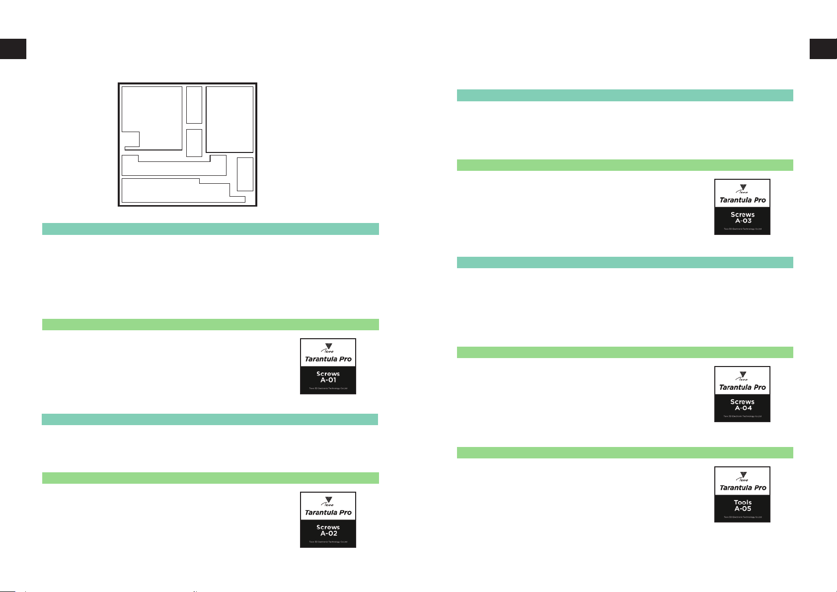
LAYER A
Screws
A-04 A-04
A-03
A-02
A-01
A-01
SKU Item Pcs Description pics
53-01326A T8 Lead scew,8mm,4 teeth,390mm 1
52-01692A Aluminum extrusion,2040,400mm,V slot,Y axis 1
52-01694A Aluminum extrusion,2040,350mm,V slot,right 1
52-01695A Aluminum extrusion,2040,350mm,V slot,left 1
52-01693A Aluminum extrusion,2040,250mm,V slot,mid 1
A-01 Screw bag
SKU Item Pcs Label
56-01687A M5x30 socket head bolt 4
56-01337A M5x45 socket head bolt 4
56-00076A M5 whasher 8
56-01271A M4x20 socket head bolt 4
56-00003A M4 T NUT 4
59-01597A Rubber foot, 24*19*31mm, 5mm diameter 4
A-02
SKU Item Pcs Description pics
53-01723A Front panel,for screen 1
11-01200A MKS MINI12864 LCD 1
A-02 Screw bag
SKU Item Pcs Label
56-00304A M3x4 Bolt 8
56-01208A M3x10 Spacer 4
56-00374A M4x6 Bolt 5
56-00003A M4 T nut 4
09-01080A LCD wire, 10pin, 0.4m 2
LCD button 1
A-02
A-03
SKU Item Pcs Description pics
07-00032A Stepper Motor,40mm 1
56-01696A Metal panel,for Y axis 1
A-03 Screw bag
SKU Item Pcs Label
56-01697A Y frame 1
53-00169A Flange bearing F624zz 2
56-01335A M4x25 socket head bolt 2
53-01338A Spacer 4.2mm*7mm 6mm high 1
56-00624A M4 locknut 2
56-00460A M4x8 socket head bolt 5
56-00003A M4 T nut 5
56-00854A M3x6 button head bolt 4
53-00008A Timing wheel 5mm 1
A-04
SKU Item Pcs Description pics
02-01780A Mainboard(pre-assembled) 1
02-01781A Power supply(pre-assembled) 1
A-04 Screw bag
SKU Item Pcs Label
56-00292A M5x8 flat head bolt, M/C 6
56-00620A M5 T NUT 4
A-05 Tools bag
SKU Item Pcs Label
59-01250A TPFE Tube, 2x4mm, 0.41M length 2
09-01083A USB wire, 0.5m 1
60-00359A Small Shovel 1
99-01617A Needle, 0.3x40mm 1
61-01440A QR card 1
57-01264A PP bag, 16x24cm 1
58-01672A Test Filament, 10M 1
61-00109B Business Card 1
05 06
Page 5
53-00008A Timing wheel 5mm 1
Packing listPacking list
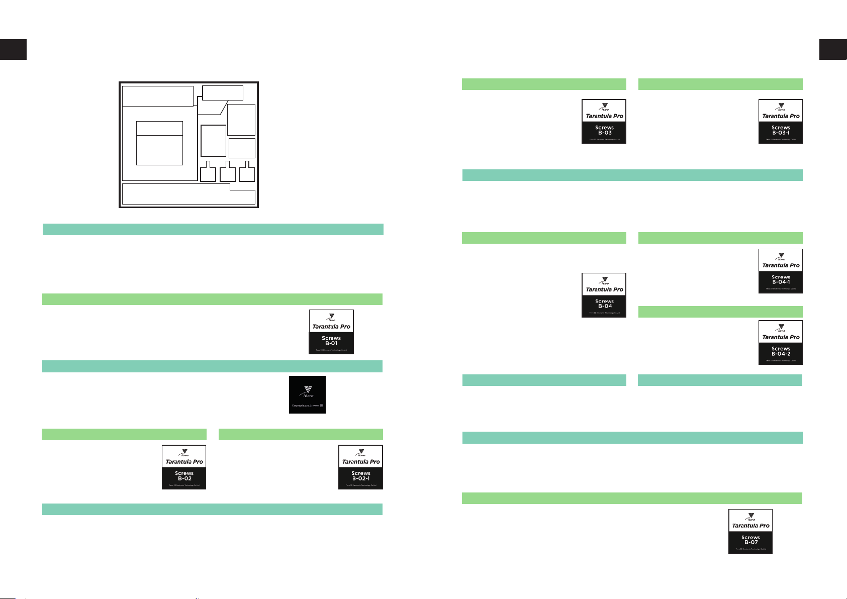
LAYER B
B-01
SKU Item Pcs Description pics
52-01315A Aluminum extrusion,2020,330mm,V slot 1
52-01316A Aluminum extrusion,2020,345mm,V slot 1
52-01691A Aluminum extrusion,2040,424mm,V slot 2
B-01 Screw bag
SKU Item Pcs Label
56-00617A M5x25 socket head bolt, M/C 9
56-00076A M5 whasher, 1mm thickness 9
B-02
SKU Item Pcs Description pics
56-01698A Sheet Metal,for bed support 1
51-01757A PC film 1
02-01782A Heating bed(pre-assembled) 1
Screws
B-02
B-01
B-05
B-03
B-04
B-06
B-07
B-03 Screw bag
SKU Item Pcs Label
56-01256A M3x10 button head bolt
56-00854A M3x6 button head bolt
56-00060A M3x12 socket head bolt, M/C
56-00066A M3 NUT
56-01064A M3 washer
56-00675A T8 Leadscew nut, 4 teeth,8mm
56-00276A M5x15 flat head, M/C
56-00076A M5 washer, 1mm thickness
56-00453A M3x30 button head bolt
53-00008A Timing wheel 5mm
B-04
SKU Item Pcs Description pics
53-01734A Sheet Metal,for left X axis 1
56-01703A Sheet Metal, for E3D 1
56-01701A Sheet Metal, connect E3D with X axis 1
B-04 Screw bag
SKU Item Pcs Label
59-00005A V-wheel 24mm
53-00671A Spacer 5x8mm, 7mm length
53-01191A Eccentric nut
56-00075A M5 Locknut
56-00277A Copper Pad 5x8x1mm
56-00586A M5x30 flat head bolt, M/C
56-00617A M5x8 flat head bolt, M/C
56-00620A M5 T NUT
53-01269A Flange bearing F604zz
56-01271A M4*20 socket head bolt,M/C
53-01338A Spacer 4.2x7mm, 6mm length
56-00274A M4 NUT
B-05
SKU Item Pcs Description pics
02-01784A
E3D (Pre-assembled)
2
2
4
4
4
1
3
2
3
1
3
2
1
3
1
3
3
3
2
2
1
1
1
B-03-1 Screwbag
SKU Item Pcs Label
56-00617A
56-00620A
B-04-1 Screw bag
SKU Item Pcs Label
59-00005A V-wheel 24mm
53-00671A Spacer 5x8mm, 7mm length
53-01191A Eccentric nut
56-00075A M5 Locknut
56-00277A Copper Pad 5x8x1mm
56-00273A M5x25 flat head bolt,M /C
56-00058A M3x8 socket head bolt,M/C
56-00855A M3x8 button head bolt
B-04-2 Screw bag
SKU Item Pcs Label
56-01706A Leadscrew fix part(printed)
53-00656A Flange bearing F688zz
56-00292A M5x8 flat head bolt, M/C
56-00620A M5 T nut
56-01213A M5x8 button head bolt
B-06
SKU Item Pcs Description pics
02-01165A
M5x8 bolt, M/C
M5 T nut
Y endstop(prebuilt)
X endstop(prebuilt)
Titan extruder(pre-assembled)
3
3
2
1
1
3
2
1
3
1
3
2
4
1
1
2
2
1
B-02 Screw bag
SKU Item Pcs Label
59-00005A Wheel 24mm 4
53-00671A Aluminum column 5x8mm, 7MM length 2
53-01191A Eccentric wheel 2
56-00075A M5 locknut 4
56-00277A Copper Pad 5x8x1 2
56-00586A M5x30 flat head, M/C 4
B-03
SKU Item Pcs Description pics
02-01783 X carriage, left(pre-assembled) 1
B-02-1 Screwbag
SKU Item Pcs Label
56-01700A M4x40 bolt, M/C 4
56-01699A Springs 4x8mm, 25mm length 4
56-01601A M5, Knurled thumb nuts 4
B-07
SKU Item Pcs Description pics
07-00032A Stepper motor,40mm 3
B-07 Screw bag
SKU Item Pcs Label
53-00009A Coupler,5mm 8mm 1
53-01303A CNC 1
56-00003A M4 T-nut 3
56-00302A M4x12 Socket head bolt 3
56-00950A M3x14 bolt 3
59-01076A 0 Ring 1
07 08
Page 6
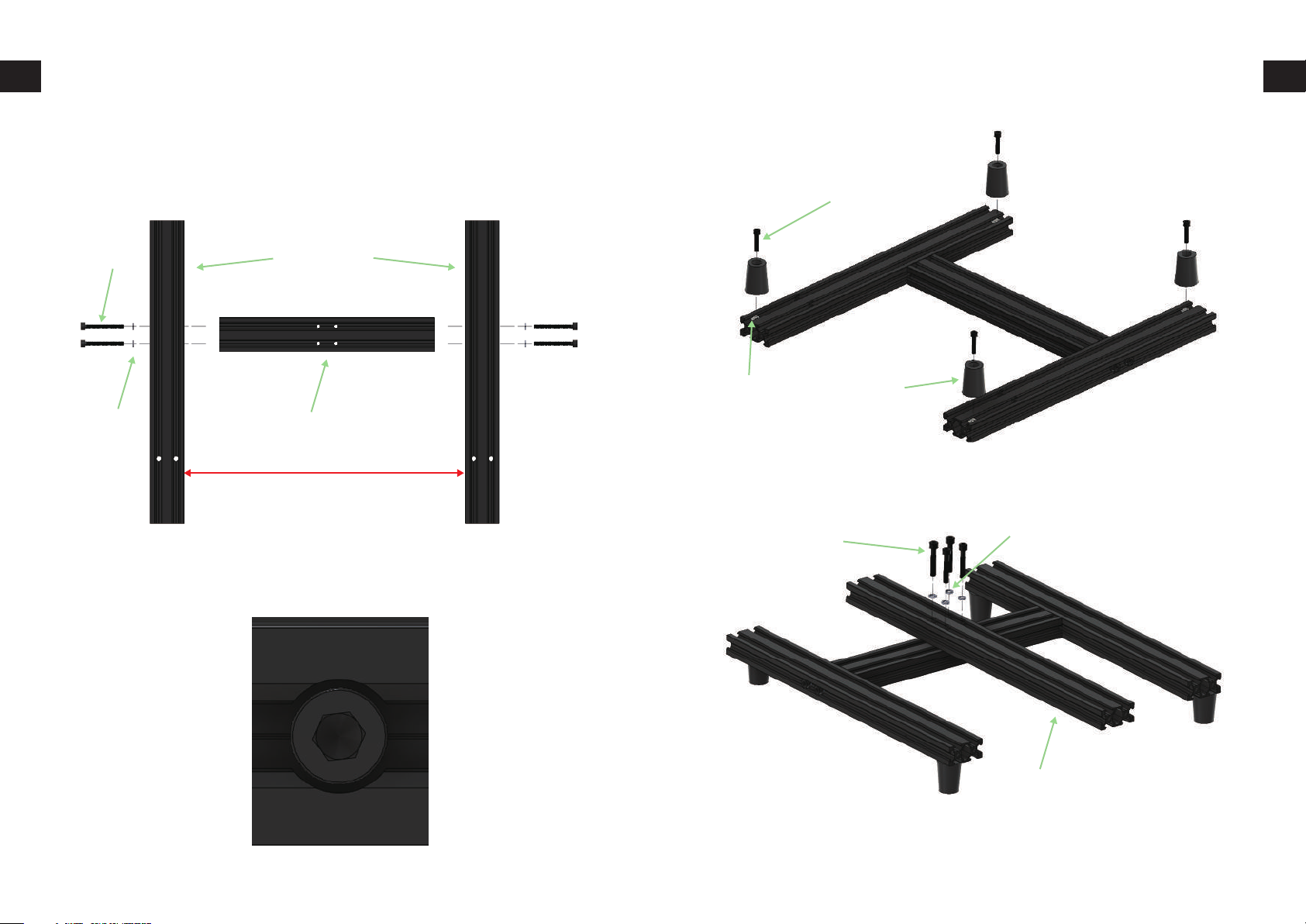
Assembly of the bottom frame A-01 Assembly of the bottom frame A-01
Line up the extrusions as in picture and fasten those together using
M4x45 bolts and M5 spring washers. The parts needed for this
assembly are found from A-01 bag and A-01 slot.
4 x M4x20 bolt
4 x M5x45 bolt
4 x M5 spring washer
2x20x40 350mm
20x40250mm extrusion
_+
250mm
Give special attention for right orientation of the profiles and the
round slots. Those round slots are meant to countersunk bolts so
that bolt head will be hidden.
4 x T-nut
4 x rubber foot
4 x M5 spring washer
4 x M5x30 bolt
20x40250mm extrusion
09 10
Page 7
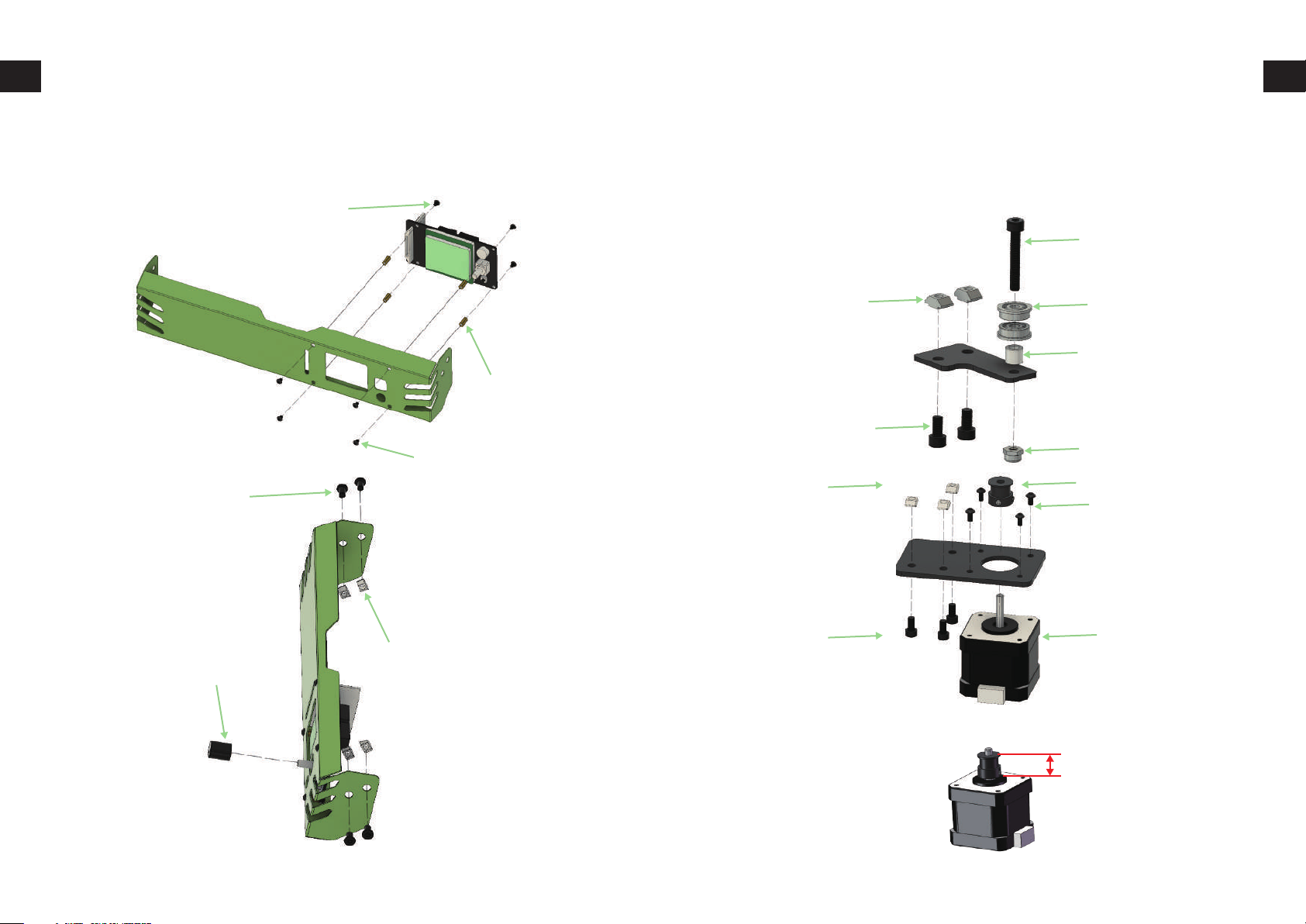
Front panel assembly A-02
Y axis parts preparation A-03
Prepare the front panel as shown and then slide it in frame, you can
find these items from slot A-02 and A-02 bag.
4 x M3x4 bolt
4 x M3 spacer
4 x M3x4 bolt
4 x M4x6 bolt
Prepare the Y axis idler and motor plate as shown in the following
pictures. Leave the M5 bolts with T-nuts loose until the parts will be
installed to the frame. The parts for these steps are found from slot
A-03 and bag A-03
M4x25
2 x T-nut
2 x M4x8
3 x T-nut
2 x F624zz bearing
Aluminum spacer
M4 Self-locking nut
GT2 pulley
4 x M3x6 Button head screw
Nema 17 motor
1 x knob
4 x T-nut
3 x M4x8 bolt
The y motor’s timing wheel distance around 20mm.
20-20.1mm
11 12
Page 8
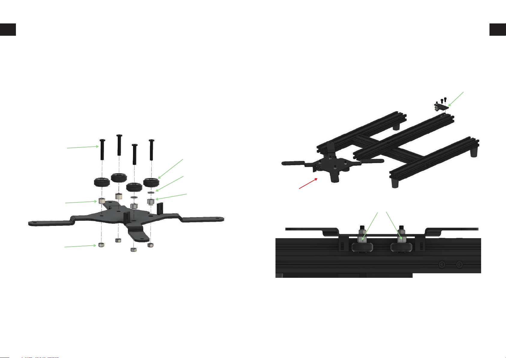
Bed carriage assembly B-02
Finalizing the assembly A-01, A-02, A-03 and B-02
Assemble the bed carriage as in picture. Tighten the two bolts which
have 6mm spacers gently but leave the two eccentric nut bolts
slightly loose so that eccentric nuts turn easily. The parts for this step
are found from B-02 slot and B-02 bag.
4 x M5x30 bolt
4 x V-wheelst
2 x M5 precision
2 x eccentric
2 x 7mm spacer
Slide the bed in extrusion and install idler plate in the end of extrusion
as shown. Then slide carriage in frame and use the key to adjust the
eccentric nuts so that carriage is snug fit to rails and carriage moves
smoothly. In the end tighten the M5 nuts gently.
Idler
Eccentric nuts for carriage
4 x M5 locknuts
Install the X axis motor bracket and endstop in place and tighten the
bolts.
13 14
Page 9
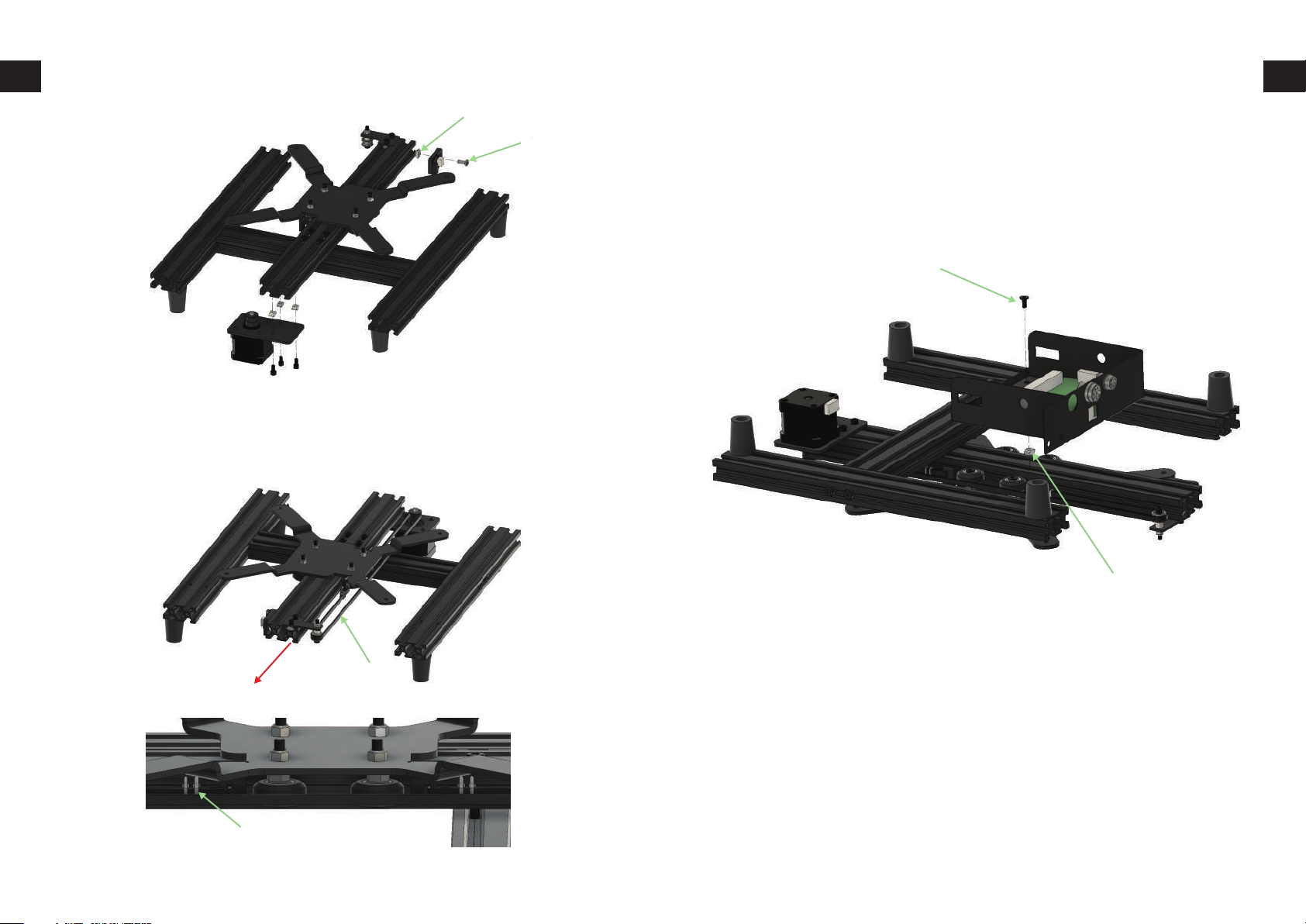
Finalizing the assembly A-01, A-02, A-03, B-02, B-03
M5 T-nut
M5x8 bolt
Loop the GT2 belt around idler and motor pulley and connect both
ends to slots in heatbed carriage with zipties. Last step is to tighten
the belt which can be done by loosening slightly two M5 bolts holding idler plate in extrusion and sliding idler plate so that belt tightens
and then tightening the bolts again.
Controller, PSU and front panel installation
Install the controller and PSU in the frame. Items required are found
from slot A-04 and bag A-04. Use the M5x8 bolt and T-nut to attach
controller to middle extrusion as shown.
M5x8 lowprofile bolt
T-nut
GT2 belt
Install the M5x8 bolts and T-nuts as shown. Slide the PSU in extrusion
as far as it goes and tighten the bolts.
Ziptie
15 16
Page 10
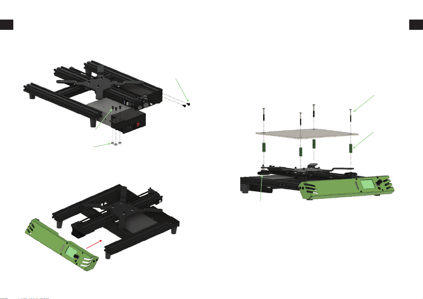
Controller, PSU and front panel installation
2 x M5x8 lowprofile
Hotbed assembly
Install the hotbed and tighten the nuts just some turns as these are
later used to adjust the bed level. These parts can be found from bag
B-02-1.
4 x M4x40 countersunk
3 x M5x8 lowprofile
3 x T-nut
Slide the front panel in extrusions and tighten the M5 bolts in both
sides of the front panel.
*
4 x bed spring
4 x thumb nut
17 18
Page 11
X axis assembly left side B-03
X axis assembly left side B-03
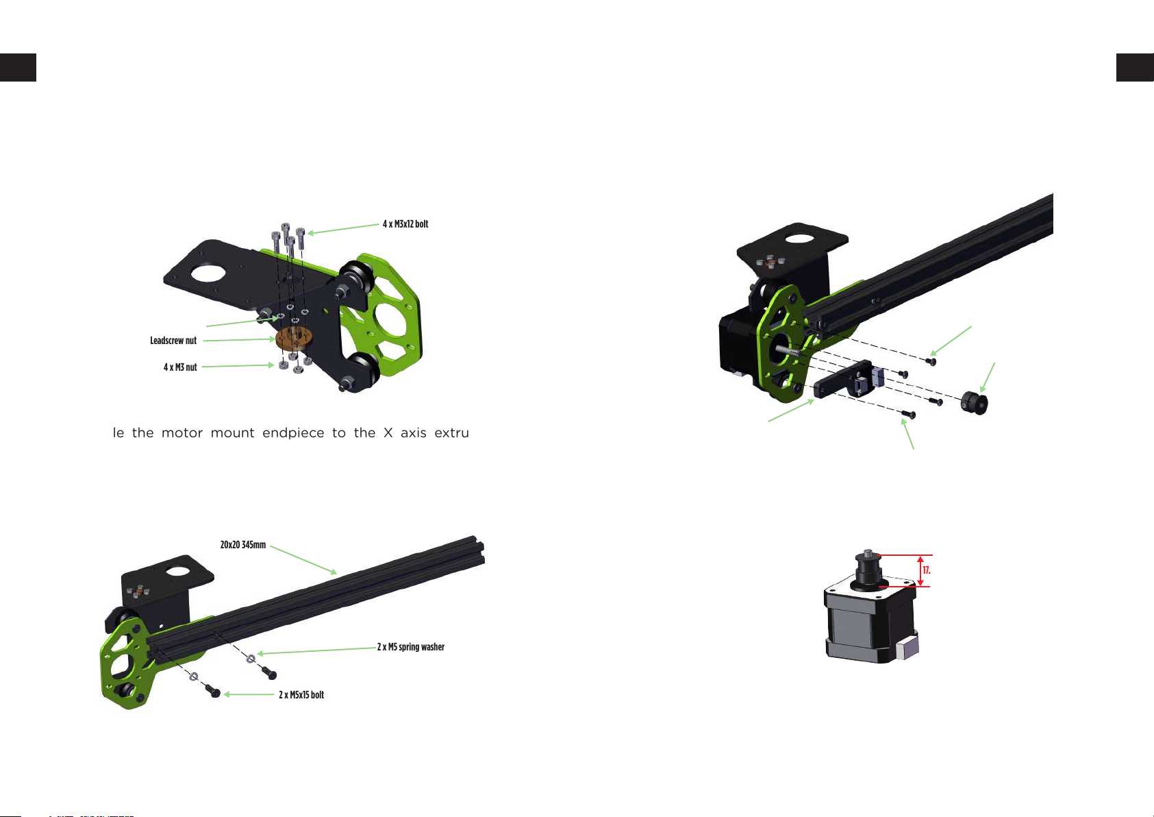
Install the leadscrew nut as shown.From B-03. Then install the stepper motor pulley and limit switch to the endpiece.
Motor cable connector should face downwards. From slot B03 and
B03-1 bag.
4 x M3x12 bolt
4 x M3 spring washer
Leadscrew nut
4 x M3 nut
Assemble the motor mount endpiece to the X axis extrusion as
shown. There is two bolt slots that match to the motor mount endpiece threaded holes. The parts for these steps are found from slot
B-03.
20x20345mm
2 x M5 spring washer
2 x M5x15 bolt
2 x M3x6 button head
GT2 pulley
X endstop (B03-1)
2 x M3x10 button head
The x motor’s timing wheel distance around 17.5mm.
17.5 -17.7 mm
19 20
Page 12
Right side and hotend assembly B-04
Right side and hotend assembly B-04
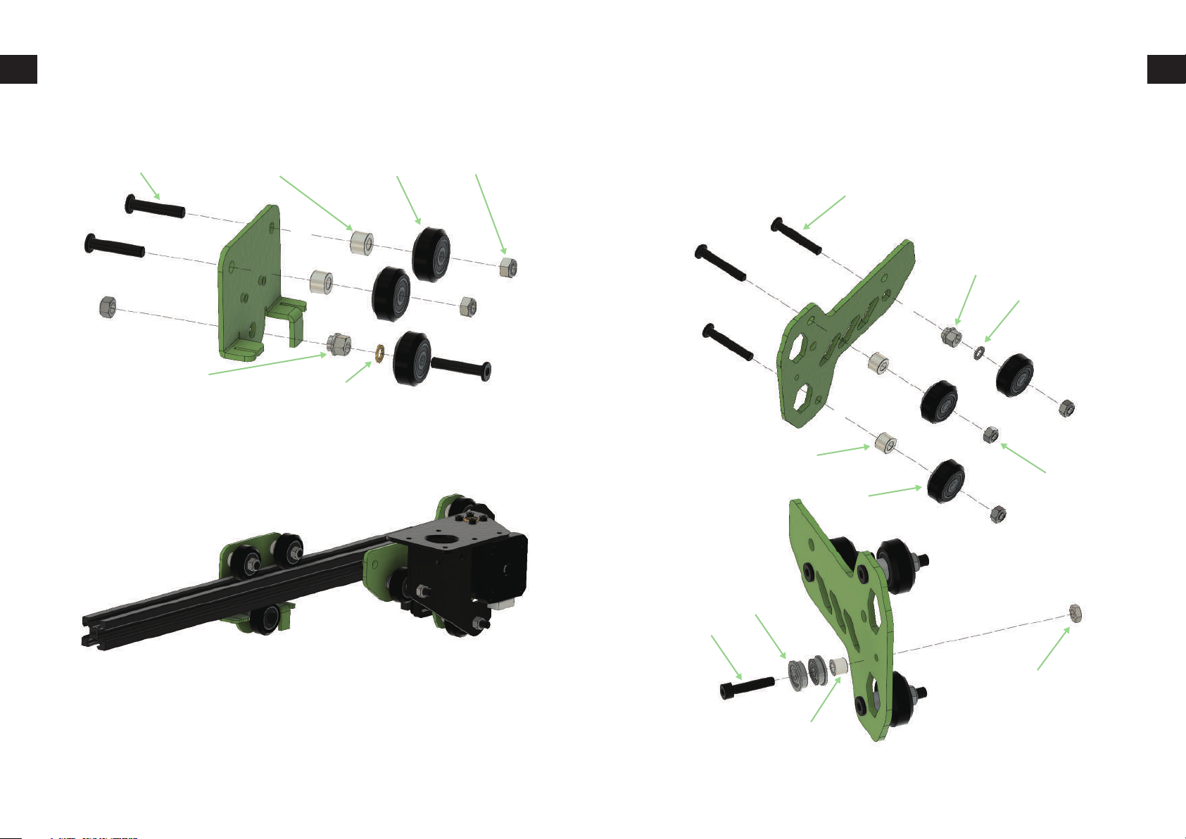
Assemble the hotend carriage as shown. Parts for this step are found
from slot B-04 and bag B-04-1.
3 x M5x25 low profile 2 x M5 7mm spacer 3 x V-wheels 3 x M5 locknut
Eccentric nut
Washer
Install hotend carriage to extrusion and tighten the eccentric nut
again as explained in the heat bed assembly.
3 x M5x30 low profile boltAssemble the second endplate to the X axis
as shown. The parts for this step are found from bag B-04 and slot
B-04
3 x M5x30 low profile
Eccentric nut
M5 precision shim
2 x M5 7mm spacer
3 x M5 locknut
3 X V-wheel
2 x F604ZZ
M4x20 bolt
M4 nut
4.2x7x6 spacer
21 22
Page 13
Right side and hotend assembly B-04
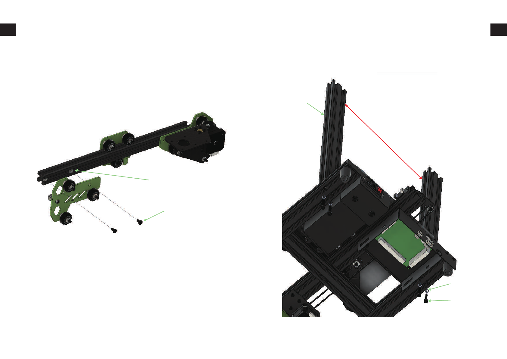
Upper frame assembly
Install the assembly to other side of extrusion as shown, you can
leave the M5x8 bolts slightly loose still as those will be tightened
later in assembly. Don't tighten the screws in case you need to adjust
the granty later.
2 x T-nut
2 x M5x8 low profile
Install the two Z axis extrusions to bottom frame using 4xM5x25 bolts
and 4xM5 spring washers. The parts are found from slot B-01 and bag
B-01.
2 x 20x40 424mm
250mm
4 x M5 spring
4 x M5x25 bolt
23 24
Page 14
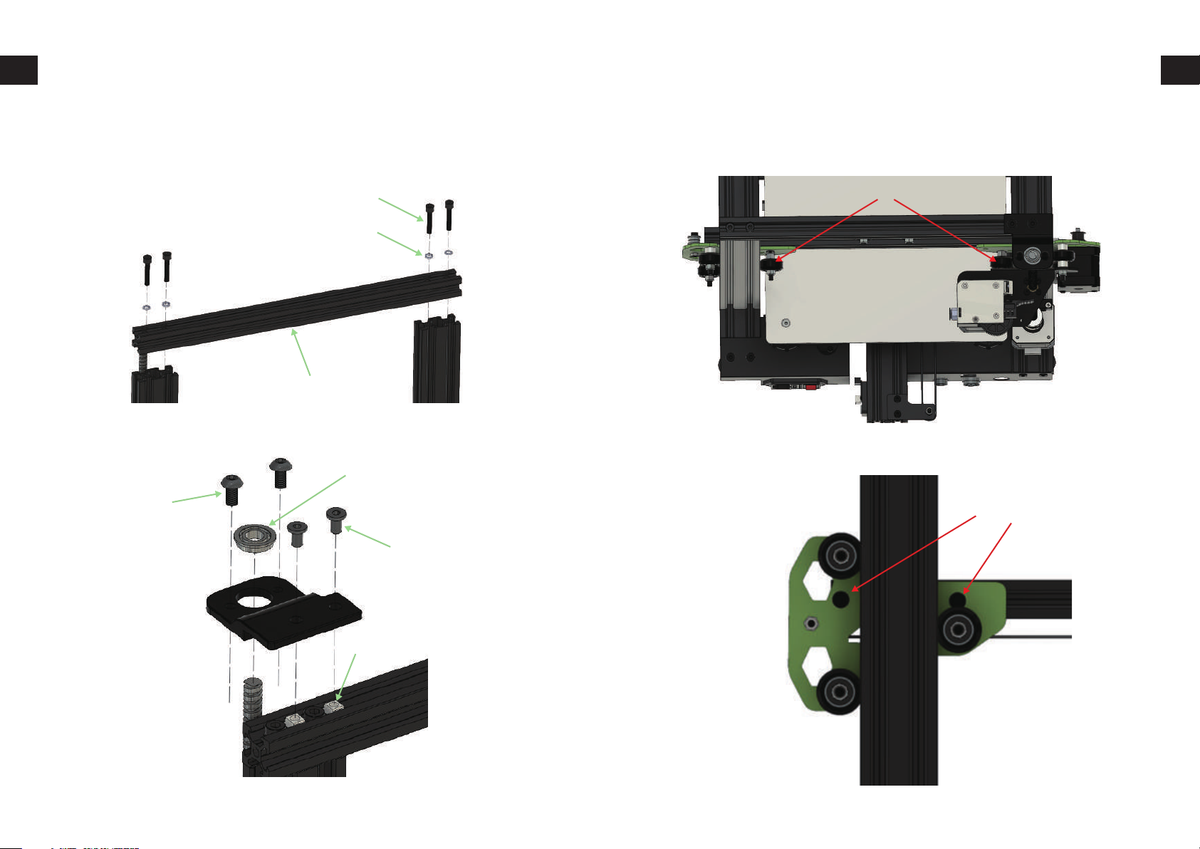
Z axis assembly B07
Z axis assembly B07
4 x M5x25 boltInstall the leadscrew top bearing bracket and Z axis
top extrusion as shown in the following pictures. The parts for leadscrew bracket can be found from bag B01
4 x M5x25 bolt
4 x M5 washer
2020 330mm extrusion
Scews from B04-2.
F688zz bearing
2 x M5x8 button head
After this adjust again eccentric nuts so that Z axis moves smoothly
and then tighten again the M5 nuts. And as last step for X axis tighten
the two M8x5 bolts on right side.
Pull the carriage out make sure it fix well.
Tighten now these
2 x M5x8 low profile
2 x T-nut
25 26
Page 15
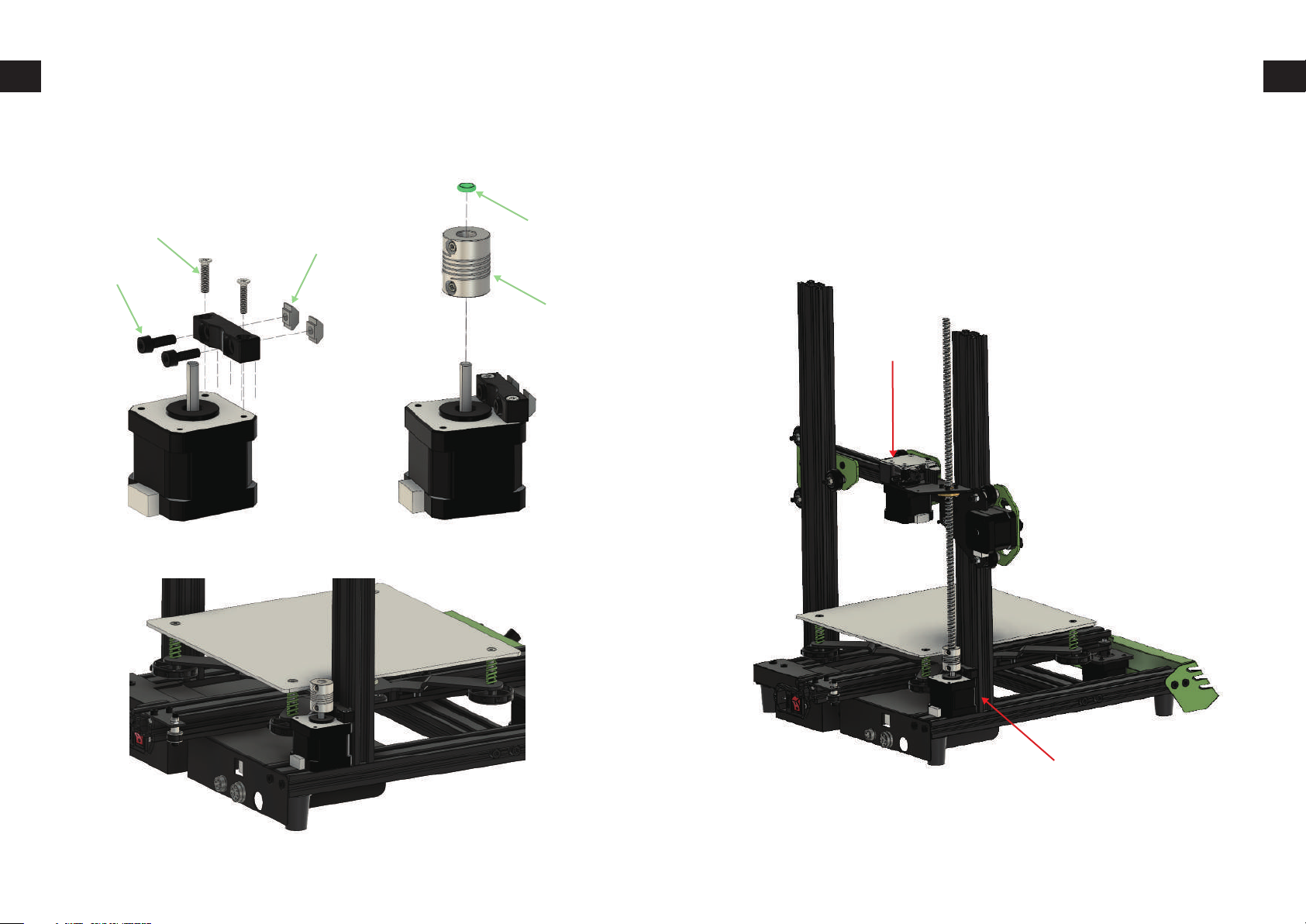
Z axis assembly B07
Z axis assembly B07
Install the motor bracket and coupler with O-ring as shown and
install then it to the Z axis extrusion as shown. The parts are found
from slot B-07 and bag B-07.
2 x M3x14 countersunk
2 x T-nut
2 x M4x12 bolt
O-ring
Coupler
You can now turn the leadscrew around midway in the leadscrew nut
and slide the X assembly on frame. Slide it down until the leadscrew
goes inside the coupler and then tighten the coupler holding screw.
27 28
Page 16
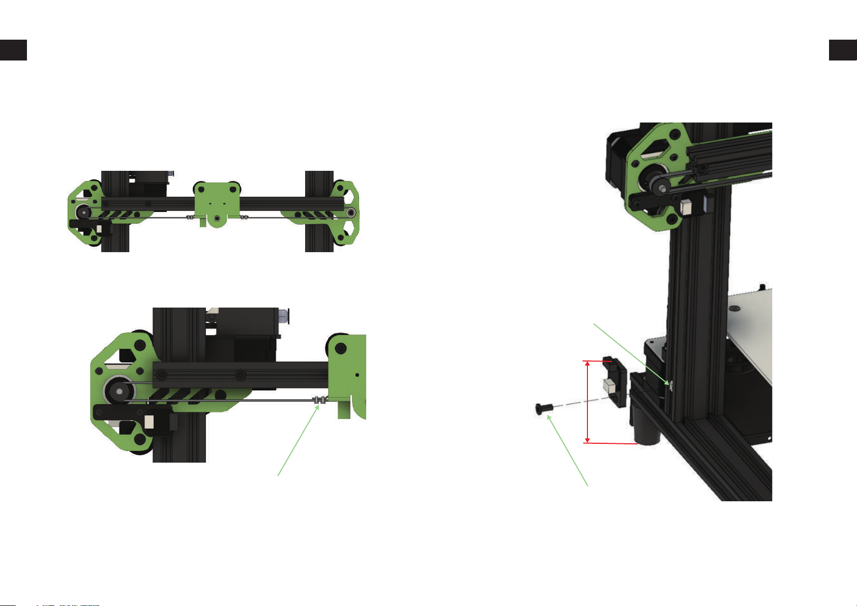
Z axis assembly B07
Z axis assembly B07
Loosen the X axis stepper bolts slightly so that stepper can move in
the slots. Install tightly the X axis belt and use zip ties to attach it to
carriage and then you can use stepper to tighten the belt little more
and then tighten the screws.
Install the Z axis endstop as shown.
T-nut
100mm
Zipties
M5x8 low profile
29 30
Page 17
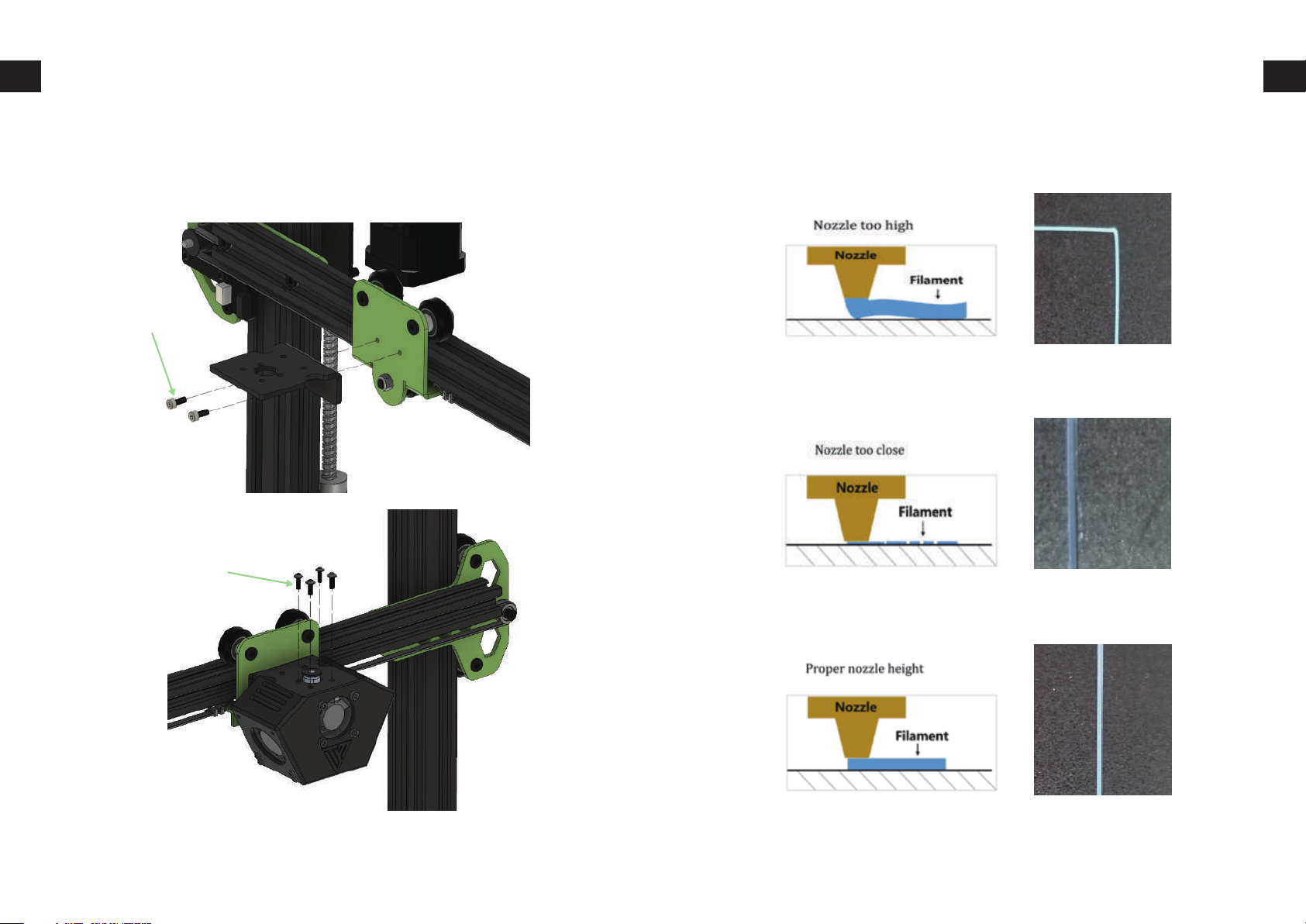
Hotend assembly B-04
Bed leveling
Install the hotend holding plate and hotend assembly as shown in
pictures. Parts can be found from bag B-04-1 and slot B-04.
2 x M3x8 bolt
4 x M3x8 button head
Adjust the wheels locate in 4 corners and make the filament come out
good as shown in picture “Proper nozzle height”.
31 32
Page 18
Prepare Slicing Software
This printer works with most slicing / printing software like Repetier-Host, Cura, Simplify3D, etc. But we will go in details for Repetier-Host and tell you how to set it up so that you can make your first
print. First, you can download the software from our website at
http://www.tevo.cn/software-download.php
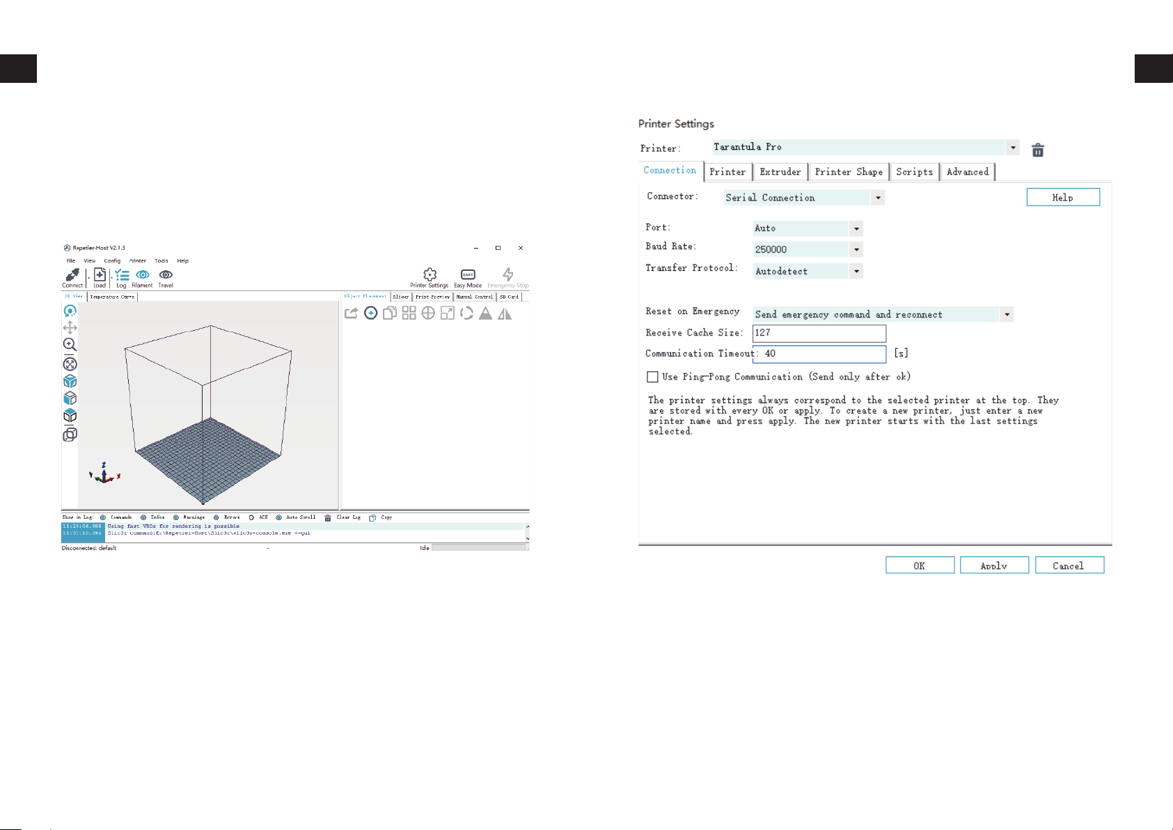
After installation in done and you start the software, you should get
the following screen:
Prepare Slicing Software
Now we have to set up our printer in the settings so that Repetier-Host can connect to it and will know what size of the build area
our printer use. Open the Printer Settings window (click Config
Printer Settings).
First set port to whatever port your printer use (you have to connect
the printer to your computer before this step, or you can skip Port
setting if you are going to print SD card only.) Set Baud Rate to
250000 and DO NOT touch any other settings in this tab.
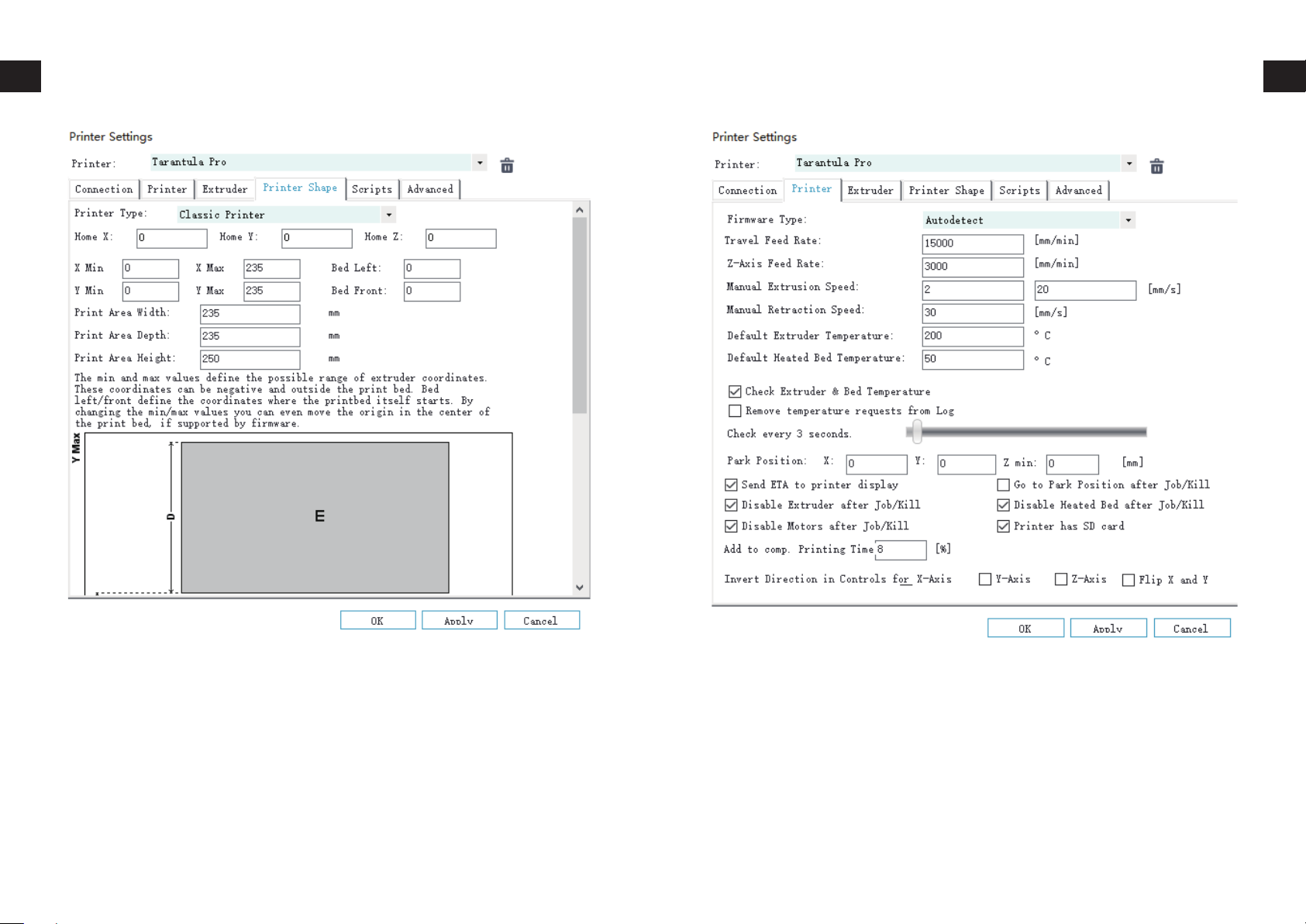
Click on Printer Shape tab, change the following values:
X Max – 240
Y Max – 240
Print Area Width – 235
Print Area Depth – 235
Print Area Height – 250
33 34
Page 19
Prepare Slicing Software
Prepare Slicing Software
Go to Printer tab, change the following values:
Travel Feed Rate – 15000
Z-Axis Feed Rate – 15000
Manual Extrusion Speed – 2 / 20
Manual Retraction Speed – 30
Default Extruder Temperature – 200
Default Heated Bed Temperature – 55
Then click on OK to save the settings.
35 36
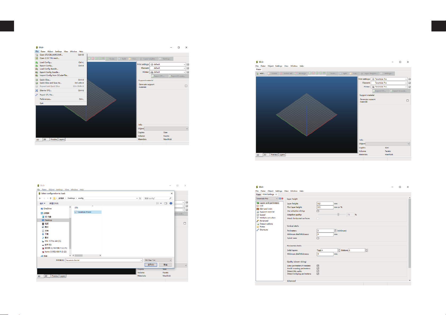
On Repetier-Host main screen, click on Slicer tab on the right. Choose
Slic3r from Slicer drop-down then click on Configuration button.
On Slic3r window, click on File -> Load
Page 20
Prepare Slicing Software
Browse to the SD card or the location you saved the config file. (You
can download the latest version of the config file from http://www.tevo.cn/software-download.php) Select the ini file and click on
Open.
Prepare Slicing Software
Click on the Gear icon next to Print settings, Filament, Printer respectively.
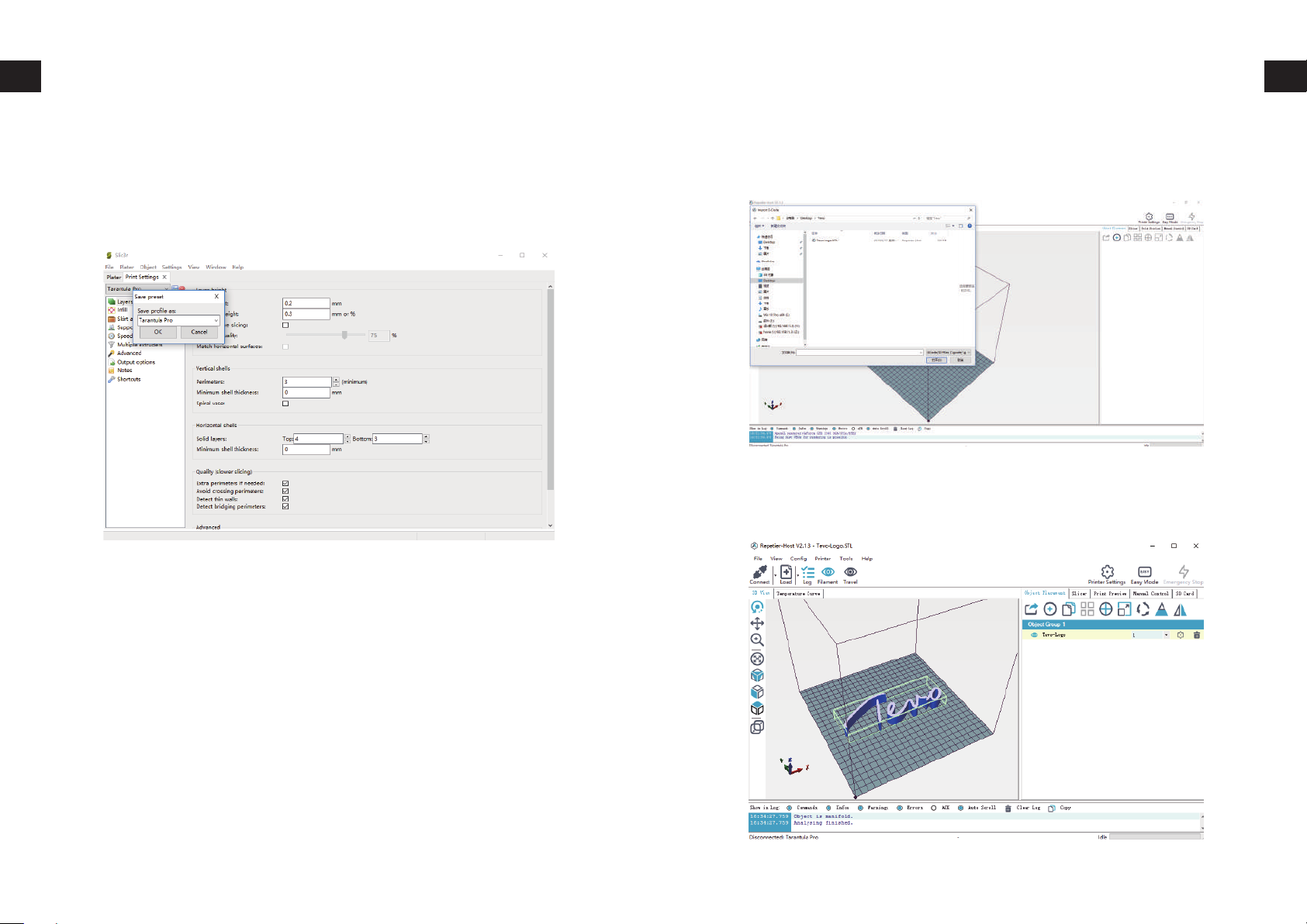
Click on the Save icon on the next page, rename it to tevo-Tarantula
pro or any name of your choice.
37 38
Page 21
Prepare Slicing Software
How to Slice 3D Object for SD Print
Click on Plater tab to go back to the main screen and do the same
for others.
Click on Load, browse to location of the file to print, then choose
Open. (Or you can drop and drop the STL file to Repetier-Host software.)
Click on Slicer tab on the right.
39 40
Page 22
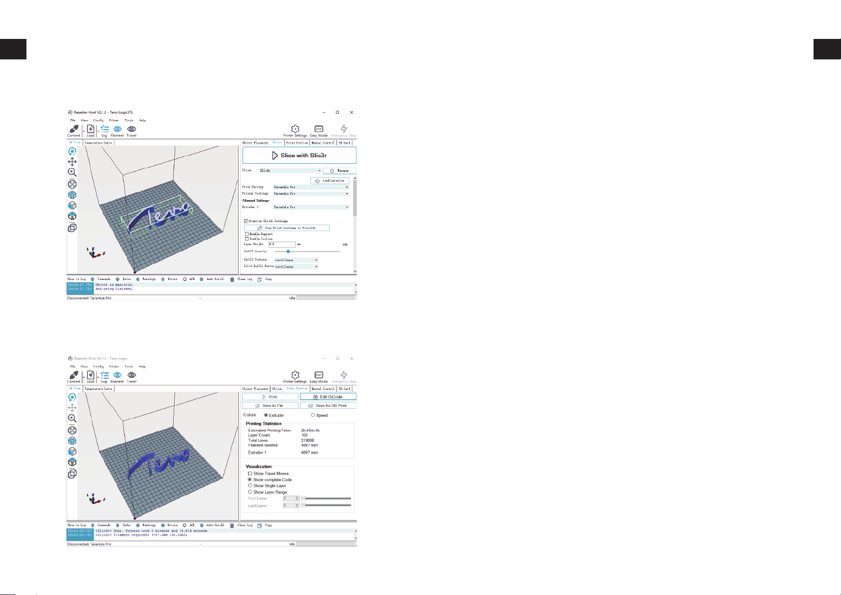
How to Slice 3D Object for SD Print
How to Flash Firmware
Choose the config saved in previous step. Then click on Slice with
Slic3r.
After slicing, click on Save for SD Print to save the G-code file to the
SD card with file name of your choice. Then you can insert the card
to your printer and choose Print from SD to start printing.
To install firmware on your printer, you’ll need to download the following:
Arduino IDE (http://www.arduino.cc)
1.
Firmware Source Code (You can get it from many sources, e.g.
2.
our Facebook Page Files section, our Customer Service, Software Download page on http://www.tevo.cn, or from Marlin
directly.)
In this chapter, we’re going to use Marlin for demonstration.
Configuration downloaded from our Facebook page, customer
service, or software download page are pre-configured, you can use
it without any modification. We’re not going to go into details how to
configure from scratch.
To start the process, do the following steps:
Connect your printer to your computer with USB cable supplied.
1.
Double-click Flash.ino (or Marlin.ino) file to open it in Arduino
2.
IDE.
3.
Select Arduino/Genuino Mega or Mega 2560 from Tools ->
Boards menu.
Select the serial (USB) port that your board is connected to in
4.
Tools -> Serial Port menu.
5.
Click on Verify/Compile button at the top of the window to
make sure there are no configuration errors. (If failed to compile,
please make sure you are using Arduino IDE 1.8.5 or up.)
6.
After it compile successfully, click on Upload button.
Waiting for Arduino IDE to show Done uploading.
7.
41 42
Page 23
Troubleshooting
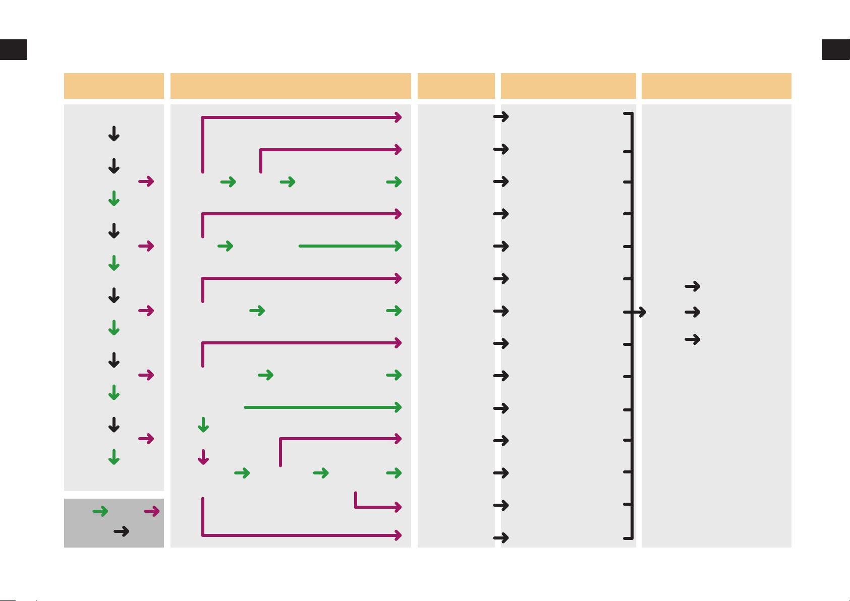
Work Process Troubleshooting Cause Treatment Feedback
Troubleshooting
Start SD Card
Print from SD
Y/N
Auto home
Y/N
Heating bed
Y/N
Nozzle heating
Y/N
File read
Moving
Bed is heated
Nozzle is heated
Garbled Other file print ok
Out of limit
Temperature is read
Temperature is read
File name
Slicing
axis motor
End stops
Heat bed
Thermistor
Heating tube
Thermistor
1. Clean the SD Card
2. Format SD Card
3. Change SD Card
Change file name
into English/numbers
Move the model
and slicing again
Relink the wires
Relink the wires
Relink the wires
Relink the wires
Relink the wires
Relink the wires
Result
Troubleshooting
Component
damaged
Unknow reason
Filament Feeding
Y/N
Done
YES
Process
NO
Wrong result
Filament out
E stepper
is working
Extruder
is working
Filament
is ok
Slicing/Belt
Couper
Other
Filament
E stepper
Slicing the file again
Print from SD
1.Clean the filament
2.Change a filament
Relink the wires
43 44
Page 24

Tevo After-Sales Tevo After-Sales
SERVICE INFORMATION
1. REPLACEMENT PARTS
Tevo products are covered under a Replacement Part Program
1.1.
for a period of 12 months from the date of delivery.
1.2.
Missing/Damaged/Defective Parts.
1.2.1.
1.2.2.
1.3.
1.3.1.
2. CARRIER LOSS, MISSING, DAMAGED, AND DEFECTIVE PARTS
2.1.
2.1.1.
2.1.2.
2.1.3.
Within 7 days of the delivery date, Tevo will replace any
parts free of charge including shipping fees.
After 7 days of the delivery date, Tevo will replace any
parts free of charge BUT the customer will be responsible
for shipping fees.
Customer Damaged Parts.
The customer shall pay for the cost of the parts AND the
shipping fees.
Claims for lost or damaged shipments must be reported to the
carrier within the carrier’s claim window, the customer needs
to inform Tevo within 7 days of the delivery date.
For any parts lost or damaged during shipping, the
customer shall take photos or video and submit them
when filling out a Service Ticket. If a claim number was
issued by the carrier, please include the claim number
when creating your Service Ticket (Report a Problem /
Carrier Lost Parts.)
Once the Carrier dispute is resolved, please provide Tevo
with all communications with the carrier. It is the customer’s responsibility to keep Tevo up-to-date with ALL communications with the carrier.
Tevo will work with the customer on replacing the parts in
the claim.
2.2.
2.3.
2.4.
2.5.
2. GENERAL SUPPORT
For Missing Parts, refer to section 1.2, the customer shall fill out
a Service Ticket (Report a Problem / Missing Parts.)
For Damaged Hardware Parts, refer to section 1.2, the customer shall take photos or video and submit them when filling out
a Service Ticket (Report a Problem / Damaged Hardware
Parts.)
For Defective Electronic Parts, refer to section 1.2, the customer shall take photos or video and submit them when filling out
a Service Ticket (Report a Problem / Defective Electronic
Parts.)
2.4.1.
For information and support on building and operating your
TEVO Tarantula pro 3D printer, please visit :
TEVO Tarantula PRO & Normal Prusa i3 Owners
https://www.facebook.com/groups/TEVO.3dprinter.owners/
If the part is the LCD panel, Power Supply, or Mainboard,
the customer shall ship the part back to Tevo and Tevo will
send a new part.
For parts damaged by the customer, refer to section 1.3, the
customer shall submit a Service Ticket (Report a Problem /
Customer Damaged Parts.)
45 46
 Loading...