

Page 1
Page 2

Page 3

1
READ ME FIRST!
READ THIS MANUAL COMPLETELY BEFORE ASSEMBLING AND POWERING UP YOUR
PRINTER!
Hazards and Warnings
The TEVO Black Widow 3D printer has motorized and heated parts. When the printer is in
operation always be aware of possible hazards.
Electric Shock Hazard
Never open the electronics bay of the printer while the printer is powered on. Before
removing the access door, always power down the printer and unplug the AC line cord.
Burn Hazard
Never touch the extruder nozzle, heater block, or the heated bed without first turning off
the hot end (or heated bed) and allowing it to completely cool down. The hot end (or
heated bed) can take up to twenty minutes to completely cool down. Also, never touch
recently extruded fliament. The filament can stick to your skin and cause burns.
Fire Hazard
Never place flammable materials or liquids on or near the printer when powered on or in
operation. Liquid acetone and vapors are extremely flammable.
Pinch Hazard
When the printer is in operation, be careful never to put your fingers in the movings parts,
including the belts, pulley, gears, wheels or leadscrew.
Static Charge
Make sure to ground yourself before touching the printer, especially the electronics.
Electrostatic charges can damage electronic components. To ground yourself, touch a
grounded source.
Age Warning
For users under the age of 18, adult supervision is recommended. Beware of choking
hazards around children.
Page 4

2
1. Table of Contents
1. Table of Contents............................................................................................................. 2
2. Letter from Tevo .............................................................................................................. 3
3. Lower Frame Assembly .................................................................................................... 4
4. Y Endplate and Idler Assembly ......................................................................................... 5
5. Y Motor and Idler Assembly B-13, B-18............................................................................ 7
6. Bed Carriage Assembly .................................................................................................. 10
7. Second Y Endplate Assembly ......................................................................................... 12
8. X Axis Assembly B-3, B-4 ................................................................................................ 13
9. Z Axis Uprights ............................................................................................................... 16
10. Z Axis Assembly .......................................................................................................... 18
11. Z Motor Bracket Assembly .......................................................................................... 23
12. Extruder Plate Assembly and Installation .................................................................... 25
13. Extruder Assembly and Installation ............................................................................ 29
14. X Motor and Belt Installation ...................................................................................... 32
15. Limit Switch Installation .............................................................................................. 37
16. Control Box Assembly ................................................................................................. 40
17. Mainboard Connections ............................................................................................. 42
18. Wiring Schematic ........................................................................................................ 43
19. Setting Up Repetier-Host for Printing ......................................................................... 44
20. BLTouch Calibration (only if you have BLTouch option) .............................................. 48
21. Slicer Settings for Repetier-Host ................................................................................. 49
22. First Test Print ............................................................................................................ 51
Page 5

3
2. Letter from Tevo
Dear User,
Thank you for purchasing the Black Widow 3D printer.
This guide will step you through the assembly and the first runs of the printer. If you have
any problems during assembly, please go to our Facebook group:
https://www.facebook.com/groups/TEVO.Black.Widow.owners/
If you cannot resolve your problem there, do not hesitate to contact us through the website
http://support.tevoprinter.com
The manual begins by showing all needed parts for the frame assembly. Please check if
those parts are all in your package and check if all rods are straight. You can do this by
placing them on a flat table and see if they roll. While checking the parts please do not mix
the parts of the Bags A-1 to A-8. Keep them separated to prevent using the wrong parts
during assembly.
After the parts check, to complete each step use the parts listed for that step.
Please make sure that the frame is completely square and tight in every angle by using a
geometrical triangle or any other more sophisticated square tool (not supplied with the
printer).
Page 6
4
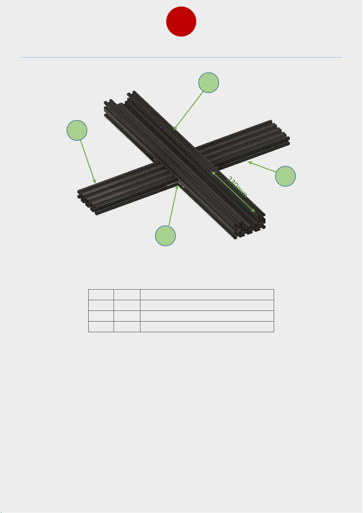
3. Lower Frame Assembly
Item
Qty
Part name
1 1 C beam extrusion L=550
2 2 2080 extrusion L=210
3 4 L corner connector
Start the assembly of the bottom of the frame by following the figure above to see how to
set the extrusions.
1
2
3
2
Page 7
5
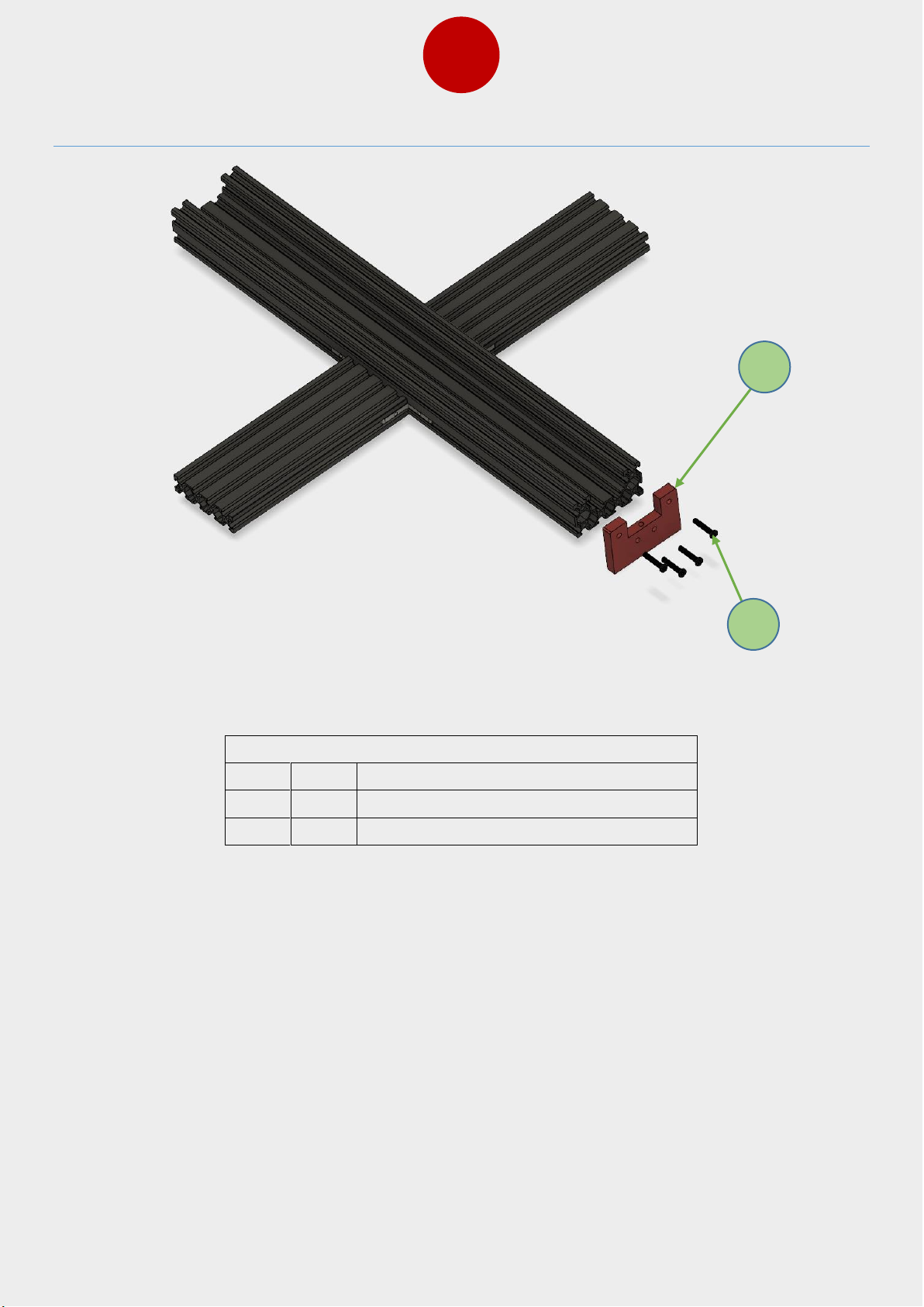
4. Y Endplate and Idler Assembly
Bag Name: B-1
Item
Qty
Part name
1 1 Y axis endplate 1
2 4 M5x20 bolts
Install the Y axis endplate 1 in place by using M5x20 bolts.
1
2
Page 8
6
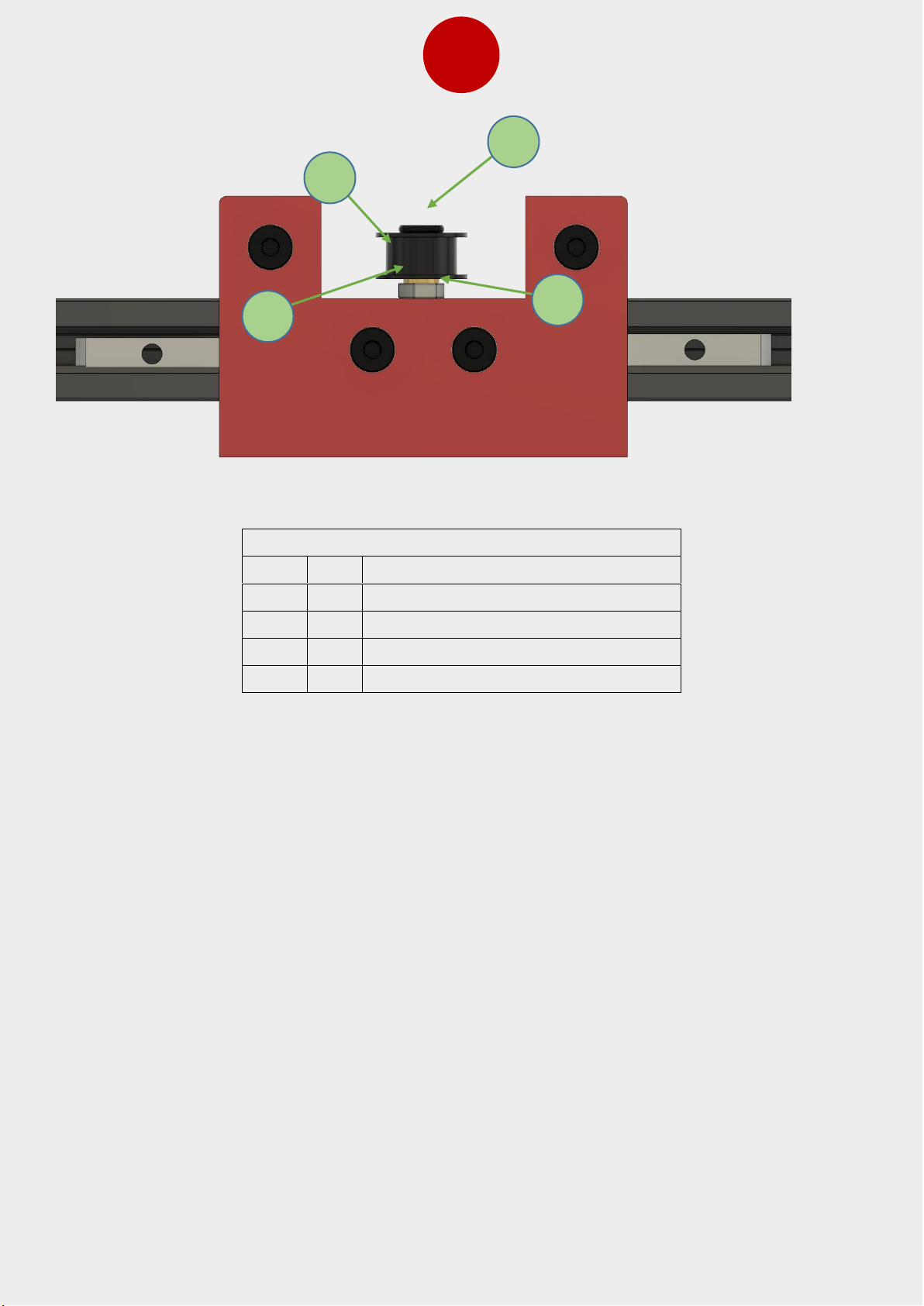
Bag Name: B-1
Item
Qty
Part name
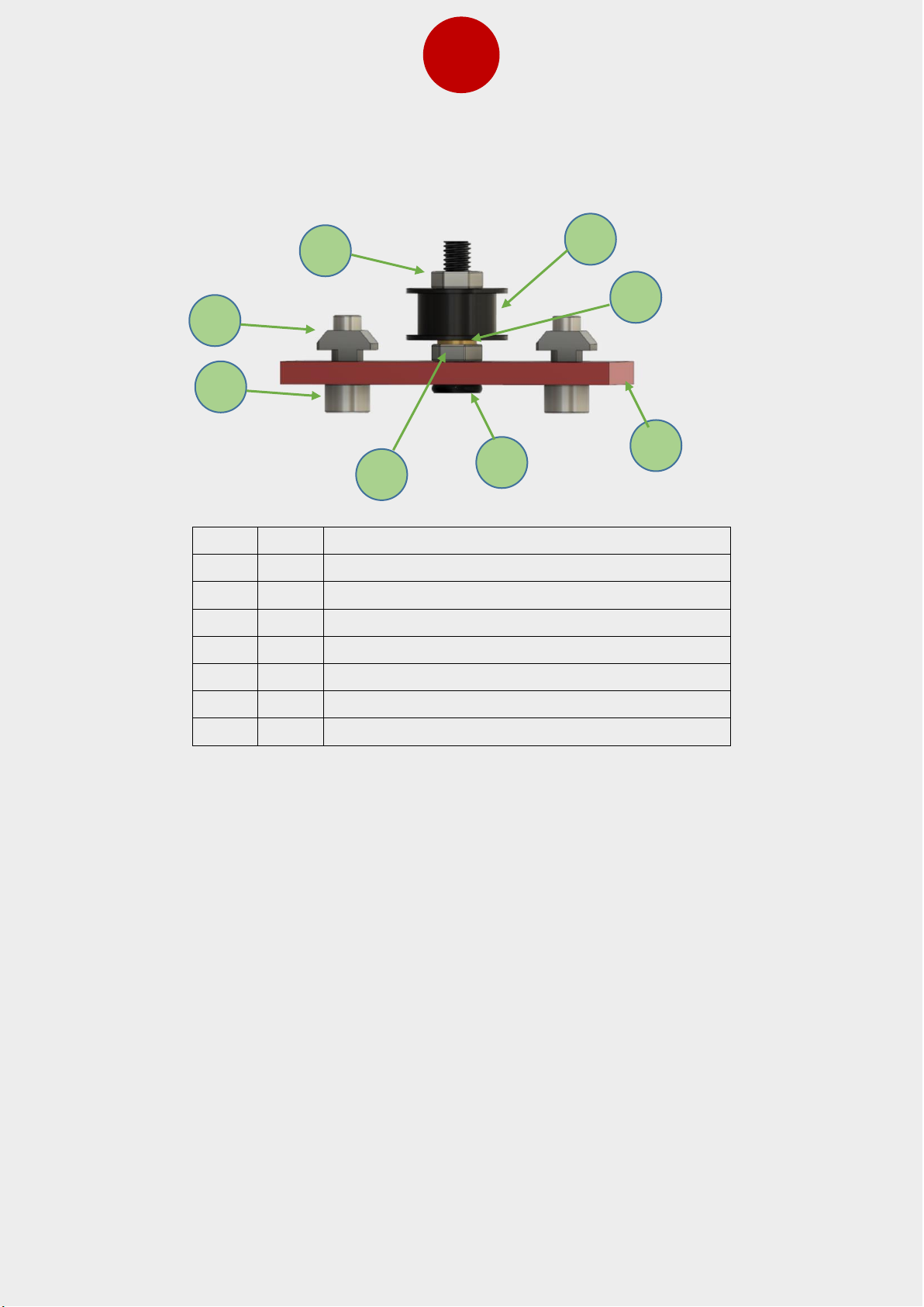
1 1 M5x25 bolt
2 1 Idler
3 1 8x5x1mm shim
4 1 M5 nut
Install the idler wheel on the Y axis front endplate as shown in the figure above. Tighten the
nut against the plate so that bolt will stay rigidly in place. The idler should be able to freely
rotate with no drag.
1 2 4
3
Page 9
7
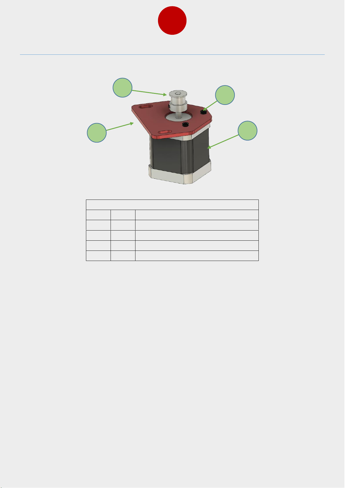
5. Y Motor and Idler Assembly B-13, B-18
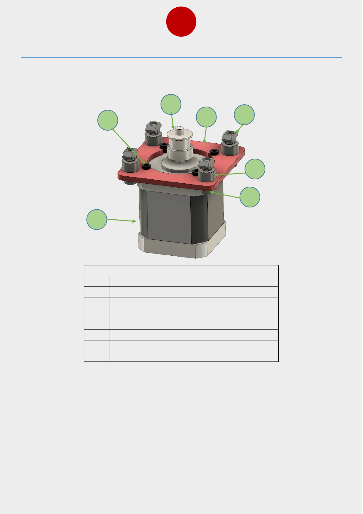
Install the motor on the Y motor upper bracket using the M3x8 bolts. Install the GT 2 gear
pulley on to the motor shaft. Make sure that you tighten 1 set screw on the flat side of the
motor shaft to prevent the gear from slipping.
Bag Name: B-13, B-18
Item
Qty
Part name
1 1 GT2 pulley
2 1 Stepper motor
3 3 M3x8 bolt
4 1 Y motor upper bracket
3
1 2 4
Page 10
8
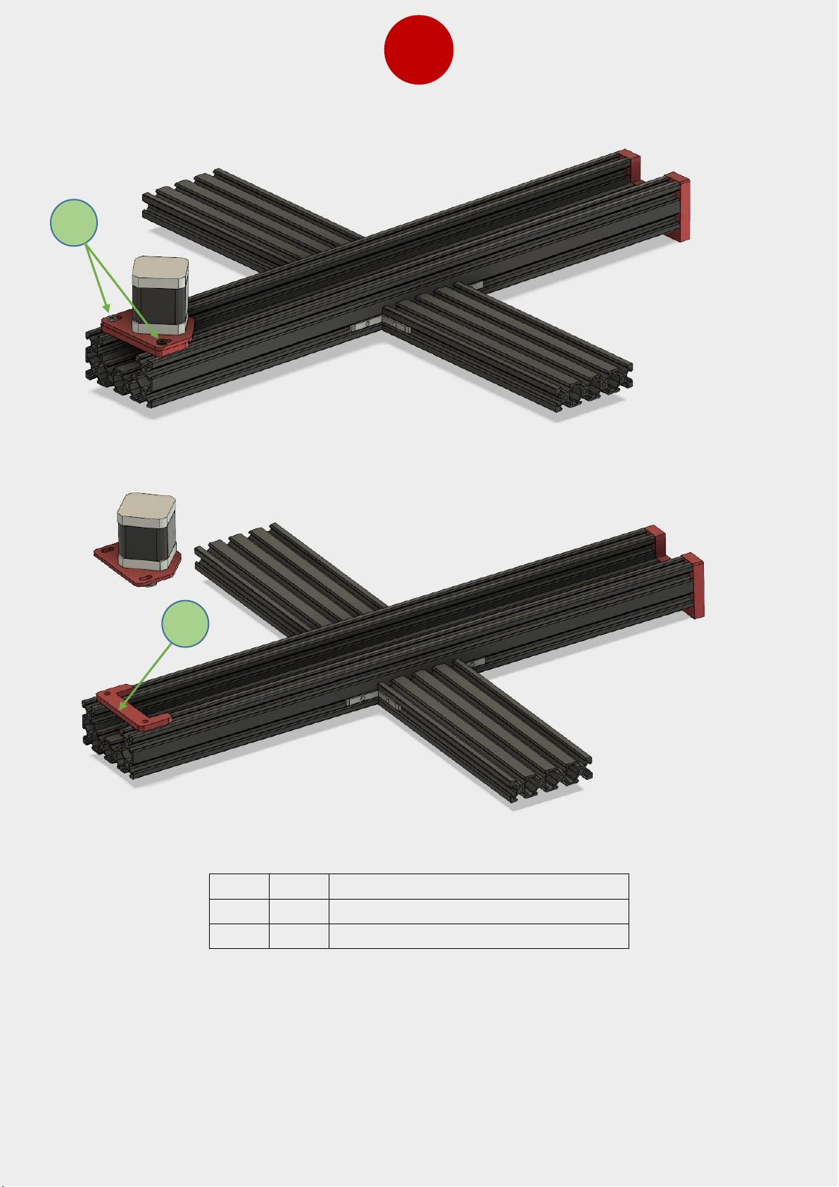
Put the Y motor and upper bracket on the lower bracket and use M5 bolts and T-nuts to
install on the extrusion. Leave 2 mm gap from the end of extrusions to allow tightening of
the belt later on.
Item
Qty
Part name
1 1 Lower Y bracket
2 2 M4x16 bolt
1
2
Page 11
9
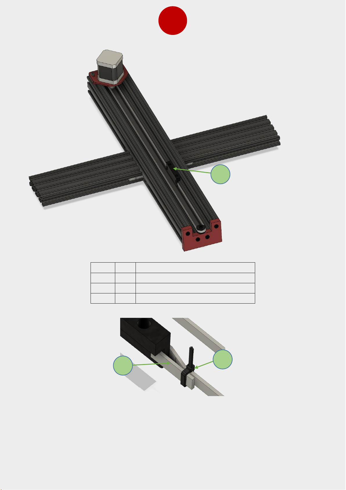
Item
Qty
Part name
1 1 Bed belt bracket
2 1 GT2 belt
3 2 Zip ties
Loop the belt around idler and GT2 pulley and put end of belt through holes in the part no
1. (Bed belt bracket). Install the bed belt bracket on the right side (looking from the front
otherwise the bed will move in the wrong direction. Use zip ties to tighten the loops. The
belt needs to be tight in this step, you will be able to adjust the belt tension by adjusting
the Y motor upper bracket.
1 2 1
Page 12
10
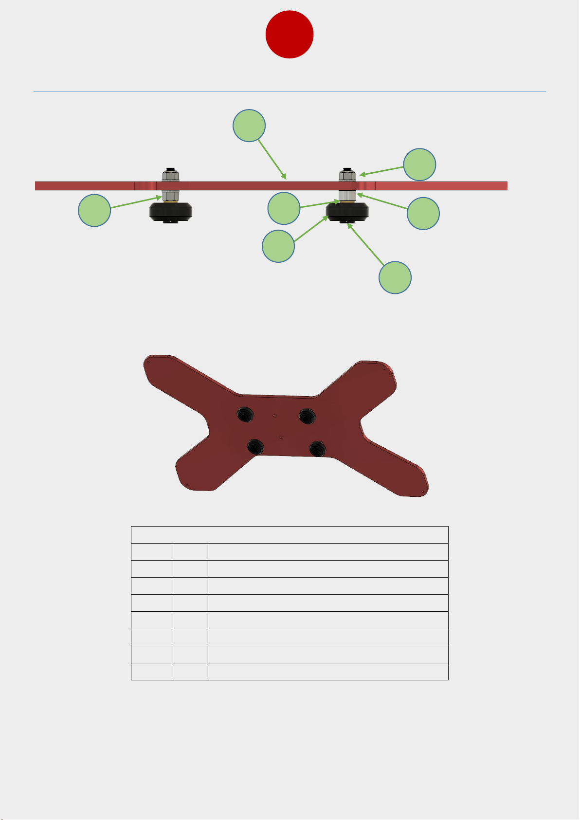
6. Bed Carriage Assembly
Bag Name: B-10
Item
Qty
Part name
1 4 M5 locknut
2 2 6mm spacer
3 4 8x5x1mm shim
4 4 V-slot wheel
5 4 M5x30 bolt
6 2 Eccentric nut
7 1 Heated bed carriage
2 3 1 4 5
6
7
Page 13
11
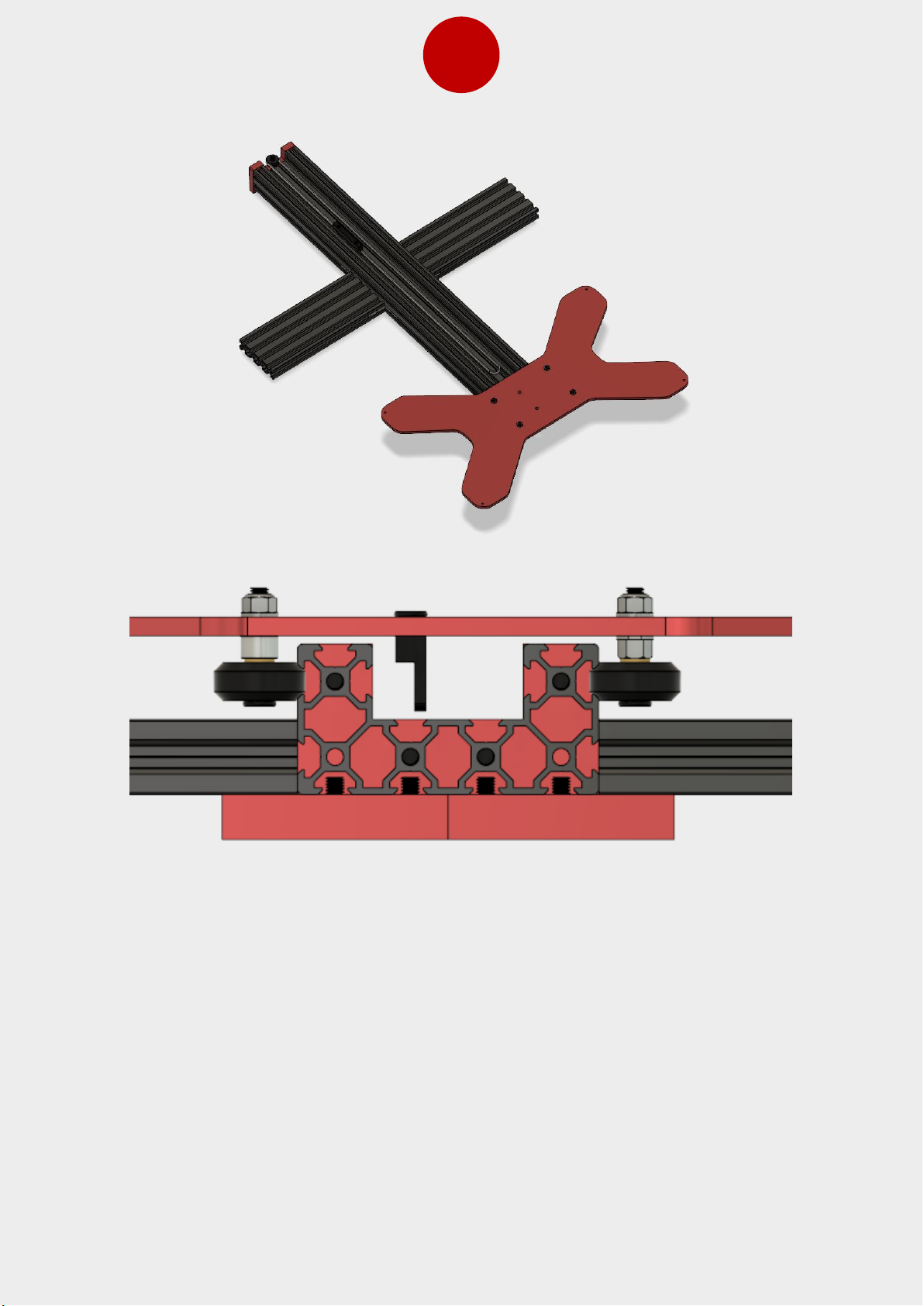
Remove the Y motor and brackets with the motor and slide the hotbed carriage in place.
Use the provided wrench to adjust the eccentric nuts to adjust wheels, so the carriage
moves smoothly in grooves. After this, use two M5 bolts to fasten the belt bracket in place
to bed. Mount the Y motor and brackets back in place and put belt back around the idler
and GT2 pulley. Slide the bracket with motor towards the back of the frame, so that belt
gets tensioned and tighten the bolts.
Page 14
12
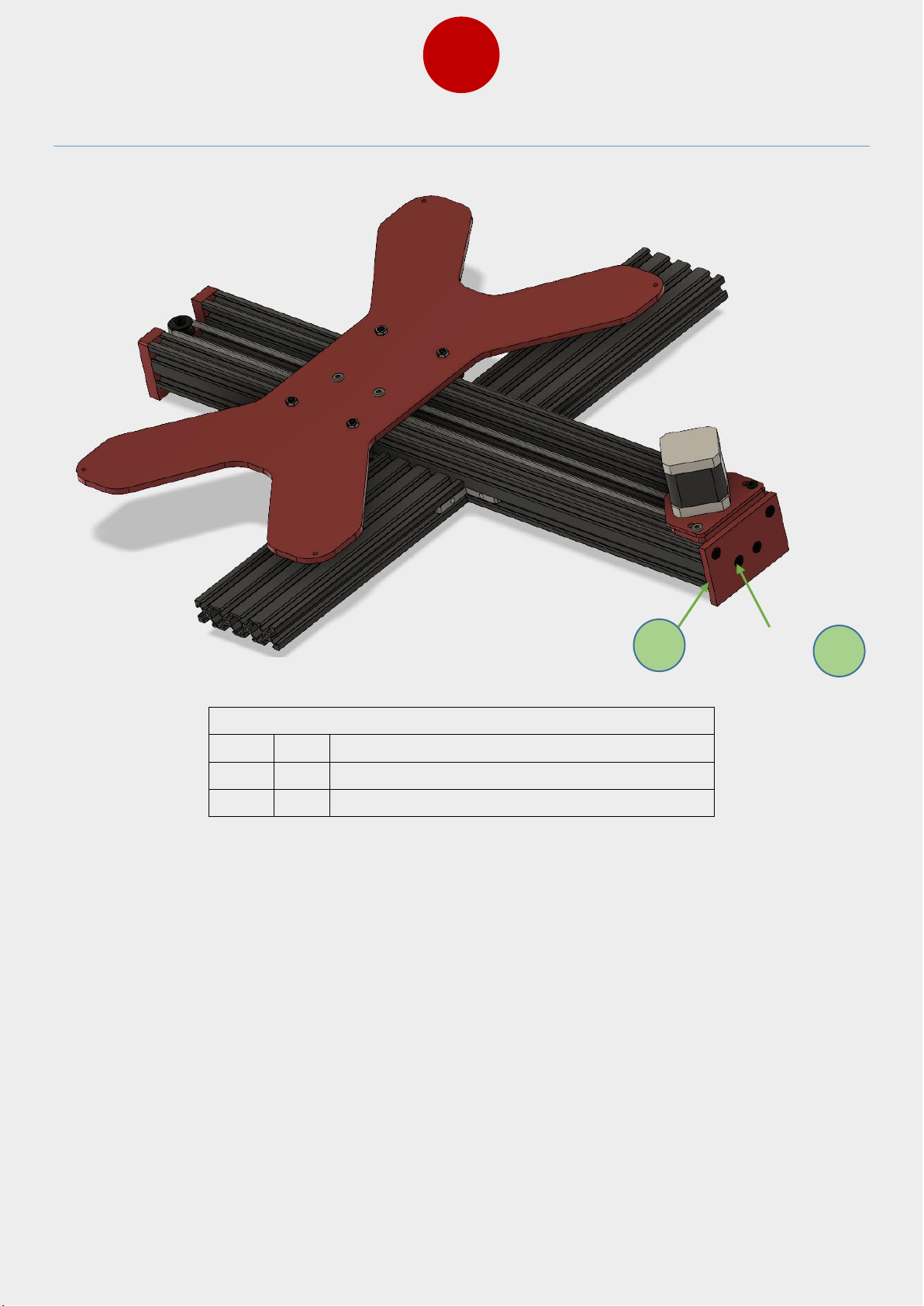
7. Second Y Endplate Assembly
Bag Name: B-2
Item
Qty
Part name
1 4 M5x20 bolts
2 1 Y axis endplate 2
1
2
Page 15
13
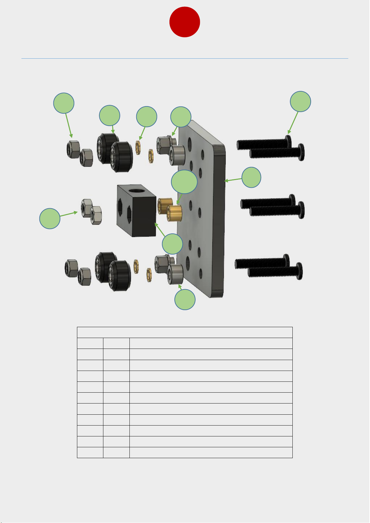
8. X Axis Assembly B-3, B-4
Bag Name: B-3, B-4
Item
Qty
Part name
1 4 M5 locknut
2 4 8x5x1 shim
3 4 V slot wheel
4 1 Z slide plate
5 2 Eccentric nut
6 6 M5x25 bolt
7 2 6mm spacer
8 2 M5 nut
9 1 POM trapezoid nut
10 2 5mm brass spacer
1 2 8
5 3 7
6
10
4
9
Page 16
14
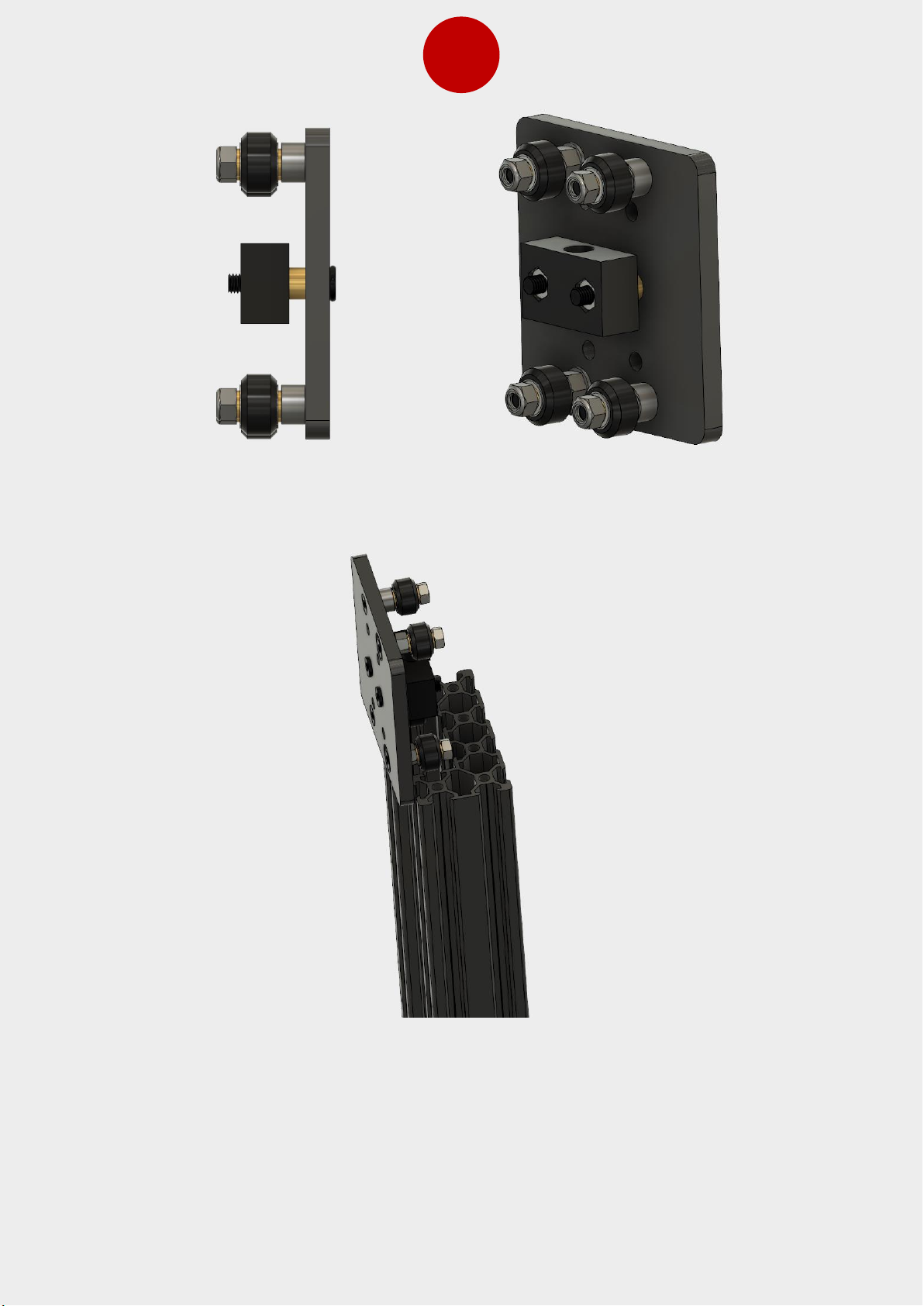
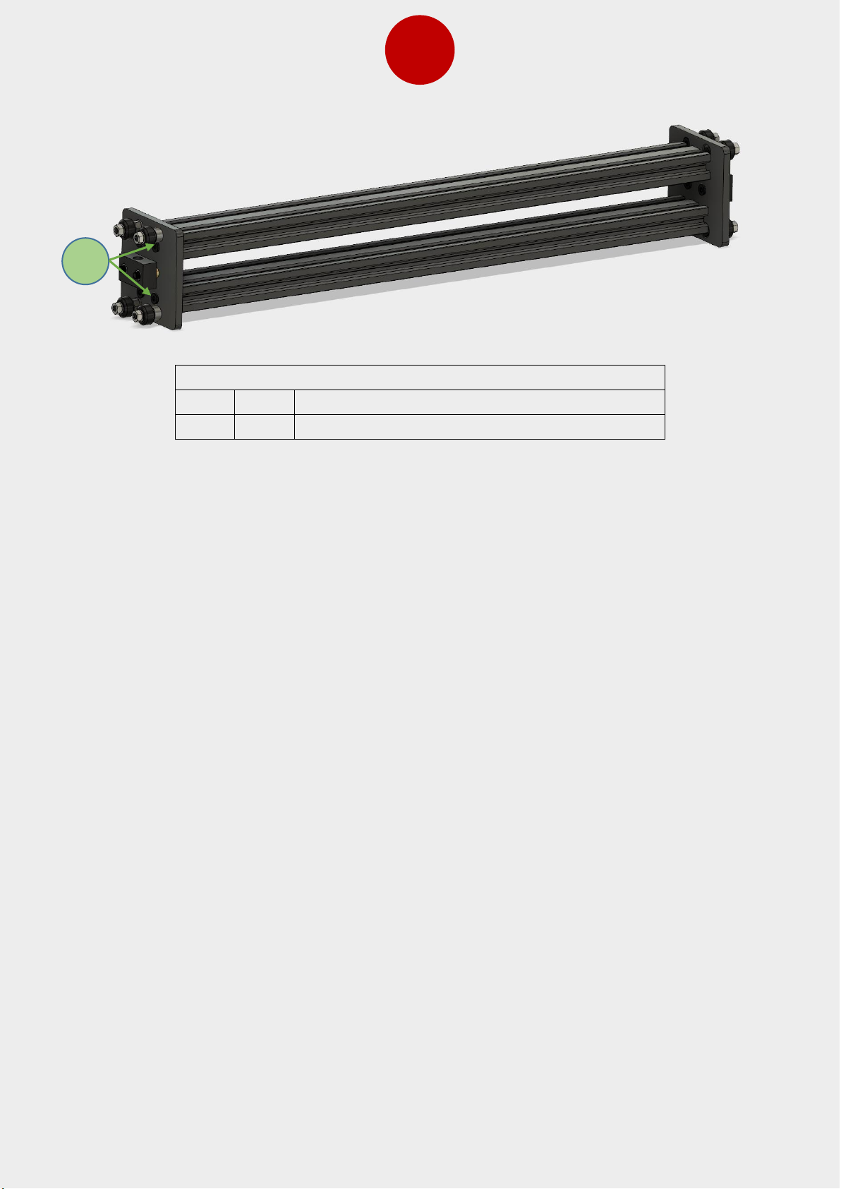
When you have both Z slides assembled, try them in the extrusions and adjust the eccentric
nuts so the wheel feels snug, but still rolls smoothly inside the extrusion.
Page 17
15
Bag Name: B-3, B-4
Item
Qty
Part name
1 8 M5x15 bolts
Assemble the X axis by mounting the Z slides to 2040 extrusions by using M5x15 bolts.
1
Page 18
16
9. Z Axis Uprights
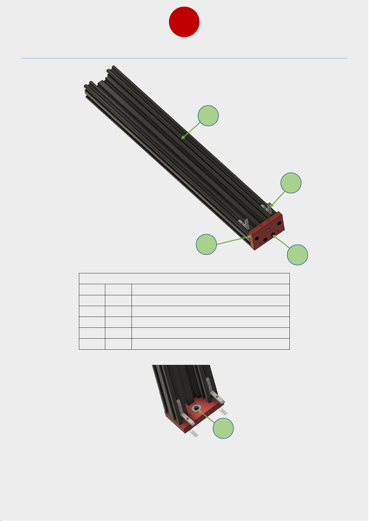
Bag Name: B-5, B-6
Item
Qty
Part name
1 2 C beam extrusion
2 4 L corner bracket
3 2 Z axis endplate
4 8 M5x20 bolt
5 2 Bearing
Prepare two pieces of the Z uprights as shown in above picture. Put bearing in the slot
located in the plate.
1 2 4 3 5
Page 19
17
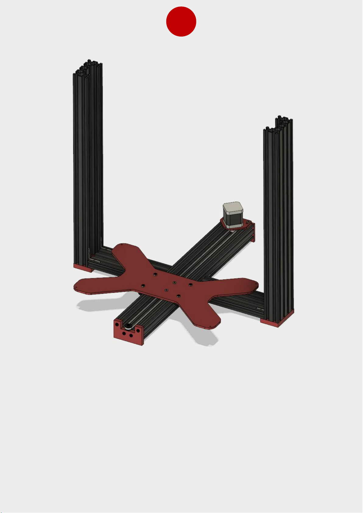
Install the Z uprights to the bottom frame and tighten in place. Make sure you use a square
to check squareness before tightening.
Page 20
18
10. Z Axis Assembly
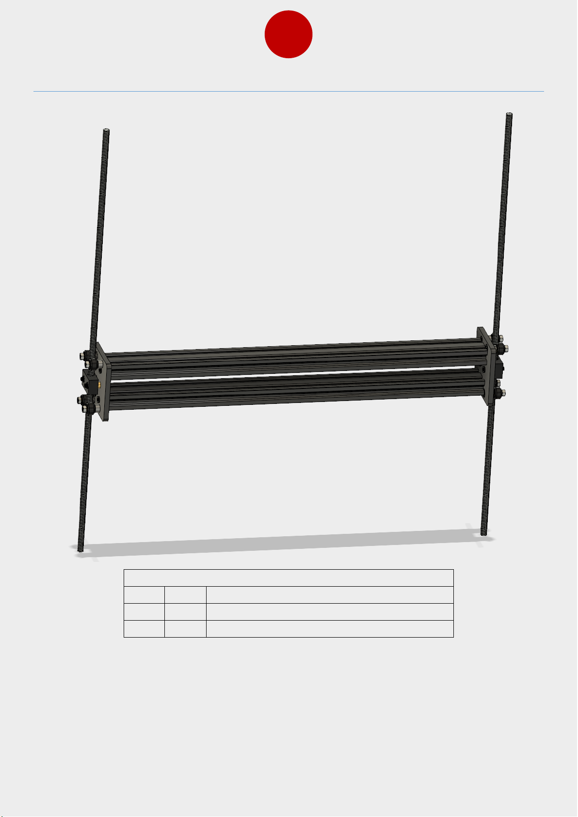
Bag Name: B-7, B-8
Item
Qty
Part name
1 1 X Gantry assembly
2 2 Z Rods
Screw the leadscrews in POM nuts as shown in picture above.
Page 21
19
Item
Qty
Part name
1 2 Lock collar
2 1 GT2 pulley
3 2 Loop Belt
4 1 Bearings
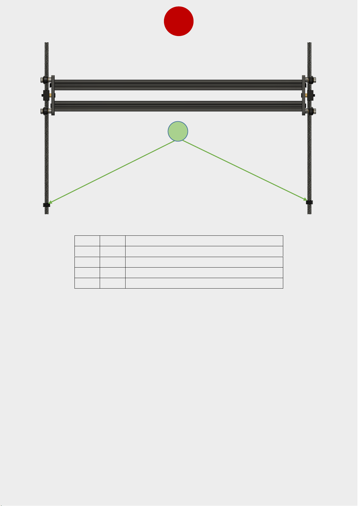
Fasten the lock collars in both leadscrews (around 5mm from bottom of screw). Next lower
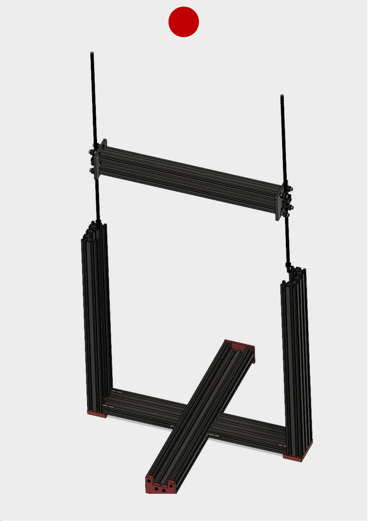
the assembly in the frame as seen picture in following page.
1
Page 22
20
Page 23
21
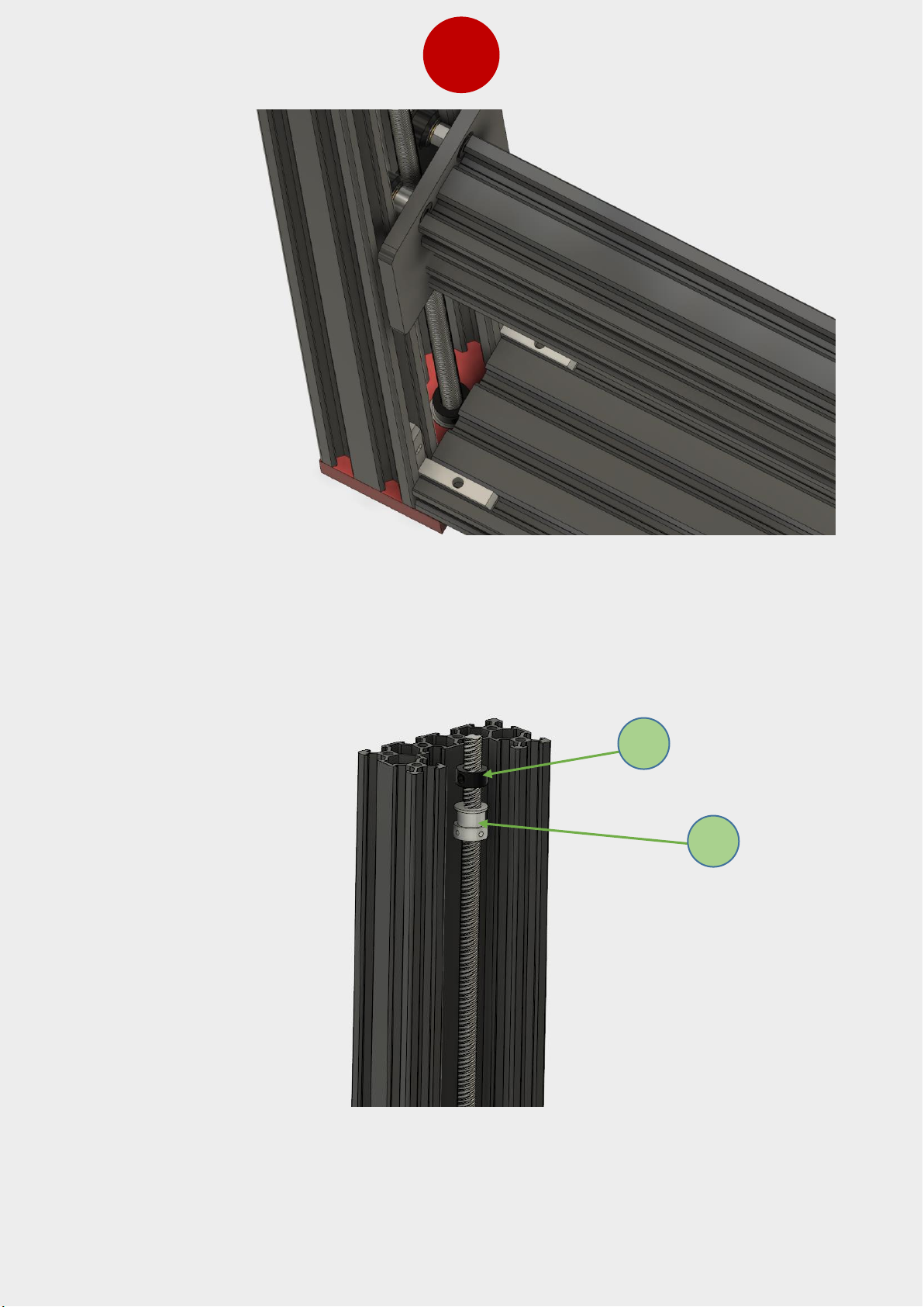
Make sure that the end of the leadscrews goes inside of the bearing and the lock collar
rests on top of bearing on both sides. After this you can install the GT pulley (item n.2) and
lock collar (item n.1) at the top of both leadscrews, see the photo below.
1
2
Page 24
22
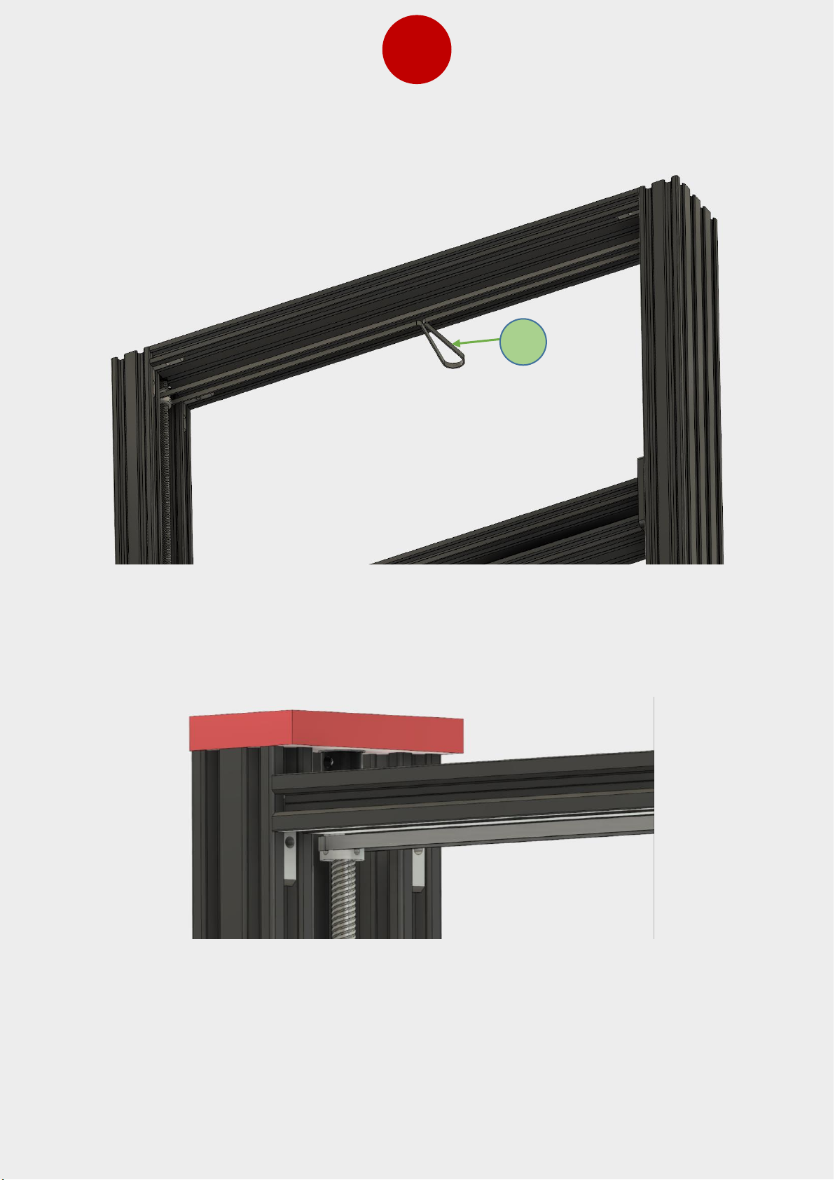
Put the looped belt in place and install the top 2080 extrusion as shown in the following
picture.
Install the red top Z plate in place by using M5x20 bolts and lower the top extrusion slightly
so you can firmly press and tighten the lock collar against the bearing in the plates in both
sides. After press top extrusion against the red plate and tighten the L bracket screws
3
Page 25
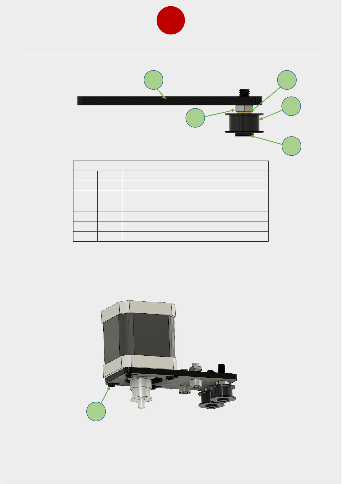
23
11. Z Motor Bracket Assembly
Bag Name: B-12
Item
Qty
Part name
1 2 M5x20 bolt
2 2 Idler
3 2 8x5x1 shim
4 2 M5 nut
5 1 Z axis motor bracket
6 4 M3x8 bolts
Build the Z axis motor bracket as shown in the above and following pictures. Use M3x8
bolts to attach motor to the bracket. Make sure you will not tighten the bolt too much so
that the idler can roll freely.
1 2 4 3 5
6
Page 26
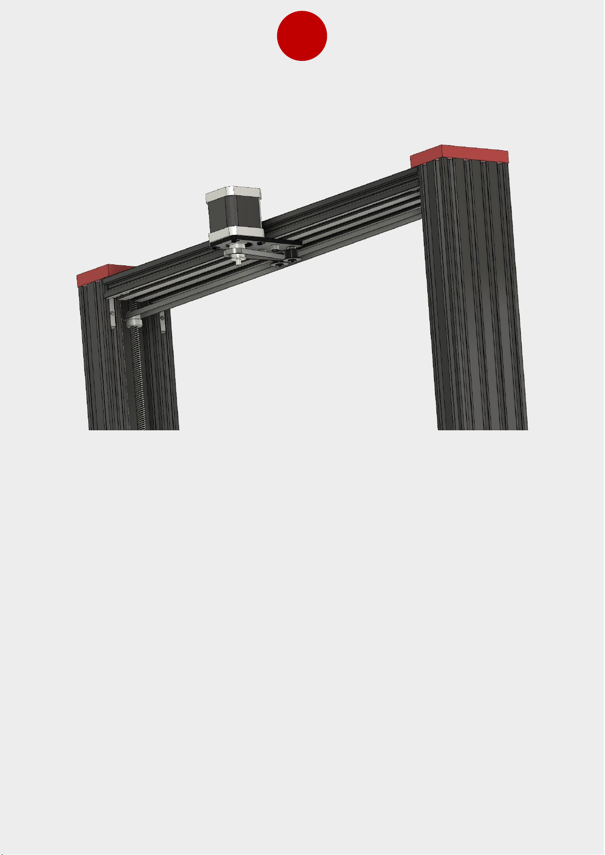
24
Install the Z axis bracket assembly in place and install the Z loop belt. You can tighten belt
by sliding motor towards back of the printer.
Page 27
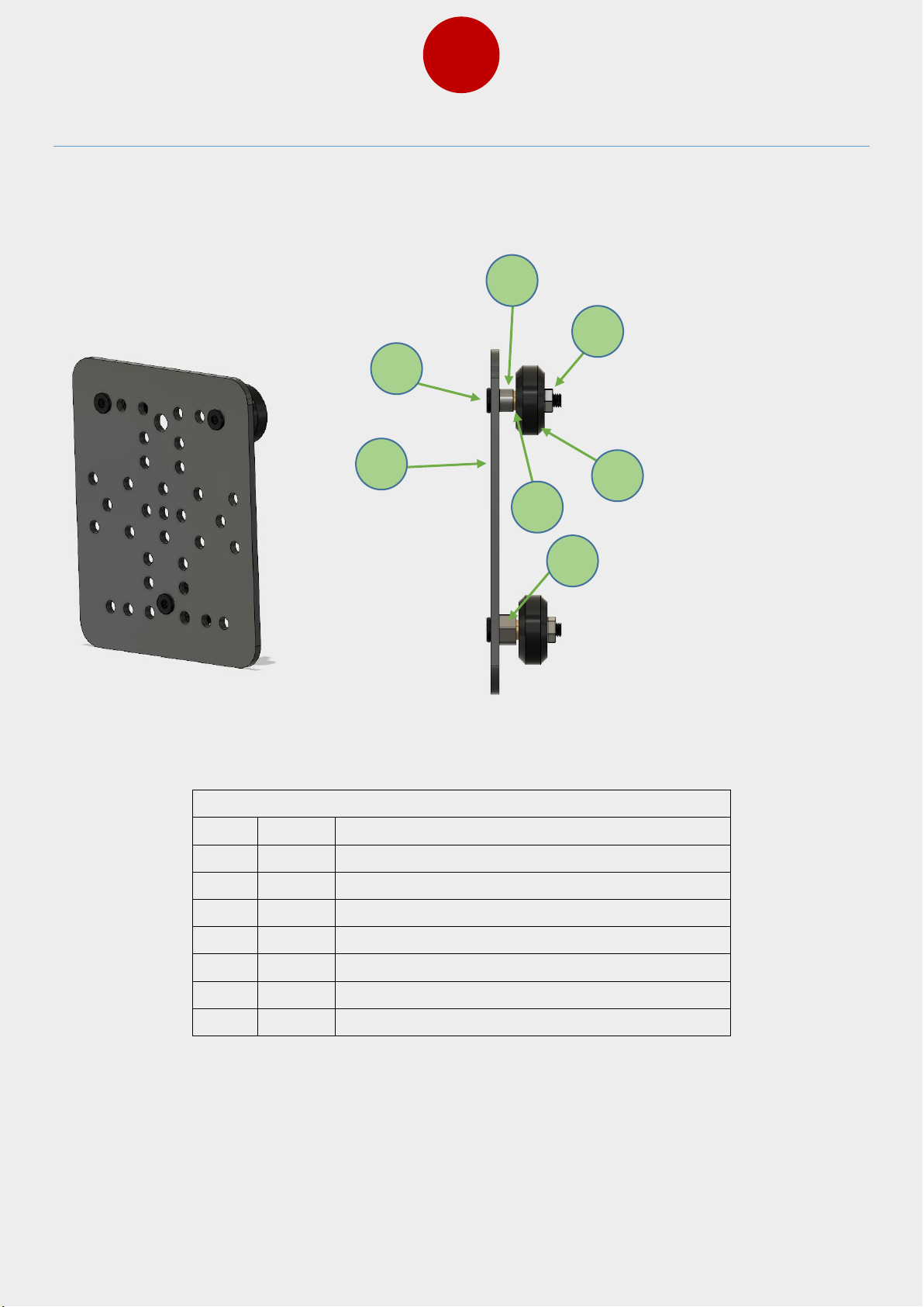
25
12. Extruder Plate Assembly and Installation
Bag Name: B-9, B-11
Item
Qty
Part name
1 1 Extruder plate
2 3 M5x25 bolt
3 2 6mm spacer
4 3 8x5x1 shim
5 3 V slot wheel
6 3 M5 locknut
7 2 eccentric nut
Start to assemble the extruder plate as shown in picture above and follow the assembly in
following pictures. Pay attention that you are using right holes when installing parts.
6 4 5
2 1 3
7
Page 28
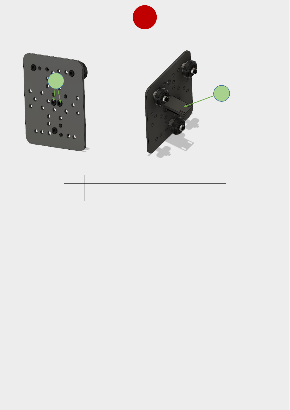
26
Item
Qty
Part name
1 1 X axis belt bracket
2 2 M5x15 bolt
1
2
Page 29
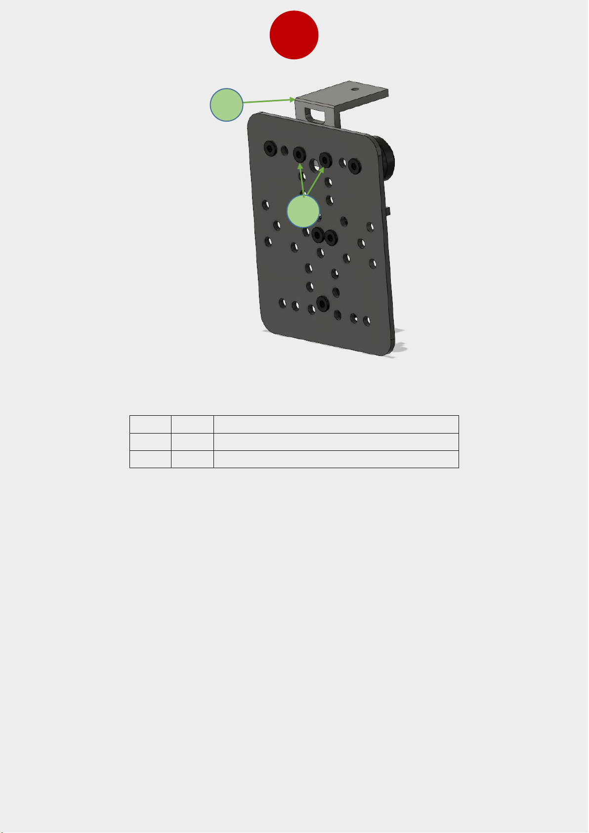
27
Item
Qty
Part name
1 1 Drag chain bracket
2 2 M5x15 bolt
1
2
Page 30
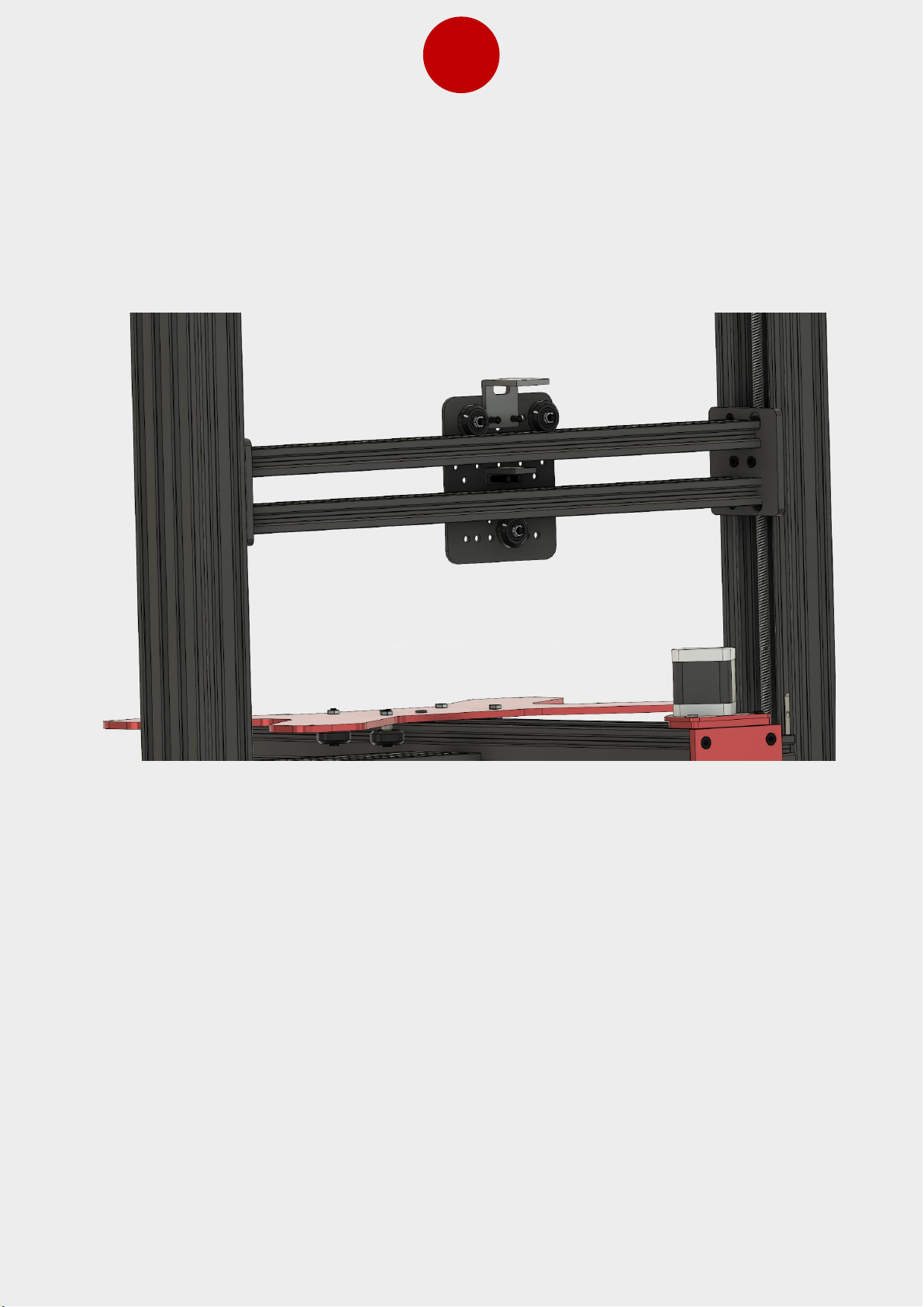
28
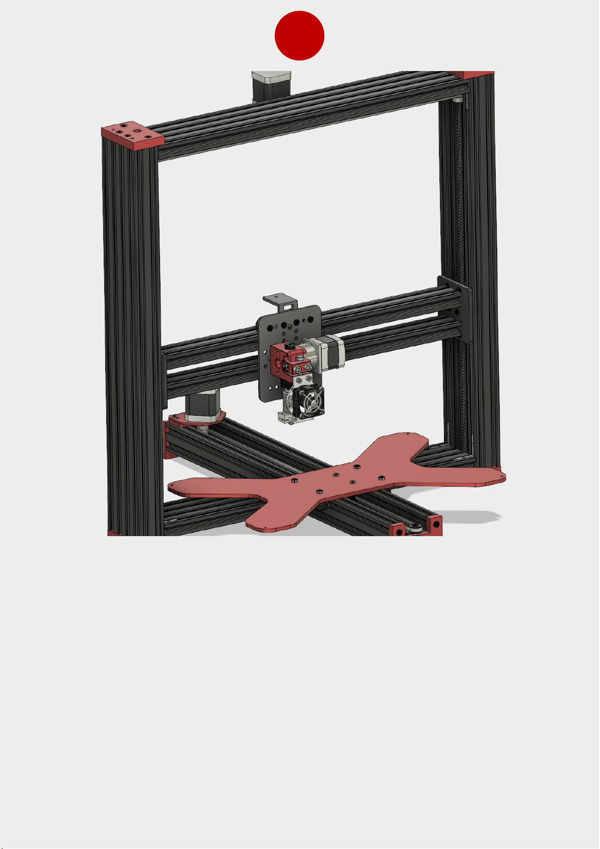
After extruder plate is assembled you can install it on X axis to make it easier you can
loosen the bottom screw with eccentric nut and put it back again when you have the plate
in place. Follow the same procedure as you did with the Z plate assembly to adjust the
eccentric nut.
Page 31
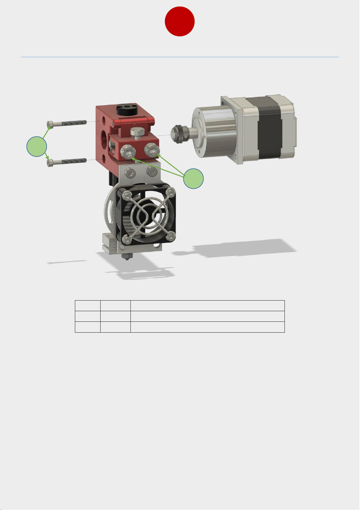
29
13. Extruder Assembly and Installation
Item
Qty
Part name
1 2 Adjustment bolts
2 2 M3x25 bolts
1
2
Assemble the extruder using two M3 bolts as shown in picture above. The two bolts shown
by number 1 is used to adjust the tension for the filament. These needs to be adjusted to
get the optimal grip on filament (example if the gear is turning but filament is slipping, you
need tighten these bolts).
Page 32
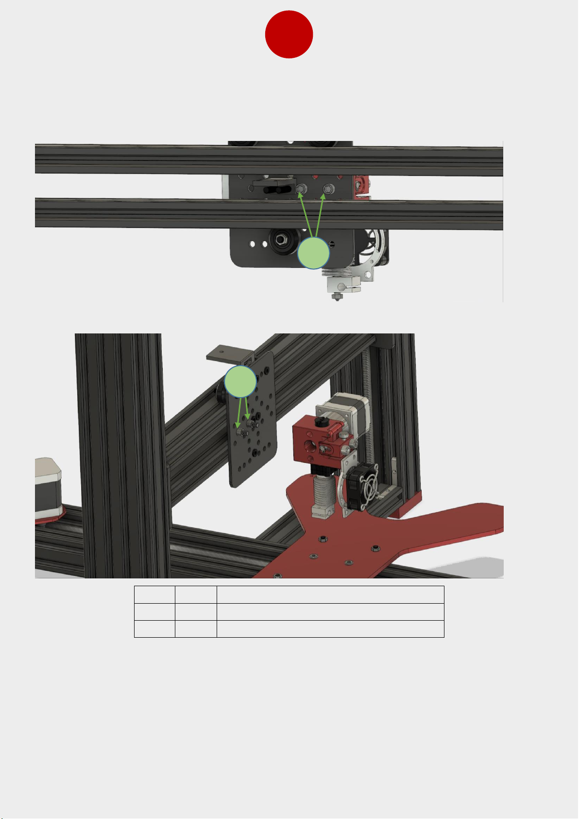
30
Item
Qty
Part name
1 2 M5x15 bolt
2 2 6mm spacer
Follow these pictures above to install the extruder.
1
2
Page 33
31
Page 34
32
14. X Motor and Belt Installation
Bag Name: B-19
Item
Qty
Part name
1 1 X axis motor
2 4 M4x16 bolt
3 4 M4 T-nut
4 1 X motor bracket
5 1 GT2 pulley
6 4 M3x8 bolt
7 4 6mm spacer
Assemble the X axis motor and bracket as pictured above.
3 2 4 1 6 5 7
Page 35
33
Item
Qty
Part name
1 1 X axis motor plate
2 1 M5x25 bolt
3 1 M5 locknut
4 1 8x5x1 shim
5 1 Idler
6 2 M4 T-nut
7 2 M4x10 bolt
3 7 6 5 2 4 3
1
Page 36
34
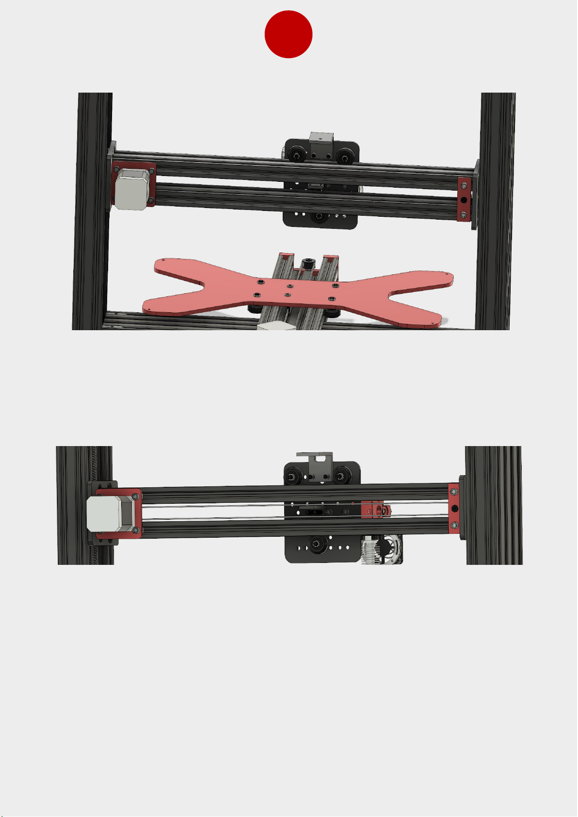
Install the motor with bracket and idler as shown in the picture above. After that, loop the
belt around idler and GT2 pulley in motor shaft and put the loose ends through the belt
bracket on the extruder plate and use zip ties to close the looped ends
Page 37
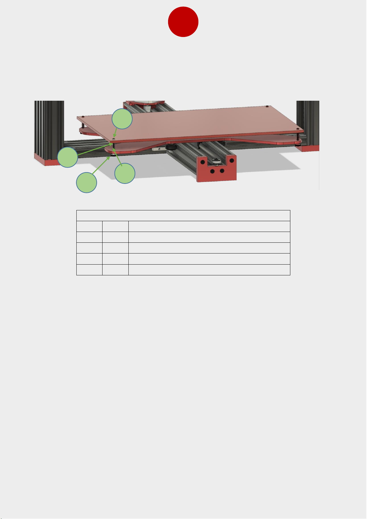
35
Install the heated bed as shown in following picture, so that cable connector faces the back
of the printer. Place the non-conductive spacer between the bed and the spring.
HOT BED SCREW
Item
Qty
Part name
1 4 M3 “thumb” nut
2 4 spring
3 4 M3 bolt
4 4 M3 non-conductive spacer
2
1
3
4
Page 38
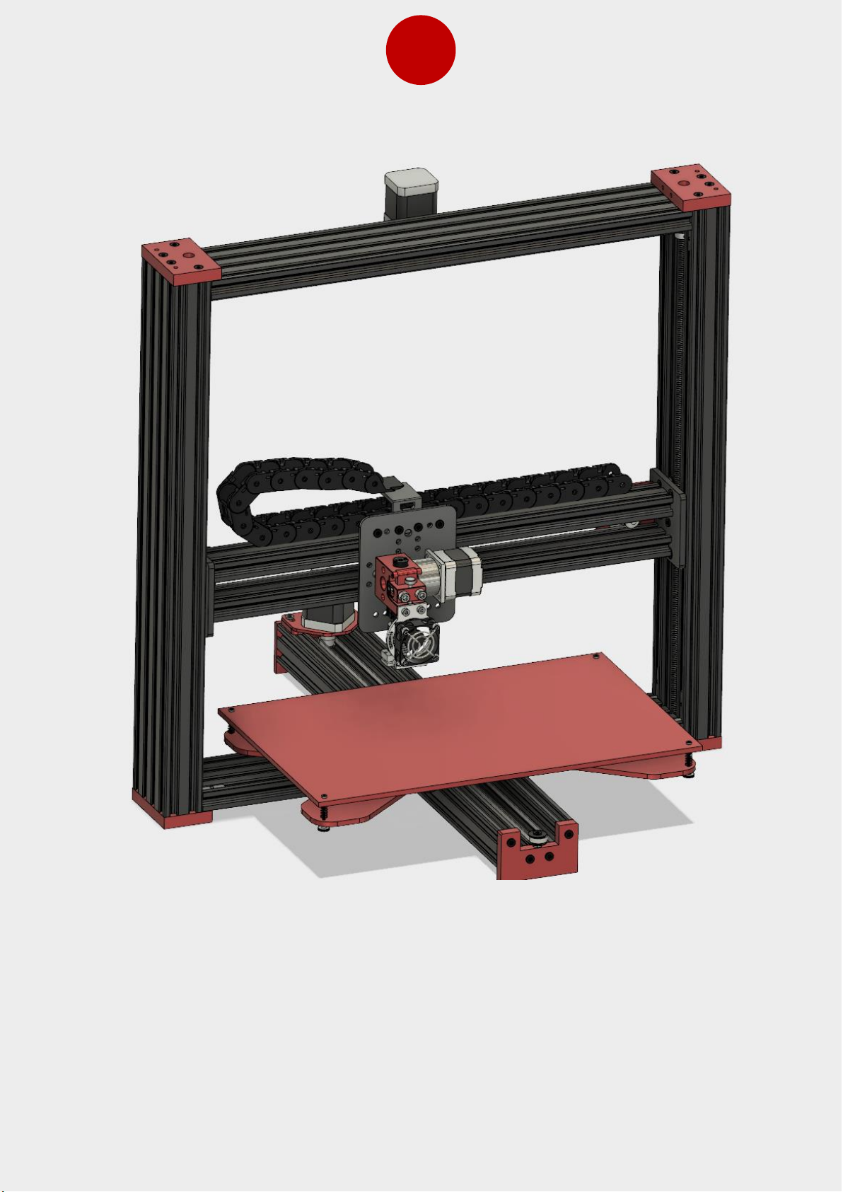
36
Install the drag chain in place on top of X axis extrusion.
Page 39
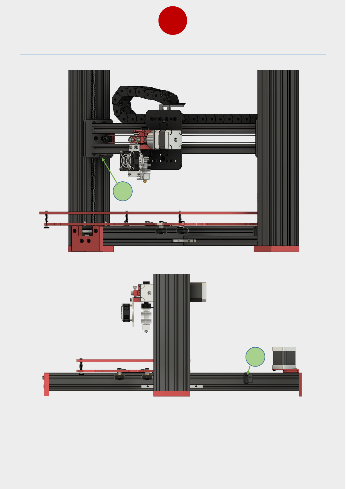
37
15. Limit Switch Installation
1
2
Page 40
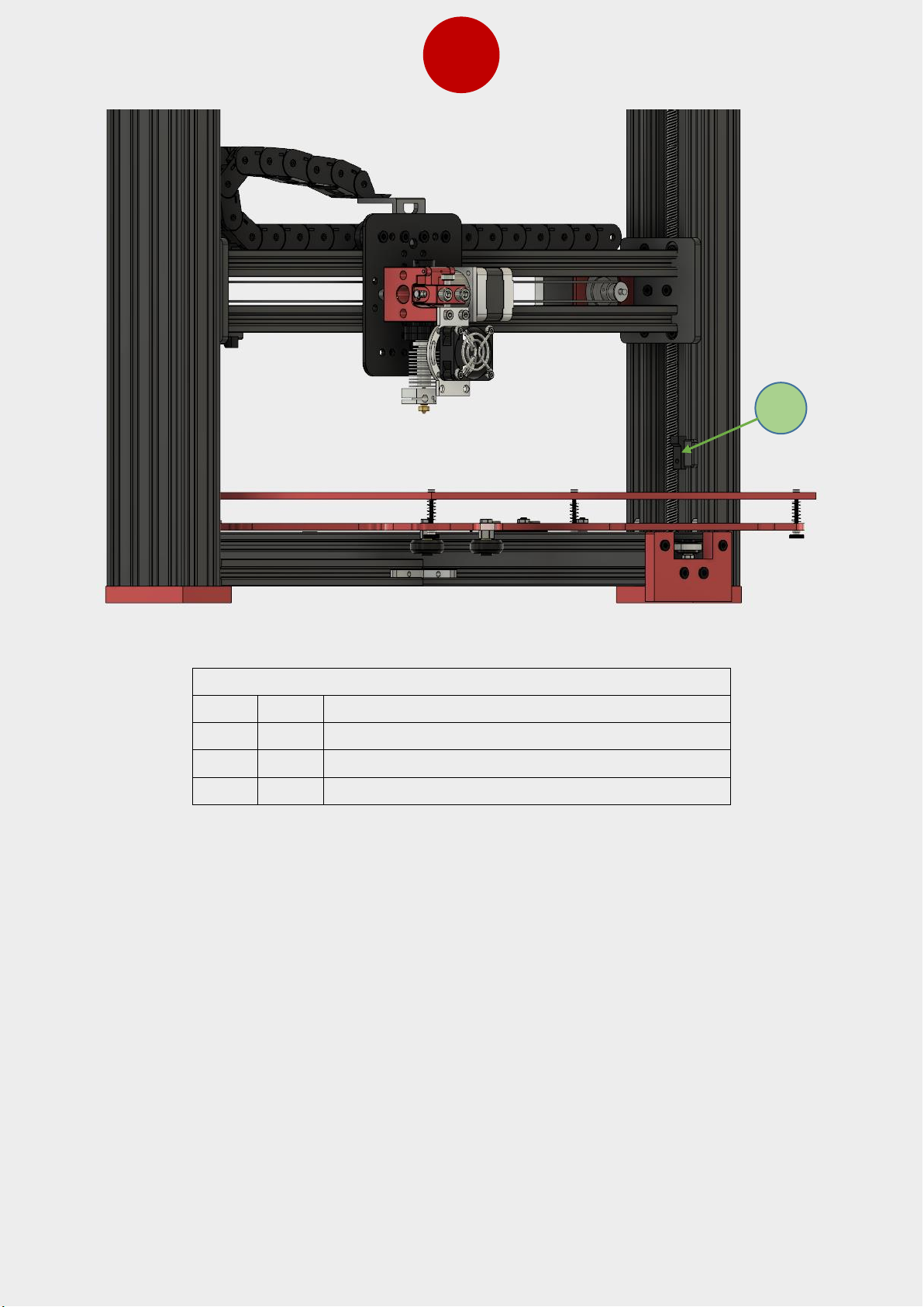
38
Bag Name: B-14, B-15, B-16
Item
Qty
Part name
1 1 X axis switch
2 1 Y axis switch
3 1 Z axis switch
Install the limit switches as shown in the pictures above.
3
Page 41
39
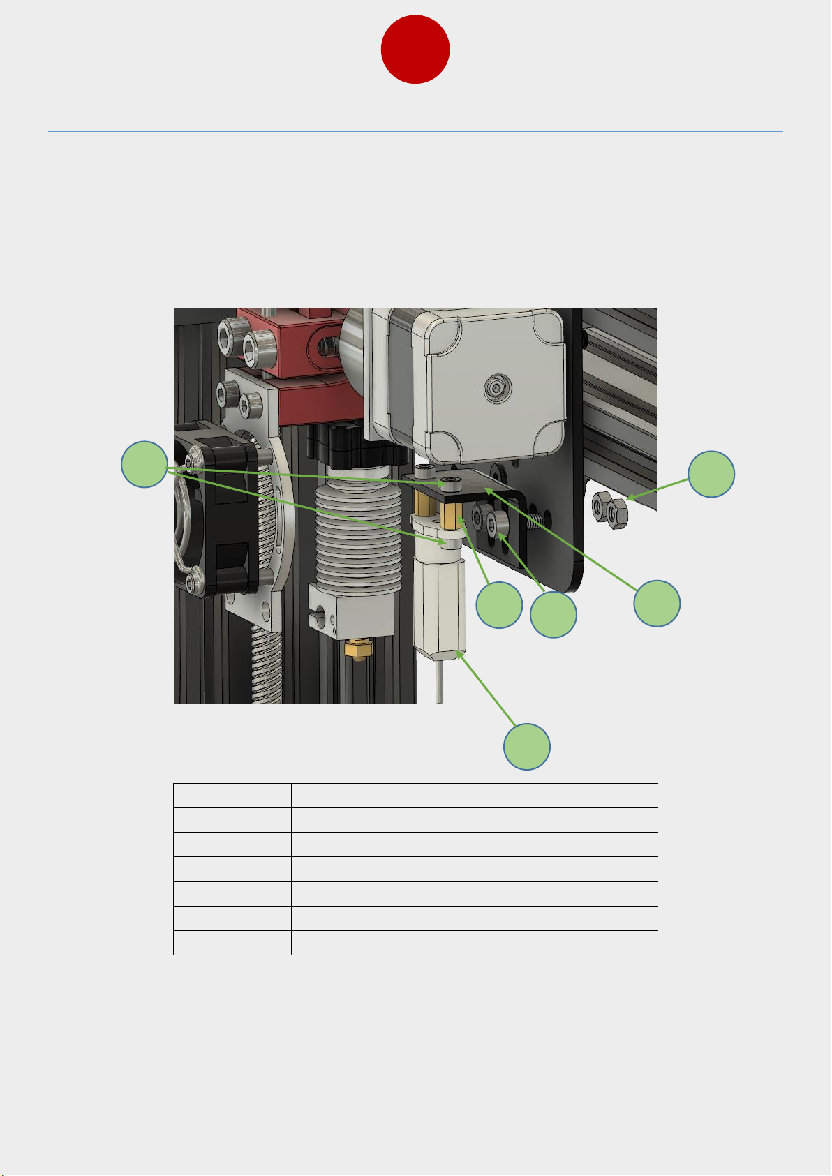
16. Bltouch Installation Instructions (Optional)
If you have printer with BLtouch option, then follow the following picture to install it on the
printer. The bracket of BLtouch can be adjusted up and down as needed and you should
adjust it so that the BLtouch pin will go back in before nozzle hits bed. (When the pin is
ejected it should be around 2mm lower than the nozzle and when it is retracted it should
be higher than nozzle so that it won’t hit the printed part).
Item
Qty
Part name
1 1 BLtouch
2 1 BLtouch bracket
3 4 M3x6 bolt
4 2 M3x8 brass spacer
5 2 M4x10 bolt
6 2 M4 nut
6
1 3 5 4 2
Page 42
40
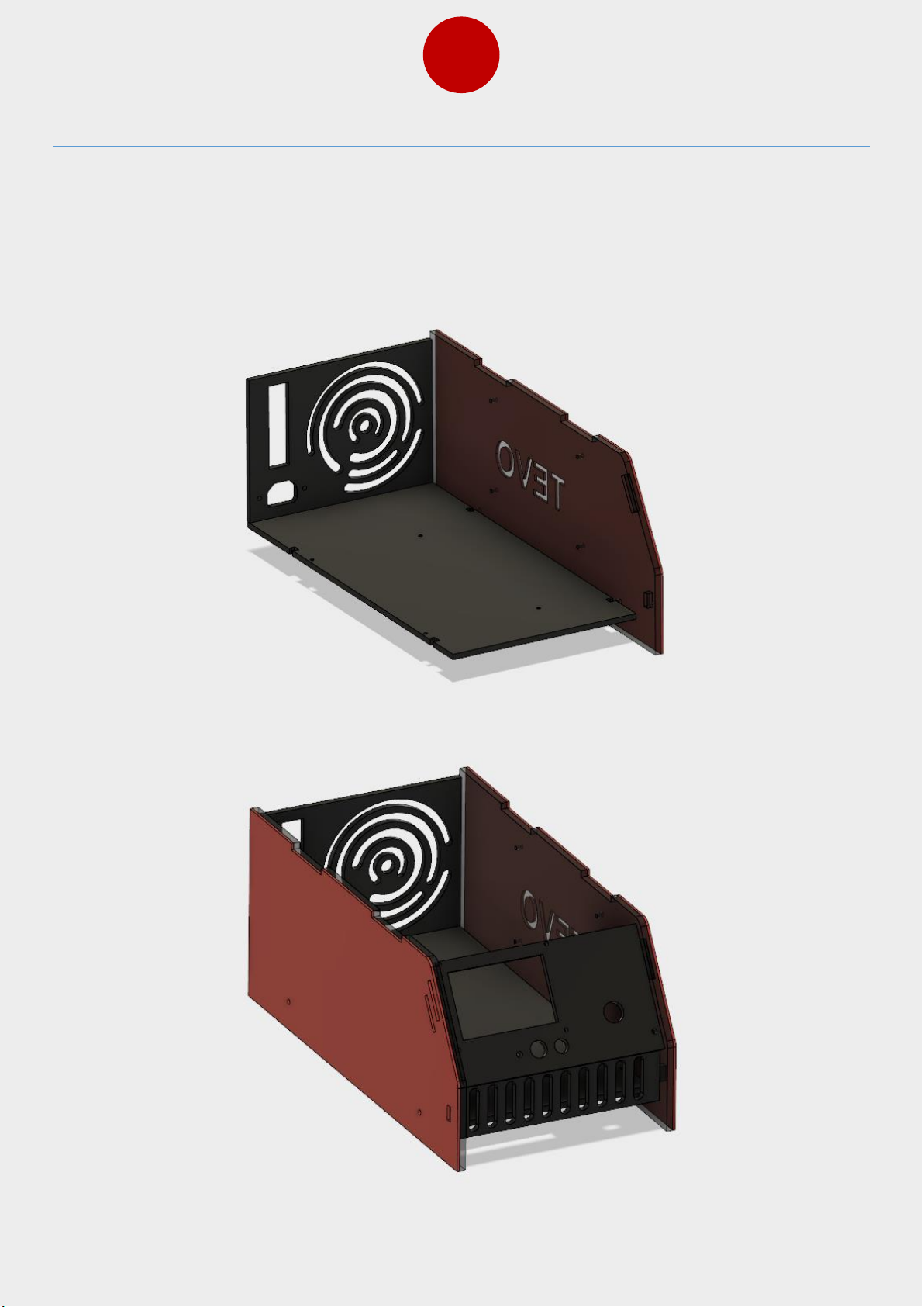
17. Control Box Assembly
Assemble the control box as shown in following pictures by using M4x12 bolts and M4 nuts.
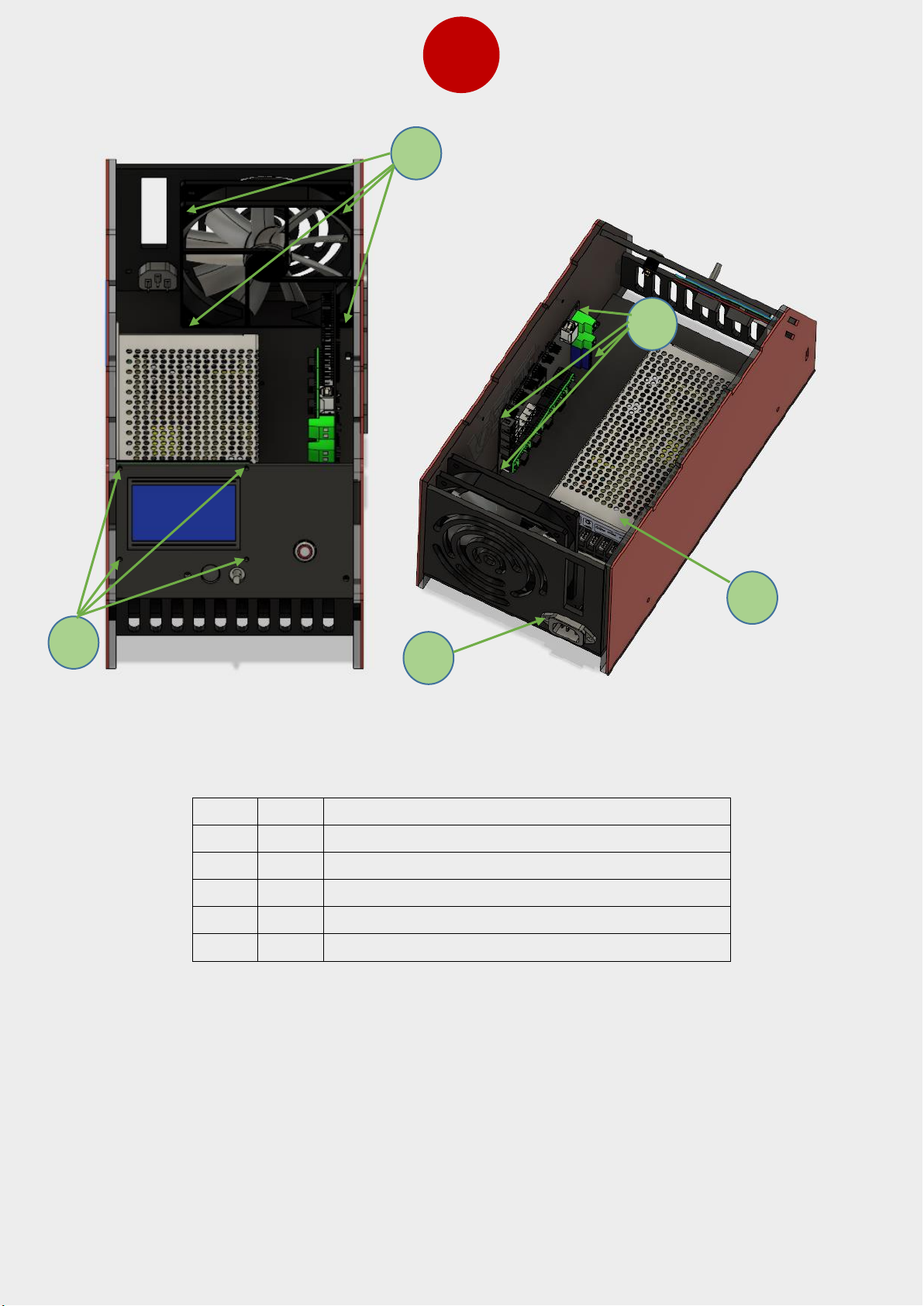
Install the PSU, LCD, mainboard and fan in box by using spacers provided within the kit. Use
M4x12 bolts and M4 nuts to assemble the casing.
Page 43
41
Item
Qty
Part name
1 4 M3x45 bolts + M3x8 spacers and M3 nuts
2 4 M3x20 bolts and M3 nuts
3 4 M3x20 bolts + M3x8 spacers and M3 nuts
4 2 M3x10 bolts and M3 nuts
5 4 M4x8 bolts (for power supply)
3 2 1 4 5
Page 44

42
18. Mainboard Connections
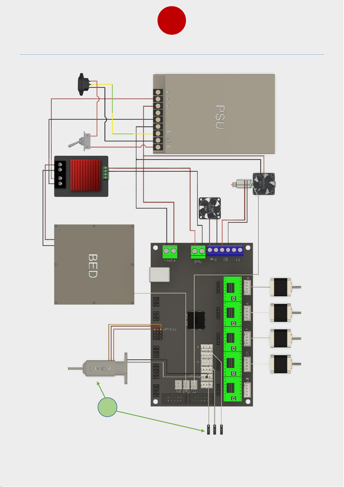
Connect the mainboard according the next page wiring schematic. The fan connection is
meant for print cooling fan (not for the hot end cooling fan, which should be connected
directly to 24V). When wired properly your printer should now be ready to be powered up.
Please check all cables again before connecting the power supply unit to AC power. While
powering the printer for the first time, you should have your hands on the On/Off switch,
switch the power off when the printer does not move into the front left corner. Also not
the following screen schematic (Item N.1) that BLTouch is optional and if you install
BLTouch then you will not use the regular Z sensor.
Page 45
43
19. Wiring Schematic
1
Page 46
44
20. Setting Up Repetier-Host for Printing
This printer works with most slicing/printing software like Simplify 3D, Cura, Repetier-Host,
etc. But we will go in details for Repetier-Host software and tell you how to set it up so that
you can make your first print. First, we recommend you to download the Repetier-Host
from their website: https://www.repetier.com/
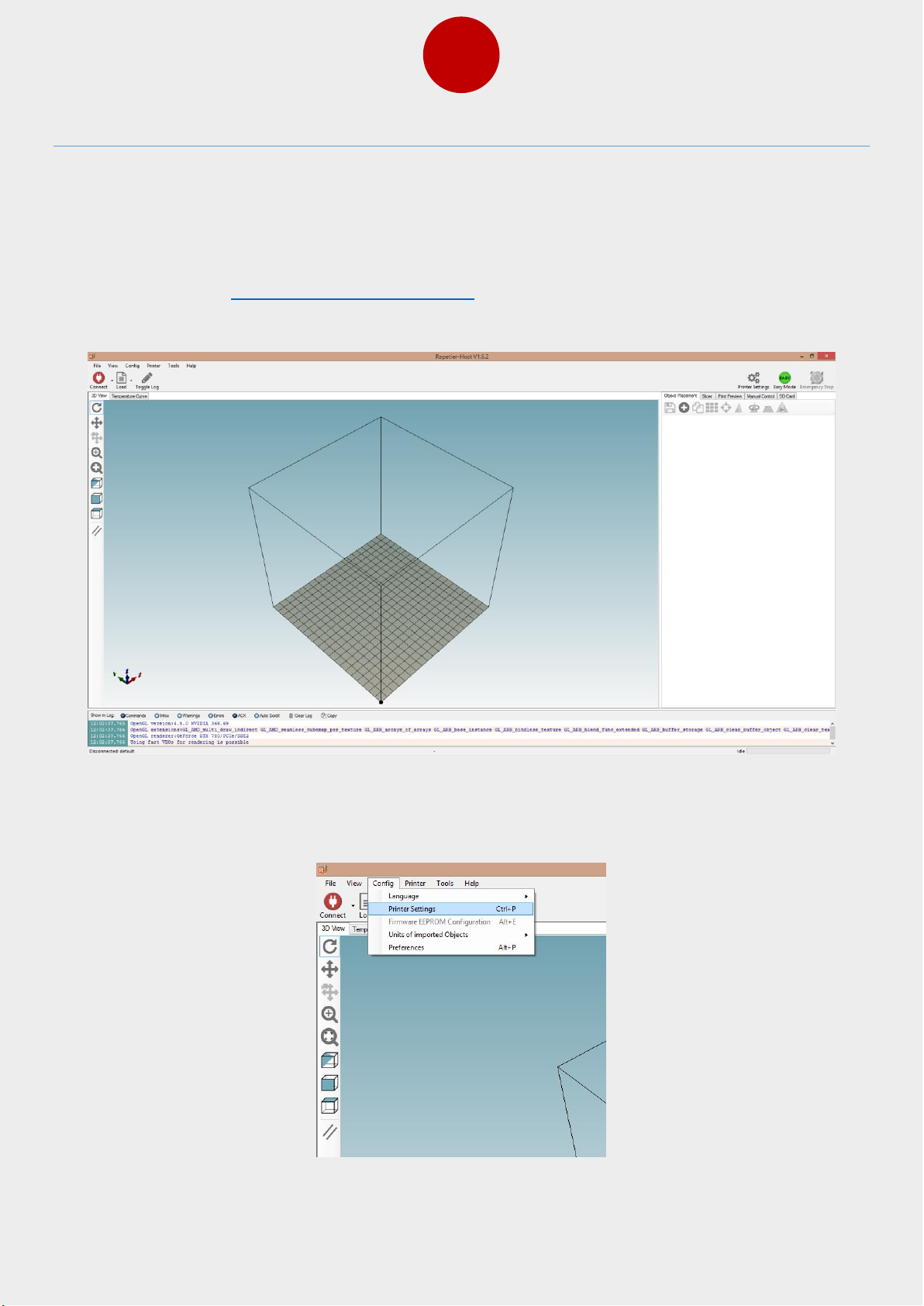
After installation is done and you start the software, you should get following screen:
Now we have to set up our printer in the settings so that Repetier-Host can connect to it
and will know what size of build area our printer use the slicer software will know the build
area size. Use the following picture (click Config->printer settings)
Page 47
45
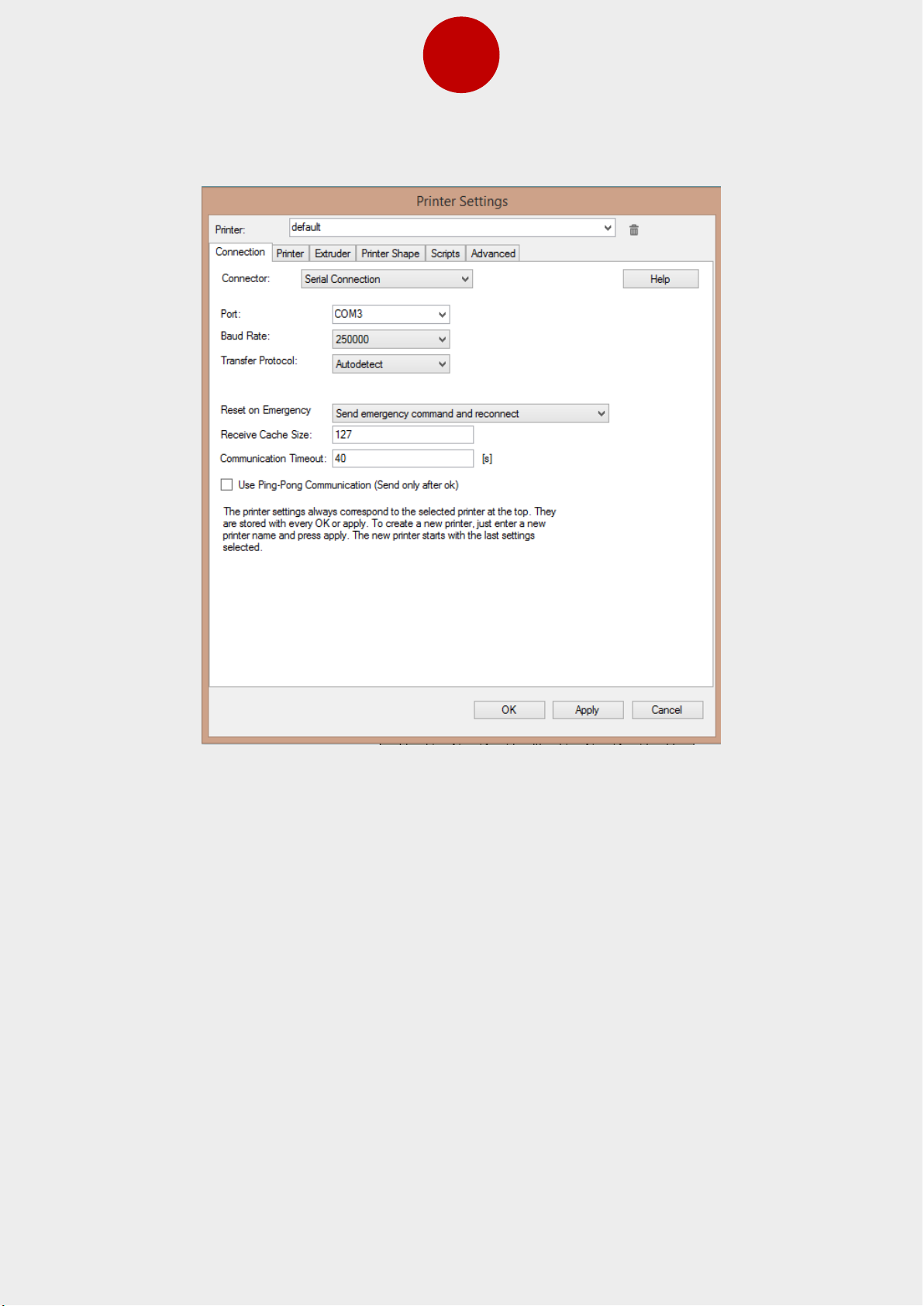
You should get following screen:
First set Port: to whatever port your mainboard uses (when you have connected your
printer to PC it should show up in here). Set “Baud Rate:” to 250000 and don’t touch any
other settings in this tab.
Page 48
46
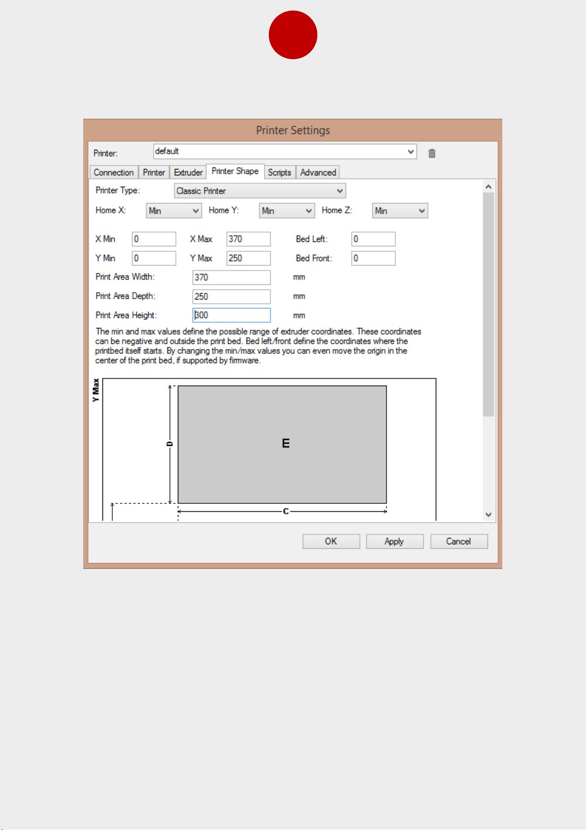
After this click tab “Printer Shape” and you will get following screen:
Set the values according to the picture above.
Page 49
47
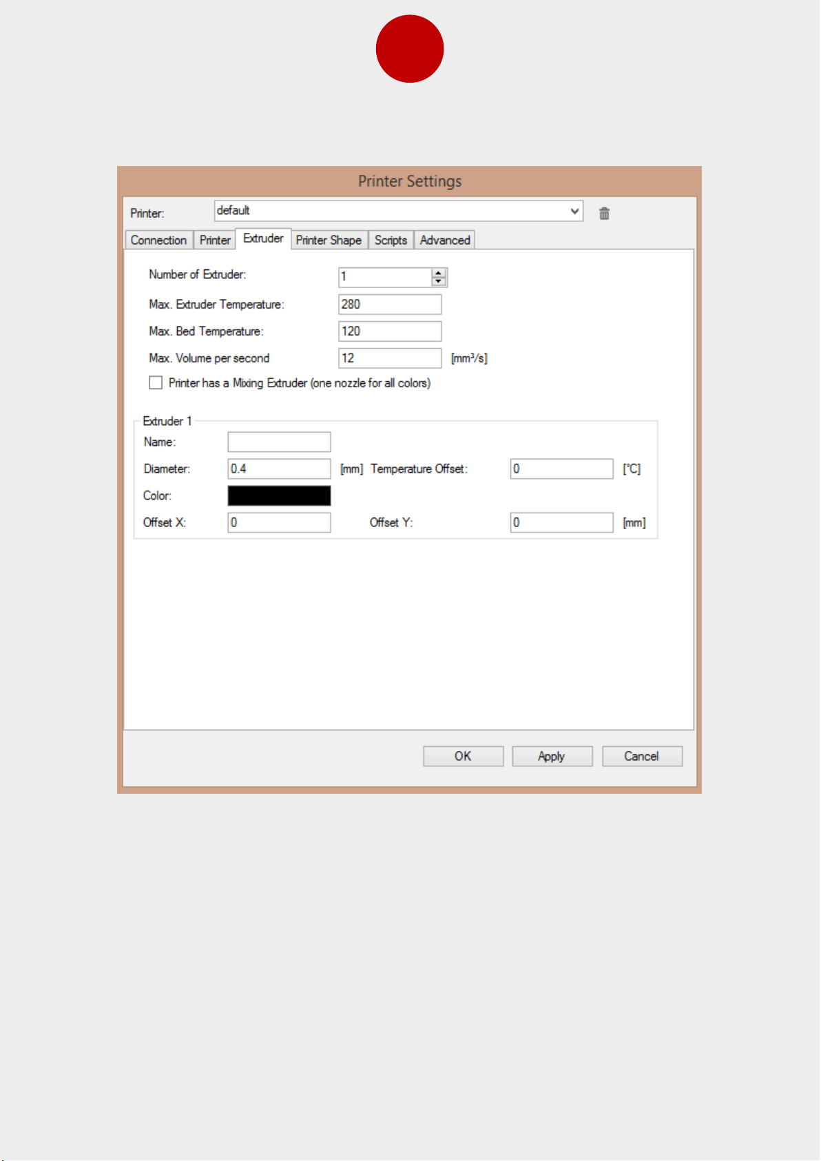
Next click tab: “Extruder” and set the values as shown in following picture
You can set the “Color:” by clicking it and just choosing color. The color won’t affect any
way in printing as it just shows the imported model in this color
Page 50
48
21. BLTouch Calibration (only if you have BLTouch option)
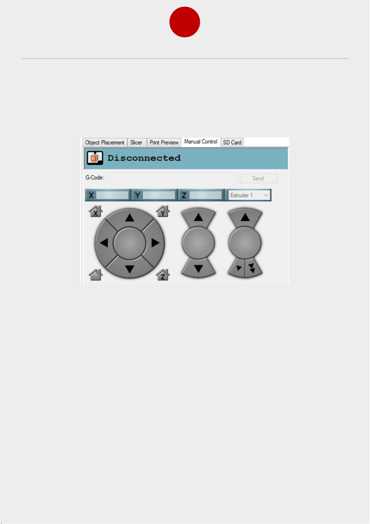
One of the first things to do before printing is to calibrate BLTouch sensor, so that nozzle
distance from the bed will be correct. We recommend doing this from Repetier-Host. Open
Repetier-Host and connect to the printer. After this, select “Manual Control” tab and you
should see “G-Code:” field as in following picture. Write in this field “M851” and press send
button.
Write down the value you will see in the bottom screen of Repetier-Host (Repetier log) and
next send following command “M851 Z0” and after that “G28” and at last send “G1 Z0”.
After this, the LCD screen of printer should show that the position of Z axis is zero “Z=0”.
Now you have to use the printer’s own controller (LCD screen) and go to the menu and
from there “Prepare/Move axis/0.1mm/Move Z”. Move the Z axis slowly down until the
nozzle is the right distance from the build plate (A4 paper will feel just little resistance when
moving it under the nozzle). Take a note of Z value that is shown in LCD screen (it should be
negative value and let’s presume it is -1.1). Next send G-Code “M851 Z-1.1” (remember to
use your own value you wrote down from screen) and send G-Code “M500” to save the
changes and you are done with the calibration.
Page 51
49
22. Slicer Settings for Repetier-Host
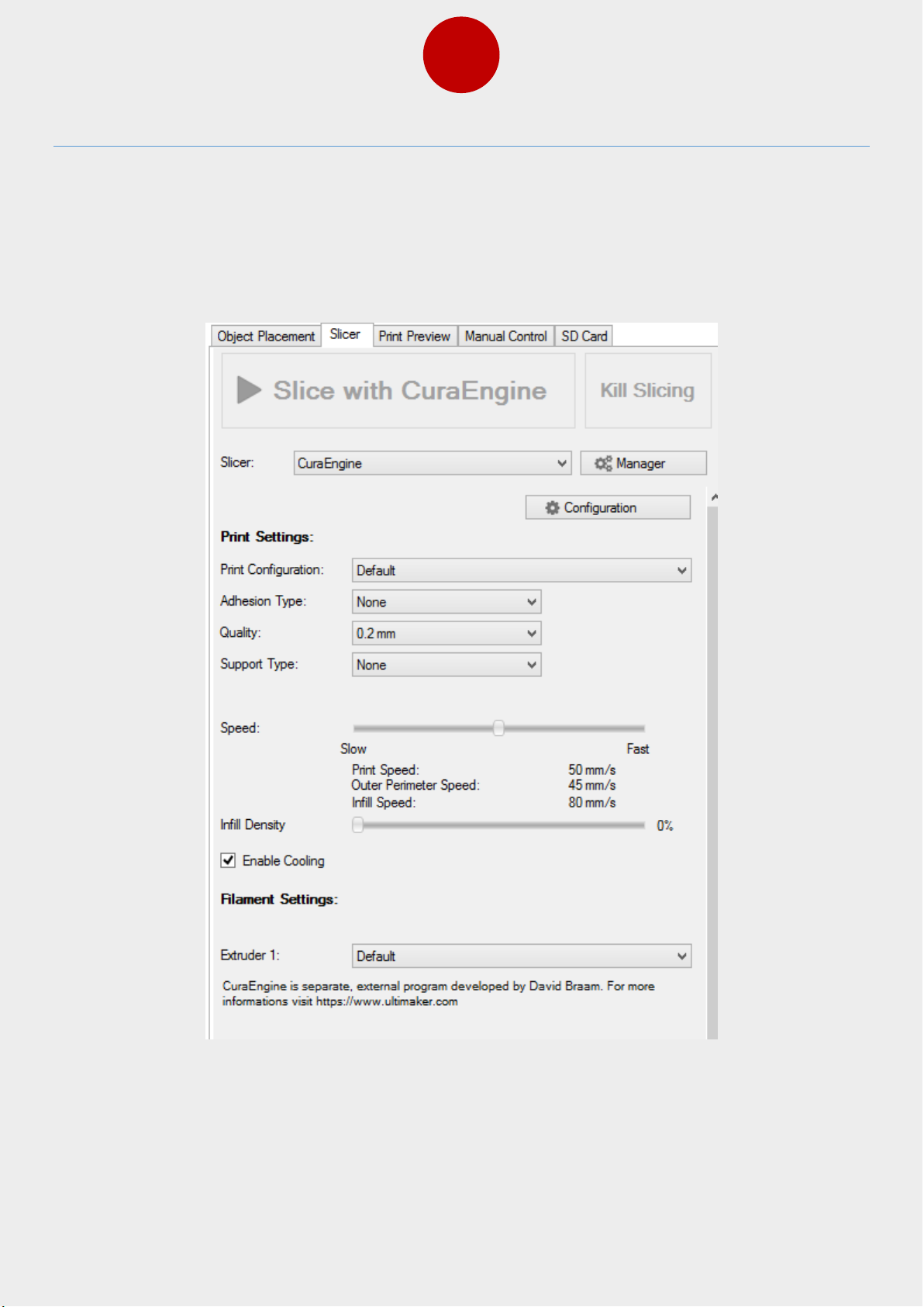
For Repetier-Host you can use several slicers, but we will show how to set the CuraEngine.
On the right side of main screen, click on the tab “Slicer” and select CuraEngine as shown in
following screen. Then click button “Configuration”
Page 52
50
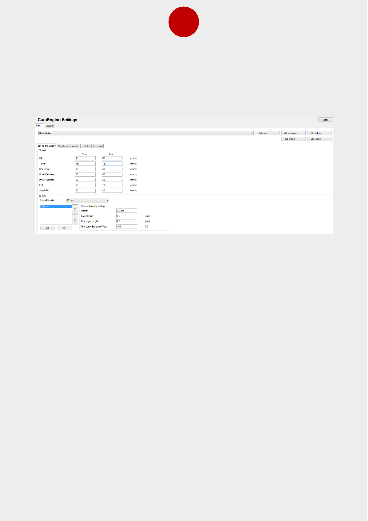
You will get following screen. Click on button “Import” to import our settings for printer and
select the saved file BlackWidow.rcp (It should be on the SD following the printer)
Page 53
51
23. First Test Print
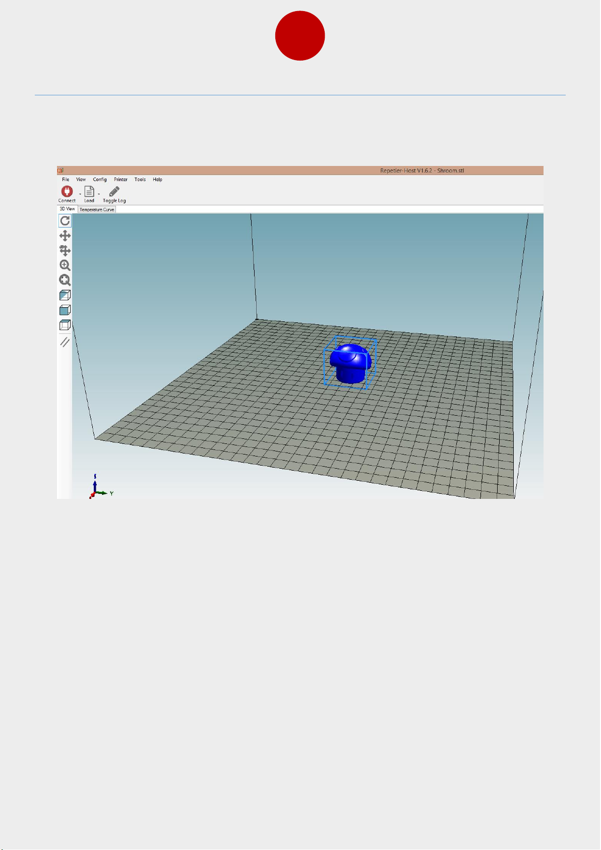
After this you are set and you can drag and drop a STL model from the folder to RepetierHost screen. After this you can click “Slicer” tab again and click “Slice with CuraEngine”
Now on left side of screen you can see “Connect” button. Press it to make the connection
between printer and PC. If everything is ok, you can now press the print button and wait for
your first print to start.
Page 54

Page 55

Page 56

 Loading...