

Tevion DR2501 Instruction Manual
MODEL: DR2501
DVD HOME THEATRE
INSTRUCTION MANUAL

Important Safety Instructions
When using any electrical apparatus always observe safety regulations and use basic
safety precautions to reduce the risk of fire, electric shock and personal injury, including
the following.
1.Read, Keep and Follow these instructions, heeding all Warnings.
2.Keep out of reach of young children. This apparatus is not suitable for use by young children or infirm persons
without supervision. Young children must be supervised to ensure that they do not play with the apparatus.
3.WARNING. Do not insert any objects into any openings of an electrical apparatus.
4.WARNING. Do not touch any moving parts of any electrical apparatus.
5.WARNING. Do not use this apparatus near water. To avoid the risk of fire or electric shock, do not expose this
apparatus to rain or moisture. The apparatus is not to be exposed to dripping or splashes.
6.WARNING. Objects filled with liquid, such as vases, are not to be placed on any electrical apparatus.
7.Do not immerse in any liquid whilst in use or during cleaning. Clean only with a damp cloth, dry with a dry towel.
Do not use harsh abrasives as these may damage plastic parts.
8.DO NOT block any ventilation openings. Install in accordance with the manufacturer's instructions. Always
allow a sufficient gap around the apparatus to avoid overheating.
9.DO NOT install near any heat sources such as radiators, gas heaters, stoves or other apparatus (including
amplifiers) that produce heat. Do not leave in direct sunlight.
10.WARNING. Do not place any naked flame source, such as lighted candles on any electrical apparatus.
11.Connect to a suitable 230-240 ~ 50 Hz power supply only.
12.Always unplug from the power source when any electrical apparatus is not in use.
13.Do not abuse or damage a power cord. If any power cord is damaged, it must be replaced by the manufacturer,
its service agent or a similarly qualified person in order to avoid a hazard. A replaceable cord must be replaced
with an authorised replacement from an authorised service agent only.
14.Only use attachments/accessories specified by the manufacturer.
15.Unplug this apparatus during lightning storms or when unused for long periods of time.
16.Attention is drawn to the environmental aspects of disposing of any battery.
17.Refer all servicing to qualified personnel. Servicing is required when the apparatus has been damaged in any
way. This includes damage to the power supply cord or plug.
18.Do not attempt to service any double insulated apparatus. Double insulated apparatus requires specialist
servicing and knowledge to retain the safety of the apparatus.
19.WARNING. Do not use any electrical apparatus outdoors. If any electrical apparatus is to be used outdoors,
use a suitable Isolating transformer or Electrical Safety Switch (RCD).
20.For household use only. This apparatus is not intended for commercial use.
21.If this apparatus is to be used by a third party, please supply these instructions with it.
22.No liability will be accepted for any personal injury or damage caused by failure to follow these instructions.

SAFETY INSTRUCTIONS
W A
WARNING
The exclamation mark within a triangle is a warning sign alerting
the user to important instructions accompanying the product.
The lightning flash with arrowhead symbol within a triangle is a
wa rn in g s ig n ale rt in g t he u ser t o da ng erous v oltage
unit.
To reduce the risk of electric shocks, do not remove the cover. No
user-serviceable parts ins ide the u n it. Refer all s e r v ic
qualified personnel.
This unit uses a laser. Onl y a qua lified service person should
remove the cover or attempt to service the player due to possible
eye injury.
Invi s i ble las e r radiation may occur when the unit is opened or
interlocks are by-passed. Avoid exposure to laser beam. Use of
c on trols, a dj u st me nt s or proc ed ures o t he r th an t h os e sp ec if ied
he re in ma y res ult i n haz ardou s rad ia tion ex pos ure.
i nside t he
in g
NOTE
This produ ct incorporates copy right pr otec tion
techno logy that is protected by method claims
o f U . S . pa t en t numbers 4,631,603; 4,577,216;
4 , 81 9 , 098 a nd 4 , 9 07 , 09 3 , a nd oth er
in t ell e c tua l p r ope rt y ri gh ts owned by
M a c rov i s i on Corpo ration and other righ ts
to
ow ne rs. Use o f t h i s c op y ri g h t protection
technology must be au tho ri s ed b y Macrovision
Corpo ration , and is intended for home and
othe r li mited v i e w i n g us es on ly , un less
othe r w ise au t ho ri s ed b y Mac rovis ion
Cor p o rati o n . R e v e r s e en g i nee ri n g or
disassembly i s prohibited.
230- 240V
This unit operates on
a long time, th e AC pow er cord sho uld be un pluge d.
The unit must not be e xpose d to moisture or ra in.
The unit should not be exposed to dripping or splashing and objects
containing liquids, such as vases, should never be placed on top of
it.
The power switch for the unit is mounted on a secondary circuit
and does not disconnect the whole unit from the mains in OFF
position.
Plea se en sure that all connections are properly made before
operateing the unit.
The unit shou ld be positioned so that it is properly ventilated.
Avoid p lac
inside a built-in fixture such as a bookcase.
Openings for ventilation must not be blocked or covered during
use.
Do not expose this unit to direct sunlight or heat sources.
in g
230
it,
for example, close to curtains, on a carpet or
V~50 Hz. I f it is not to be used for
-240
Manufactured under li cenc e from Dolby
Laboratories. Dol by and the double-D
" "
symbol are trademarks of Dolby Labora tori es.
C
1992-1997
Confidential Unpublished works.
Dolby Laboratories, I nc . All rights reserved.
CAUTION
Use of controls or adjustments or performance
of procedu res other than those specifie d herein
ma y r es ult in hazardou s radiation expo sure.
Do not open covers and do not repair yourself.
Refer serviceing to qualified pers onnel.
This DVD V IDEO player is class ified as a
CLASS 1 LA SER PRO DUC T as stated on the
back of the set.
CAUTION:
1. Do not operate the system in an enclosed cabinet and allow about 10cm(4 inches) of free space all around the receiver for
adequate ventilation.
2. No naked flame sources, such as lighted candles, should be placed on the apparatus.
3. Attention should be drawn to the environmental aspects of battery disposal.
4. Apparatus shall not to be exposed to dripping or splashing and no objects filled with liquids, such as vases, shall be placed on
the apparatus.
This symbol is known as the Crossed-out Wheelie Bin Symbol . When this symbol is marked on a product, it means
that the product should not be disposed of with your general house hold waste. Only discard electrical/electronic
items in separ ate colle cti on s ch e mes which cater for the recovery and recycling of the materials contained within.
Your co-operation is vital to ensure the success of these schemes and for the protection of the environment.
1

INTRODUCTION
Thank you for purchaseing this DVD H o m e Theatre Sys tem. This Home Theatre sys tem i n c l udes everything you need to
experience movie theatre quality d i g it a l v ideo and au dio plus AM /F M r ad i o r e c e p ti on i n the c o mfo r t o f y ou r o w n home. The only
thing you need t o ad d is y ou r o w n T V . W e ha v e de s igned t h is sy s te m t o be ea sy t o s e t up , bu t p lea s e , r e v i e w t h i s m anua l be fo re
y ou ope ra te y ou r sys te m. P l ea s e ha v e i t hand y w h il e y ou a re s e tt i ng t he sys te m up ; and k e e p it a v a il ab le f o r f u t u re re f e ren c e , or
in the unlikely ev ent th at you encounter any unexpected questions or problems. We have tried to keep this manu al a s s imp le as
poss ibl e. It beg in s w it h ho w t o c onne c t t he s p e a k e rs , y ou r T V , a n d o t he r op ti ona l d e v i c e s . It a l s o i n c l ude s i n s tr u c ti on s on ho w to
position t he s p eakers for the most natural s u rr ou nd sound , and fi nally how to o perate the DV D/CD player. If y o u f o llo w t he
instructions care fully y ou c an have the system set up and start playing in l ess than an ho ur.
DVD play er s (and discs) have many features which are not available on any other movie playback medium (such as VHS or even
original films themselves).
In addition to the software on a disc being physically much smaller and easier to store than the older VHS format, the life span of a DVD
disc is much longer than a VHS tape and able to retain the movie for many more years. Additionally, the main point of DVD s is to allow
you to view the movies in your own customised way. The options are almost limitless for customised viewing from languages to angles
to scenes to speeds to sounds and track mixes, etc.
This sys tem w as designed to provide you with many years o f r e li ab le ope ra ti o n w it h a m i n im u m o f c a re and ma in tenan c e .
I f y ou e x p e ri en c e an y p rob le m w it h t he s e t up o r o p e ra ti on o f t h is system, please review the Trouble Shooting Guide at the end of
this manual.
A ll o f t he op ti ona l a d ju s tab le sys te m s e tti ng s ha v e been p re -s et a t ou r f a c t o ry f o r c o rr e c t ope ra ti on o f t he s ys te m. A ll y ou ha v e to
d o i s to in s e rt a d i sc , s i t b a ck , and en j o y a g r ea t ho m e theatre e x pe r ien c e.
Even tually you may want to change some of the optional s e ttings like speaker balance or equaliser settings. A d escription of all
the optional s etting s, an d i n s tr u c t io n s f o r c h a ng in g th e m, a r e f ou n d l a te r i n t h is ma nu a l.
,
Features & Benefits of DVD movies and players:
1 .Sharper, clear pictures with greatly enha n ced d igital sou nd.
Yo u w il l imm e d ia te l y no t ic e t he im p ro v e men t o v e r t he o l der
VHS Movie form at.
2. Dolby Dig it al
T hi s DV D pl a ye r (a nd mo st d is cs ) i s Do lb y D ig it al c o mp at ib le,
w hich allo w s very s ha rp an d c ris p sou nd r e produ cti on i n y our
ho me, esp ecially us efu l, i s t he s urroun d so und fe ature.
Multi-language compatible
3.
Setup and subtitles can be displayed in many different
languages.
Parental Controls
4.
Parents can lock ou t movies (by ratings) f rom being viewed by
childre n ev en i f th e pa rents are no t at hom e.
Freeze frame and frame by frame play
5.
Th is i s v ery usef ul for spo rtin g e vents. Also slo w m otio n p lay is
po ssib le w ith thi s se t.
Zoom feature
6.
Al lo ws y ou t o zo om i nt o a sc en e an d st il l ma in ta in r ea so na ble
pictu re clarity (de pe nding on the d isc ).
Time Search
7.
This DV D pla yer c an locate an e xact scen e with a time search,
for example , you can go to a sc ene wh ich is 15 minu tes an d 12
se cond s in to t he m ovie directly.
Director s Cuts
8.
View special director s cuts and comments on some discs. Many
of these discs give a narration of what the director was thinking
about when he or she was filming a scene, as well as the scene
itsell.
,
,
9 . Scene Repeat
You can easily program your player to see a scene over and
ov er a gain witho ut d ama g in g the m ov ie me di a.
10. Fast Play
This DVD Player can p lay at very high speed s (backwards
or forwards ). T hi s is v ery u se fu l f or q uickly l o c a t i ng
your favourite scenes.
11 . MP3 comp atibili ty
This DVD Player can also play MP3 encoded discs (most
formats are supported).
12. A
ud io CD compatibility
This DVD Playe r can also play audio (music) CDs thereby
sa ving the exp ens e of buying a separate CD player.
13. VCD fo rm at
S o m e sto re s ma y c a rry VC D fo rma t
sharp or versatile as DVD discs movies. This set can play
VCD disc movies.
14. Regi on al Codes
This prevents discs designed for use only in some countries
from be ing played in other countries. The DVD Forum assigned
region numbers for different coun tries. Australia is R eg ion
(this set can only play Region 4 DVD movies).
15. JPEG Compatibility
Th is DVD H OME THEATRE s ys te m a ls o a l lo w s y ou to
view
16. DivX
This DVD HOME THEATRE system also allows you to view DivX
discs.
4
JPE G fil es or pict ure C Ds.
x Compatibility
discs, which are not as
4
2

TABLE OF CONTENTS
G ett ing Started:
Safety Instructions-------------------------------------------------------1
Introduction------------------------------------------------------------------2
Connections:
Choose Your Connection----------------------------------------4
Cables Needed to Connect Components
to Your TV -----------------------------------------------------------4
Speaker System Connections------------------------------5,6
Speaker Positioning Information---------------------------7,8
TV Connection - with Video Cable Connection----------9
TV Connection - with S-Video Cable Connection------10
TV Connection - with COMPONENT -----------------11
AM/F M Antennas -------------------------------------------------12
TV + VCR Connections ----------------------------------------13
TV / VCR Combination Connections-----------------------14
TV + VCR + Satellite Receiver Connections-----------15
AUX IN (AUX 1 / AUX 2) Connections -------------------16
Location of Controls ----------------------------------------------17,18
Remote Control Operation --- ------------------------------------- 19
Index to Parts and Controls (Front Panel Display)--------- 20
Notes on Discs ----------------------------------------------------- 21
Precautions---------------------------------------------------------------- 22
Settings & Adjustments:
General Setup ---------------------------------------------------------- 23
Setting the Video Output ------------------------------------------ 24
Setting the TV Display ----------------------------------------------- 25
Setting On Screen Display Language ----------------------- 26
Speaker Setup ----------------------------------------------------- 27
Audio Setup -------------------------------------------------------- 28
Preference Setup:
Getting Your System into the Stop Mode ----------------- 29
Setting Audio, Subtitle, Disc Menu Language --------------- 29
Setting PARENTAL ratings ------------------------------------- 30
Setting PASSWORD --------------------------------------------- 31
Returning to the Original Factory Default Settings ------ 31
-
Playing Discs:
Basic Playback 1 -------------------------------------------------- 32
Basic Playback 2 -------------------------------------------------- 33
Speaker Volume -------------------------------------------------- 34
Special Functions:
Search & Skip Functions ---------------------------------------- 35
Pause Function and Step Play -------------------------------- 35
Repeat Play --------------------------------------------------------- 36
Programmed Play ------------------------------------------------- 37
Playing a Specific Track or Chapter ------------------------- 37
Zoom Play ---------------------------------------------------------- 38
Slow-Motion Play -------------------------------------------------- 38
Viewing from a Desired Angle --------------------------------- 39
Audio Language Selection ------------------------------------ 39
Subtitle (Caption) Language Selection ---------------------- 40
Selecting the Sound Equaliser -------------------------------- 40
Using the Sleep Timer ------------------------------------------- 40
Other Functions:
DivX, Mp3 disc operation ------------------------------------------- 41
Playing Video CDs with PBC ----------------------------------- 42
Adjusting the Audio Mode -------------------------------------- 43
Displaying DISC Information ----------------------------------- 44
Viewing JPEG Files or Picture CDs -------------------------- 45
AM/FM Radio ------------------------------------------------------ 46
Troubleshooting 47,48,49,50
Glossary 51
---------------------------------------------
Specification 52
-----------------------
--------------------------------------------------------------
3
CONNECTIONS
Choose Your Connection
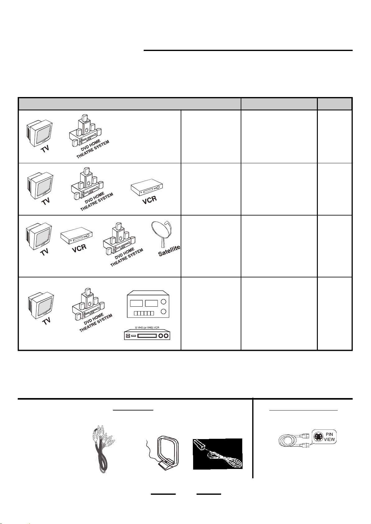
There a re several ways to con nect y o u r DVD Home Theatre System. Please use the following cha rt to determine which
conne ction is the best for you . Turn to t he appropria te p age and c onn e c t you r DVD Home System.
Theatre
COMPONENTS
STEREO TAPE DECK
TV
+
DV D HO ME THEATRE
SYSTEM
TV
+
D V D H OME THEATRE
SYSTEM
+
VCR
TV
+
DV D HO ME THEATRE
SYSTEM
+
VCR
+
Satellite
DV D HO ME THEATRE
SYSTEM
+
TV
or
S-VHS (or VHS) VCR
or
STEREO TAPE DECK
CABLES NEEDED
Video (included)
Aud io (optiona l, inc luded)
S-Video (op ti onal, not
inc lu ded)
Video (i nc luded)
Aud i o (op ti ona l, in c luded)
S-Video (op ti ona l, not
inc l u ded)
Video (inc luded)
Aud io (optiona l, included)
S-Video (op ti ona l, not
inc luded)
Video (inc luded)
Aud io (optiona l, included)
S-Video (op ti ona l, not
inc luded)
GO TO...
Page
9,10,11
Page
13,14
Page 15
Page 16
Cables Needed to Connect Components to Your TV
The pictures below show the cables needed for the connections represented in this booklet.
NOTE: Audio cables are usually sold as a bundled set, but the connection sketches in this booklet show each cable separately for better
visibility. Audio c ables are on ly needed if you want to connect your VCR audio or tape player to the DVD HOME THEATRE
SYSTEM. Most people will only need a TV set with a video input jack and no extra cables.
INCLUDED
RCA cables
A M an t enna
FM an t e nna
4
N
O
T
INCLUDED
S-Video cable
(n ot includ ed)
SPEAKER SYSTEM CONNECTIONS
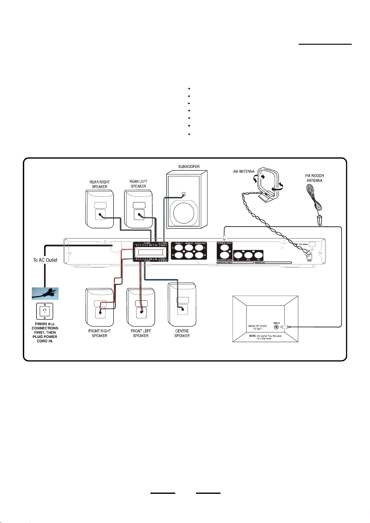
Speaker System Connections
Connect the supplied speaker system by matching the colours
of the terminals to those of the cords.
IMPORTANT:
Before making connections, ma ke sure the power is off.
The speaker wires and connectors are colour-coded for easier set
up.
Conne ct t he Front Left speaker to the L terminals.
Connect the Front Right speaker to the R terminals.
Connect the Centre speaker to the C terminals.
Connect the Surround Left speaker to the SL terminals.
Connect the Surround Right speaker to the SR terminals.
Connect the Subwoofer to the SUB terminals.
Insert the video cab le i nt o th e VI DE O OU T ja ck o n th e
back of your DVD H OM E TH EATRE SYSTEM. and into
the VIDEO IN jack on you TV.
NOTE
1 Video cable is included for connecting to your TV set s Video input jack
and Blue) use this connection for better picture quality. The Component Cables Red , Green and Blue )are not included.
)
,
. If your TV set has Component Video Inputs( Red,Green
(
)
5
(
SPEAKER SYSTEM CONNECTIONS
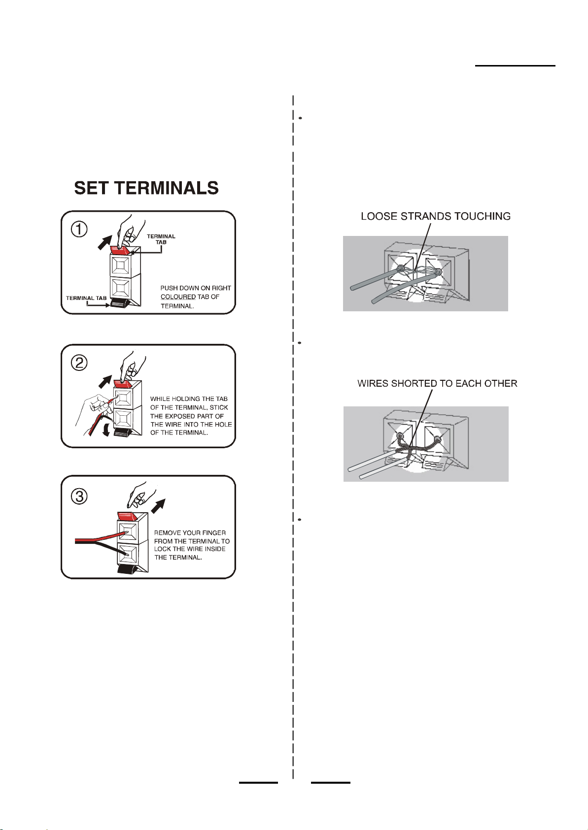
Tips for connecting the speaker wires
Unw ind and stretch out the speaker wires at tach ed wi th e ach
spea ke rs , then pu sh and hold down the set termina l tab on the
back of the main set to insert each wire. Make sure the wire is fully
inserted, but the insulation is not covering the inserted part of the
speaker wires.
To avoid short-circuiting the speakers
Ma ke s ure the strippe d end of each s pea ker wir e do e s not
tou c h an o the r spea ker term ina l or the stri p p ed end of
another speaker wire.
Examples of poor connection of the
speaker wires
Stripped spe aker wire is to uc hi ng ano t h er set t ermi nal.
Make sure not even 1 strand of wire touches the other wire!
NOTE:
Be sure to match the speaker wire to the appropriate terminal on
the back of the main set: (+) to (+) (colour), and (-) to (-) (black). If the
wires are reversed, the sound will be distorted and will lack some
tones. Follow the colour codes of each terminals.
S tripped wire s are touching ea c h ot he r du e to exc essive
removal of i ns ulati on. Do not allow the ab ove to hap pen on
you r s e t.
NOTE: If longer wires are n eeded , you may bu y a ny go od qu ality
speaker wire and sp lice the wires yourself. Please make sure
the wires are not shorting to each other and observe the correct
co lou r p olarity. M an y sp eak er w ires h ave a dotted line or solid line
or raised rib on on e side to identify each side.
Also make sure you use electrical tape to co ver your splices.
6
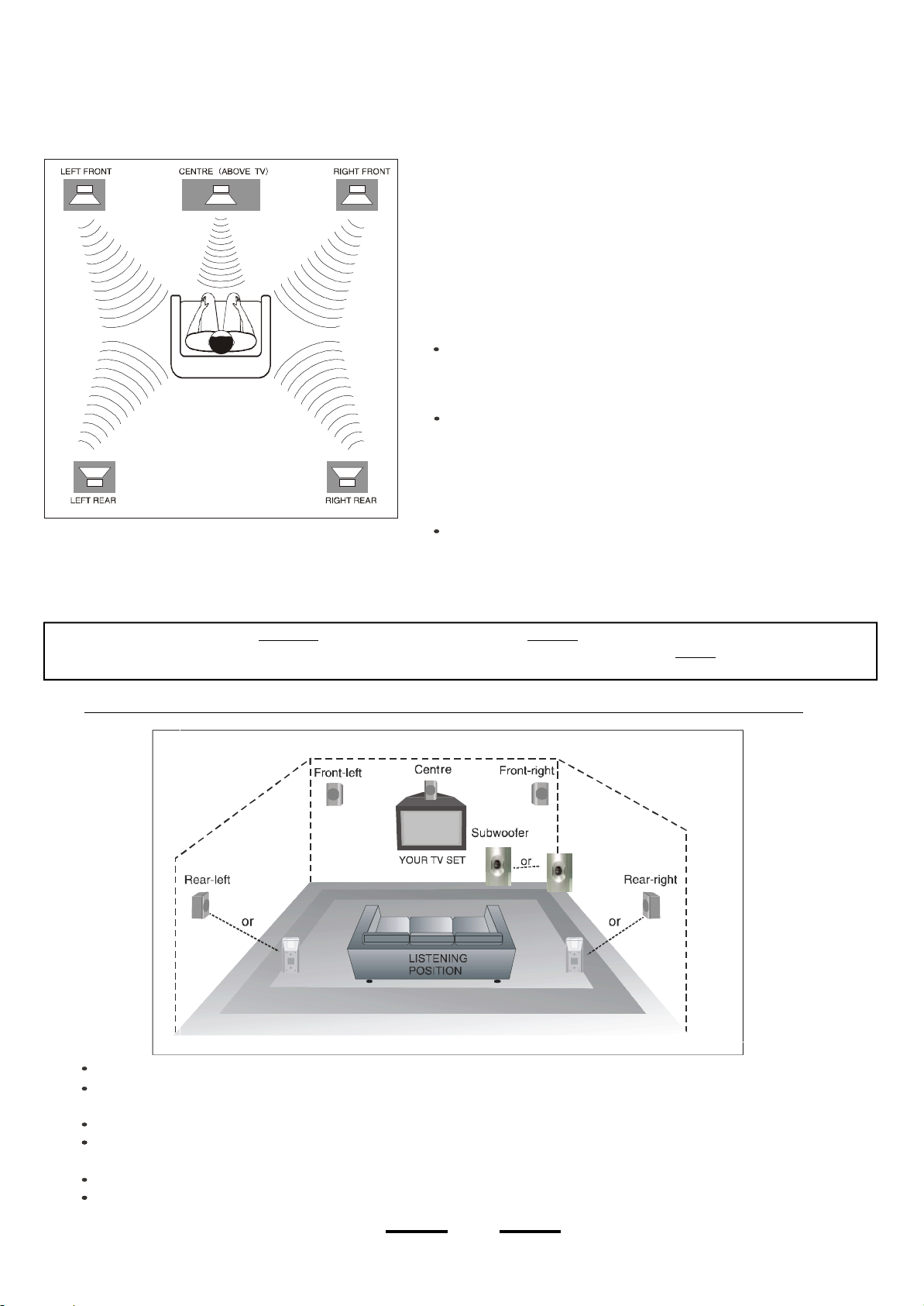
SPEAKER POSITIONING INFORMATION
Your system is supplied with 5 compac t si zed s ate llit e s pea k er s and
one large sub woo fer. The satellite spea kers reproduce only the midrange and higher fr equen cies. All o f t he lo w f requency (ba ss ) s ounds
a re p ro d u c ed b y th e s u b w o o f e r . Proper po sit ioning an d placement
of t he s pe akers is imp ort ant in o r d e r to pro vide the best surround
soun d experience. We understand that due to the size and shape of
your l istening room, a nd the loc ation of your furniture, you m ay not
be able to set up the speakers exactly as pe r these diagrams. However
the se simp le guidelines will help you maximise your home theatre
experience.
Your Usual Se at
POSITION ALL 5 SPEAKERS APPROX IMATELY AT THE
SAME DISTANCE FROM YOUR LISTENING POSITION.
POSITION THE SUBWOOFER AS BELOW.
NOTE : You may only place the CENTRE spe aker (blue terminals) or the FRO NT spe akers (red t erminals) on or near your TV
set or computer monitor. The se speakers have magne tic shielding inside. If you put the REAR speakers near your TV
s e t o r c o m pu te r m o n it o r, t he c o lou rs o n y o u r T V o r c o m pu t e r m on it o r m a y c han g e.
Note the speaker levels are pre-set at the factory and most people will
not need to fine tune the sound of each speaker. We suggest you skip
this part at fir st. Later on you can fine tune the sound le vel of each
sp ea ke r. S e e P a g e 3 4.
Although all 5 satellites are of the same size, the speakers inside the
cabinets are different. The speaker wires on the back of the cabinets
are colour-coded, as are the speaker terminals on the back of the main
unit. Refer to the connection diagram on page 5.
Be sure you are u si ng the corr ec t satellite s peaker in eac h lo cation,
front, rear a nd center. Pl ea se follow t he c olours for be st results.
This is espec ially impor ta nt for the ce nt er speaker.
For best surround sound ef fects, all 5 of the satellite speakers should
be roughly at the same distance from your usual listening position.
POSITION THE SPEAKERS LIKE THIS FOR OPTIMAL LISTENNING EXPERIENCE
All 5 satellite speakers should be placed approximately the same distance from your listening position.
The cen tre spea ker shou ld be placed directly abo ve (or be low) the TV set. Le ft and righ t fron t spea kers shou ld be app roximately
at the same height as the centre speaker.
The rear speakers should be either in line with, or behind your listening position, approximately at ear level, or slightly above.
The subwoofer should be on the floor near the TV, or in any corner, b ut reme mbe r you need a clear path to your remote (Don t
block this set with a curtain).
All speakers must be visible. Do not hide them behind curtains, furniture, etc, as this will affect the sound.
You may only place the centre speaker (blue wires) or front speaker (red wires) near or above the TV set because these
speakers are magnetically shielded.
,
7
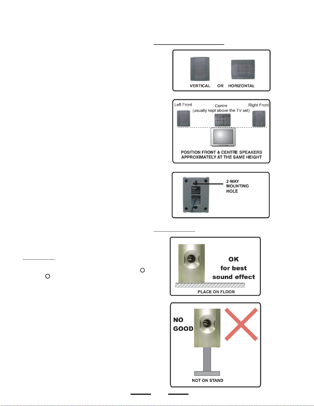
SPEAKER POSITIONING INFORMATION
S
ATELLITE SPEAKERS
· The centre speaker, as well as the other 4 satellites, can be
positioned either vertically or horizontally.
· The left front, right front, and centre speakers should be
placed at roughly the same height. The centre speaker
reproduces most of the dialogue spoken by the actors on
the TV screen, therefore it should be placed either directly
above or below the centre of the TV set. Once you position
the centre speaker, try to position the left front and right front
speakers at the same height. It is not recommended to place
any of the satellite speakers on the floor. Many people prefer
to place the centre speaker horizontally above the TV set.
· The left rear and right rear speakers can be placed in line
with your listening position or behind your listening position.
Ideally they should be placed slightly above your ear level
when you are seated in your normal listening position.
· We have provided 2-way keyhole openings on the back of
all the satellite speakers that allow the satellite speakers to
be wall mounted in either a vertical or horizontal position.
· The subwoofer will provide the most dramatic bass effects
(low frequency sounds) when it is placed on the floor. Do
not place the subwoofer on a stand or table. The subwoofer
should be placed in the front of the room so that it is facing
toward your listening position. It can be placed on either
side of the TV or even in the corner of the room, as far away
as the cable will allow. The bass sounds from the subwoofer
are non-directional. You will not really be able to tell where
the bass is coming from.
SUBWOOFER
· LONG ROOMS - In case your room is unusually long, you
may buy speaker wires from your dealer for adding wire
length to your speakers. Be careful not to allow the plus +
and minus - wires to touch each other. Use electrical tape
or plastic connectors to insulate the wires.
8
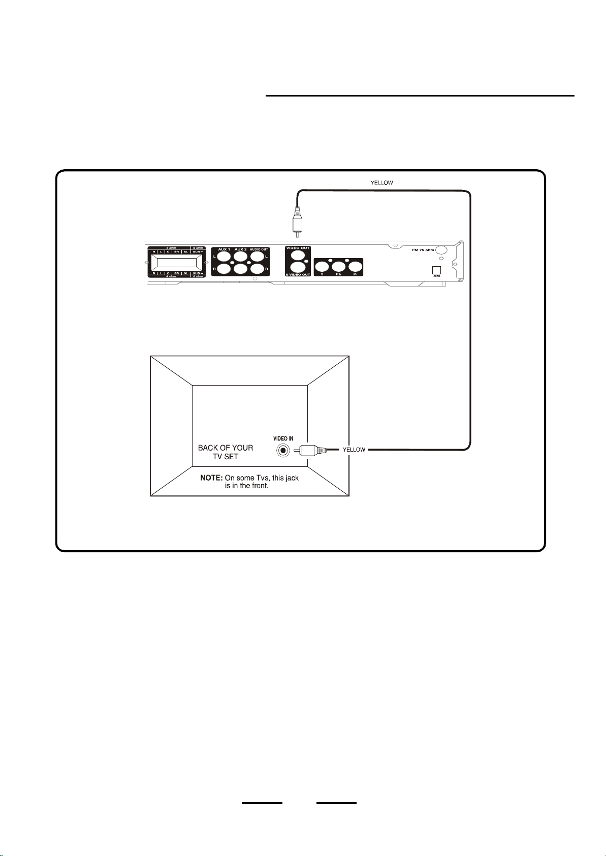
TV CONNECTION
with Video Cable Connection
DVD Home Theatre System+TV with a Video Input Jack
NOTE: Your TV set must have a VIDEO INPUT connector (or COMPONENT connector) for you to be able to connect and enjoy this
DVD HOME THEATRE SYSTEM.
h
CON NEC T ALL SPE AKE RS AS SHO WN ON PAGE 5
YEL LOW VIDEO CABLE
(INCLU DED)
Use this if your TV has
no component jack and no
S-Video jack
IF YO UR TV HAS NO COMPONENT JACK BUT
HAS AN S-VIDE O JACK, SEE PAGE 10
FOR INS TURCTIO NS ON CONNE CTIN G THIS
1. Connect the 5 satellite speakers and subwoofer as shown on P age 5
2. I n s e rt t he v i deo c ab l e (y e ll o w ) i n t o t h e V I D EO O U T j a c k on t he b a ck o f y o u r DVD HOME THEATRE SY S T EM , and
i n t o t he V I D EO I N j a ck on y o u r T V . T h i s c o n ne c ti o n w i ll a ll o w y ou t o e n j o y v i de o i m age s o f no r m a l q u a li t y.
3. Insert the AC power cord into an AC socket, the STANDBY indicator will turn on in red automatically.
4. Pre ss the ON /STANDBY bu tton on th e main set or on the remote control to turn on t he set, and the STANDBY
indicator will be off.
5. Select yo ur TV s video chan nel (see the NOTE on pa ge 23 ).
6. Go to Page 32 for playing DVDs (discs ).
ANTENNAS:
1. Your cable or antenna connection to the television should not be affected by this connection. Connect your antenna cable
to your television as you normally would. You may need to consult your television manual for details, but no changes will
be made to your current antenna connections.
For the home theatre antenna connections, we supply an AM loop antenna. Connect this to the AM terminals.
2..
3.
For the FM antenna, you may use the indoor wire antenna we supplied or you may use an antenna spliter & cable to
connect an outdoor antenna to the FM antenna on the back of your set. Better FM reception will probably be received
with an outdoor FM antenna.
, ,
.
9
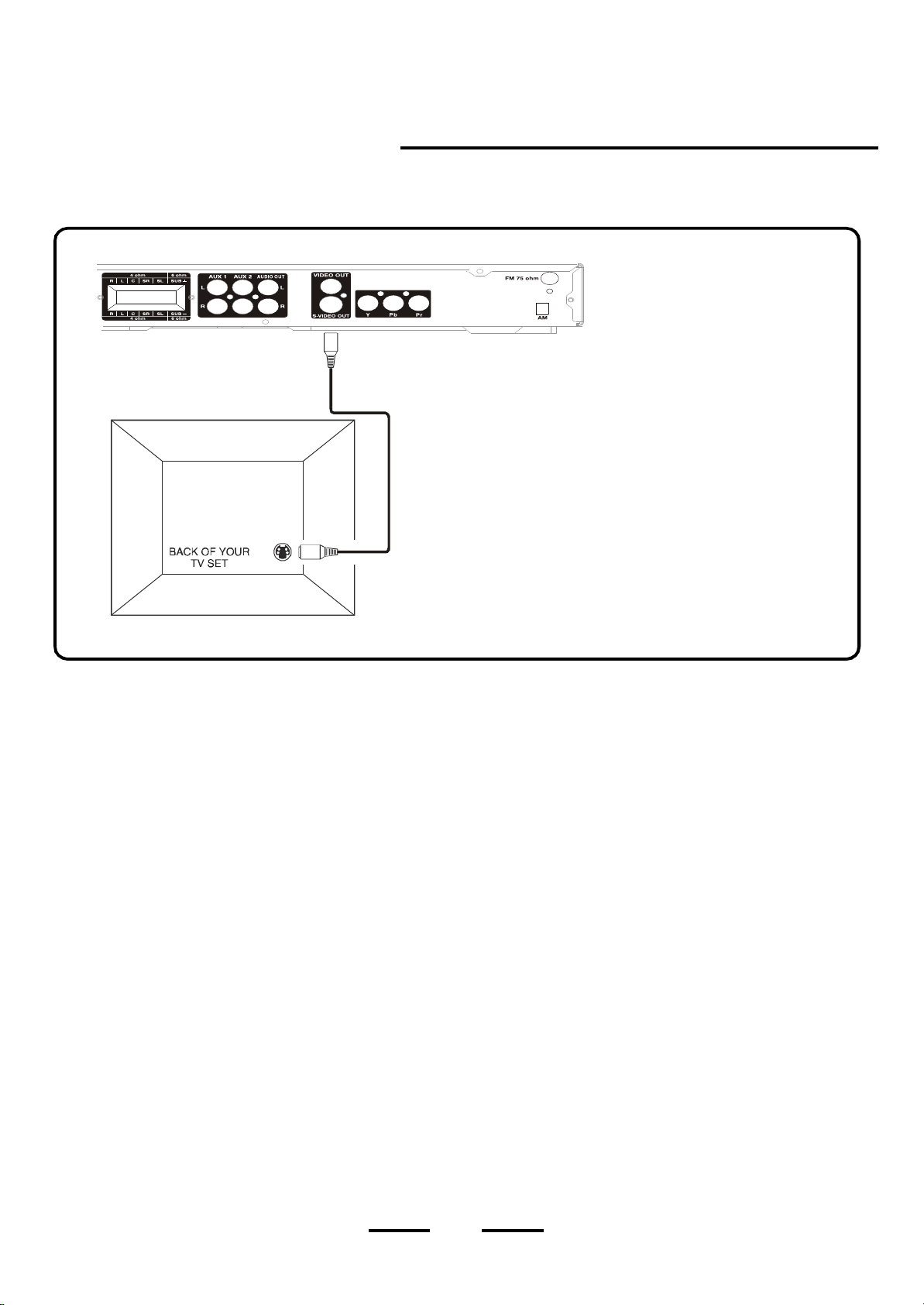
TV CONNECTION
with S-Video Cable Connection
DVD Home Theatre System + TV with an S-Video Jack
CONNECT ALL SPEAKERS AS SHOWN ON PAGE 5.
h
NOTE: On some TVs, this jack
is in the front.
h
S-Video cable (not included) provides a sharper
picture than normal video. Use an S-Video
cable if your TV has an S-Video jack (but not
component jack).
N OTE : Yellow Video plug and wire are not used
when using S-Video or component. If your
TV has no COMPONENT or S-Video jack,
use the VIDEO IN jack and cable as shown
on page 9.
1. Connect the 5 satell ite s pea ke rs and subwoofer as shown on P age 5.
2. In s e r t t he S -V ideo c ab l e i n to th e S -V IDE O OU T j a c k on t he b a ck o f y o u r DVD H O ME THEATRE SYS T EM a nd to
the S-VIDEO jack on your T V. Thi s c onn ecti on will allow you to enjoy higher quality imag es. If your TV Doesn t
have S- VIDEO , use the ba sic video conne cti on listed on Page 9 ( y e ll o w plug s: VIDEO IN or OUT are not
needed for S -V i de o
3. In sert the AC p o w e r cord into an AC s ock et, t h e STANDBY indicator will turn on in red automatically.
4. Press the O N/STANDBY button on the main s et or on the remote control to turn on the set, and the S TANDBY
indicator will be off.
5. Se lect yo ur TV s video channel (see the NOTE on pa ge 23).
6. Go to Page 32 for playing DVDs (discs).
ANTENNAS:
1. You r cable or anten na connection to the television sho uld not be affected by this connection. Conne ct your
antenna cable to your televi sion as you norma lly would. You may need to consul t your television manual for
details, bu t no changes will be made to your current antenna connections.
For the home theatre antenna connections, we supply an AM loop antenna. Connect this to the AM terminals.
2..
3.
For the FM antenna, you may use the indoor wire antenna we supplied or you may use an antenna spliter & cable to
connect an outdoor antenna to the FM antenna on the back of your set. Better FM reception will probably be received
with an outdoor FM antenna.
).
,
,
10
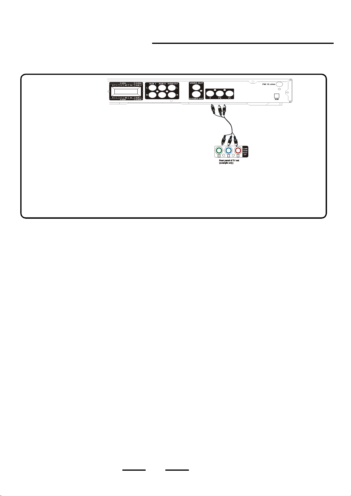
TV CONNECTION
with YPbPr Cable Connection
DVD Home Theatre System + TV with a Component Video Input Jack
NOTE 1: Wh en us in g the component c ab le , n o yel lo w vid eo ca bl e
NOTE 2: For the be s t picture possible, use the
h
is needed . For best resu lts, remove t he cables not needed.
on your TV, and set t he VIDEO ou tpu t to If
your TV doe sn t have a , b ut ha s a V IDEO
or S-VIDEO jack, you must use the normal vide o c able
or S-v ideo cable and set the VIDEO output to S-VIDEO
for S- VIDEO connection.
,
component jack,
h
component
component.
j a ck
COMPONENT CABLE
(NOT INCLUDED)
Pb Pr
1. C o nne c t t h e 5 s a t e ll i te s pea k e rs and s u b w oo f e r as shown on Page 5.
2. The component jack of the unit and the TV set are colour-coded for easy connection. Insert the three coloured ends of the
COMPONENT cable not supplied ) into the same coloured COMPONENT output jjacks on the back of your DVD HOME
THEATRE SYSTEM, and the other ends of these cables into the corresponding coloured component input jacks on your
TV set. Please make sure the colours are matched correctly.
3. In s e r t t he A C p o w e r c o rd i n t o a n A C s o c k e t, th e S TAN D B Y ind i c a t o r w illl t u rn on in re d a u to ma ti c a ll y.
4. P re s s t h e ON /S TA ND BY bu tt on o n th e m ai n se t or on t he r em o te c on tr ol to t ur n on t h e se t, a n d t h e S TA N D BY
in di ca tor w i l l b e o f f.
5. S e le c t y o u r TV s vid eo c ha n ne l ( s e e t he N OT E on pa g e 2 3 ).
6. G o t o P a g e 3 2 fo r p l a y i ng DVD s ( d isc s ).
ANTENNAS : 1 . You r cab le o r an tenna conne ction to the televisio n shou ld not be affected b y this connection. Connect
your antenna cable to your television as you normall y wou ld . You may need to consult your television
manual for deta ils , but no changes will be made t o your curr ent a n tenna connections.
2. Fo r t h e ho me theatre a n ten n a c o nne c t ion s , we supp ly an AM loop a ntenna. Connect th is to the AM
terminals.
3. Fo r the FM antenna, you m ay us e t he indoor wire ante nna w e s upp lied or you may use an antenna
splitter & ca ble to connect an outdoor antenna to the FM antenna terminal on the back of your set.
Better FM reception will proba bly be received with an outdoor FM antenna.
( )
,
j
j
11
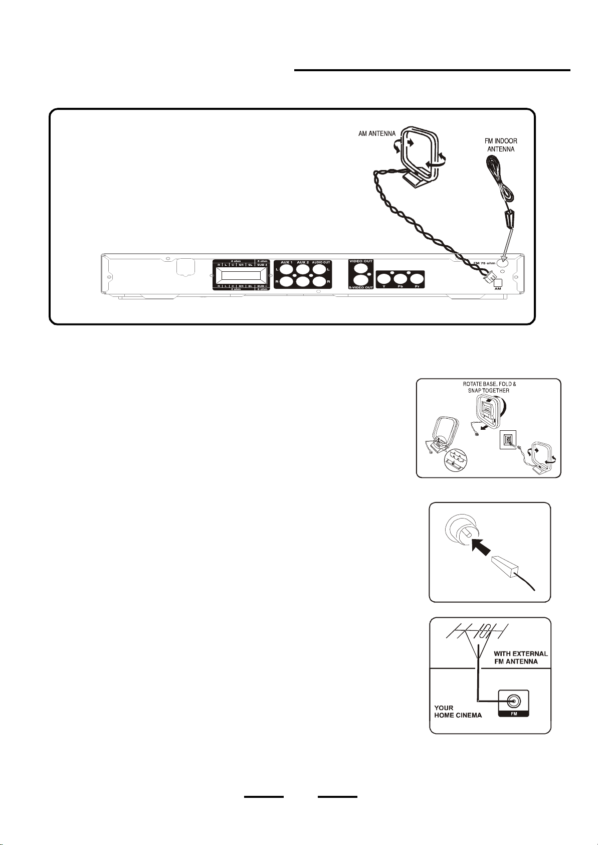
AM / FM ANTENNAS
IMPORTANT!
· Before conne cting the AC power cord to the wall out let, e nsu re that all other co nnections have been made.
· Never make or change any connections with the power switched on.
· The type plate is located at the rear of the system.
Connecting antennas
AM Indoor Loop Antenna
Connect the s upplied AM loop antenna to the A M antenna terminals. Position the loop
antenna to receive the clearest sound. The base of the AM antenna folds up to form a small
platform for this loop antenna.
FM Indoo r A n t enna
Connect the supp lied FM antenna wire to the F M terminal. J ust insert the plastic piece of the
FM indoor antenna into the FM connector. Move the antenna in various directions until the
clearest signal is received.
N ote: Ke ep th is FM an te nna a s far a w ay as poss ible from the TV, VCR or any radiation
source to prevent possible unwanted noise.
FM Ou t doo r A ntenna
For better FM reception, use a 75 ohm coaxial cable (not supplied) to connect the sys tem
to an o utdoor FM antenn a as sho wn.
Insert your an tenna s connector into the FM antenna conne ctor on the back of the set.
You may need a signal splitter and extra cable if your outdoor antenna is already connected
to your TV or VCR.
· After connecting the antennas, please
NOTE: s ee p age 4 6 to play the AM/FM rad io.
INSER T THE FM
INDOOR ANTENNA
12
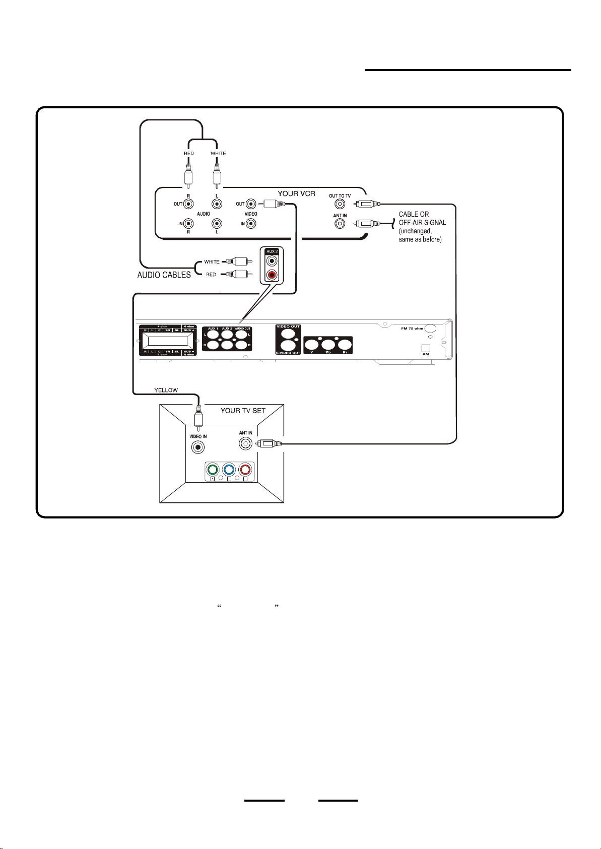
TV + VCR CONNECTIONS
Extra Video Cable (not included)
Component YUV
Pb Pr
1 . C o nne c t t h e 5 s a t e ll i te s pea k e rs and s u b w oo f e r as shown on Page 5
2. Insert the s te reo audio cables (included) into the HOME THEATRE A UX 1 o r AU X 2 A UD IO I NP UT L ( L e ft = W h i te ) a nd
R (Right=Red) jacks and into the co rresp onding AUDIO OUT jacks on your VCR, this will allow your VCRs sound to
play through your HOME THEATRE SY STE M.
NOTE : Your VCR s te reo sou nd will com e out of 5 spea kers plus subwoofer s ince the f ctory s default
setting for the sound output is PRO LOGIC . Press the SURROUND button if you want to return to STEREO
(2 c hannel) sound output, and the sound will on ly come out of 2 speakers plus subwoofer (probably best for
VCR soun d).
3. Insert the video cable (y ellow) into th e VIDEO OUT jack on the back of you r VCR player, and into the VIDEO IN
ja ck on y o u r T V .
4 . u s ing a co ax ial an te nn a c ab le.
Connect your VCR with your TV
5. Connections of your other antenna cables are not changed when you add your DVD HOME THEATRE SY ST EM.
6. Insert the AC power cord into an AC s ock et, the STANDBY indicator will turn on in red automatically.
7 . P r e s s t he O N / S TA N D BY button on the main set or o n the remote control to turn on th e set, and the STANDBY
indicator w i ll b e o f f.
8. P re s s the SOURCE button repea tedly until AUX 1 or AUX 2 appear on the front panel display.
9 . S elec t you r TVs video channel or previously used VCR viewing channel (se e the NOTE on pa ge 23 ).
10 . To play DVD s, remembe r to press the SOU RCE button until the DVD icon shows on the front pane l display.
,
.
,
,,
a
13
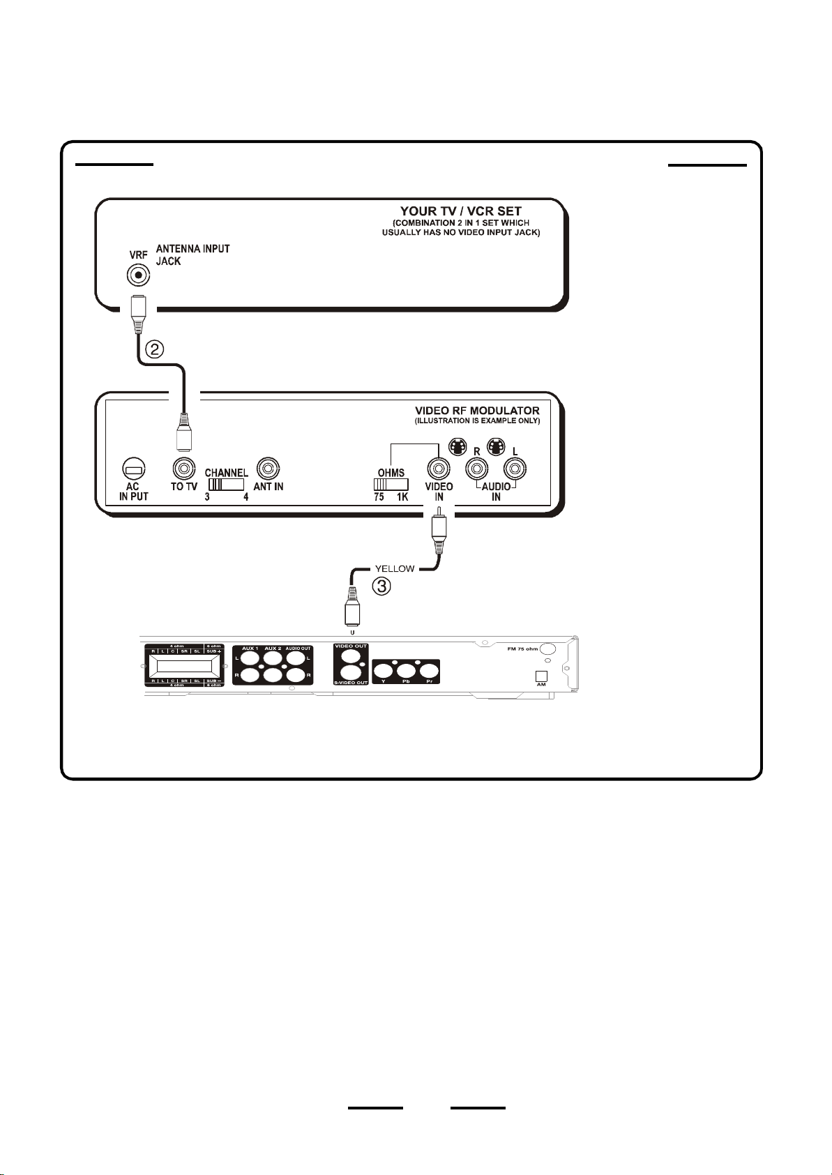
TV/VCR COMBINATION CONNECTION
IF YOU OWN A TWO-IN-ONE CO MBIN ATIO N TV/ VCR
NOT E:
A V i deo RF Modu l ato r is
need ed for a ny TV /VCR
combined set which does
not have VIDEO & AUD IO
i npu t j a cks o r a component
jack. S om e TV/VCR sets
h a v e V IDE O & AU D IO
input. For these sets you do
not need an RF Modulator.
The signa l provided by an
RF modulator is never as
sharp as a direct connection
into a TV with a VIDEO input
jack or component j a ck.
1. Connect the 5 sat e llite speakers and subwoofer as shown on Page 5
2. Ins ert the RF Mo du lator s antenna cable (not included ) into the ANTENNA jack on the back of you r TV/VCR
player, and to the TV OU T jack of your V IDEO RF MODU LATOR.
3. Connect the video c ab le ( y e ll o w ) t o t he V ID EO OU T j a ck on t he ba ck o f y ou r D VD HOME THEATRE S Y S T EM , and
into the VIDEO IN jack on your VI DEO RF MODU LATOR.
4. I ns er t t he AC power cord into an AC s ock et, th e STANDBY indicator will turn on in red au tomatically.
5. P ress the ON/STANDBY button o n th e main s et o r o n th e remo te co ntrol to tu rn on the set, and the STANDBY
indicator w i ll b e o f f.
6. S e l ec t y o ur TV s Video cha nnel to match y our RF M odu lator s Video channel (see th e NOTE on pag e 23 ).
7. Go to Page 32 for playing DVDs (discs).
,
,
,
.
14
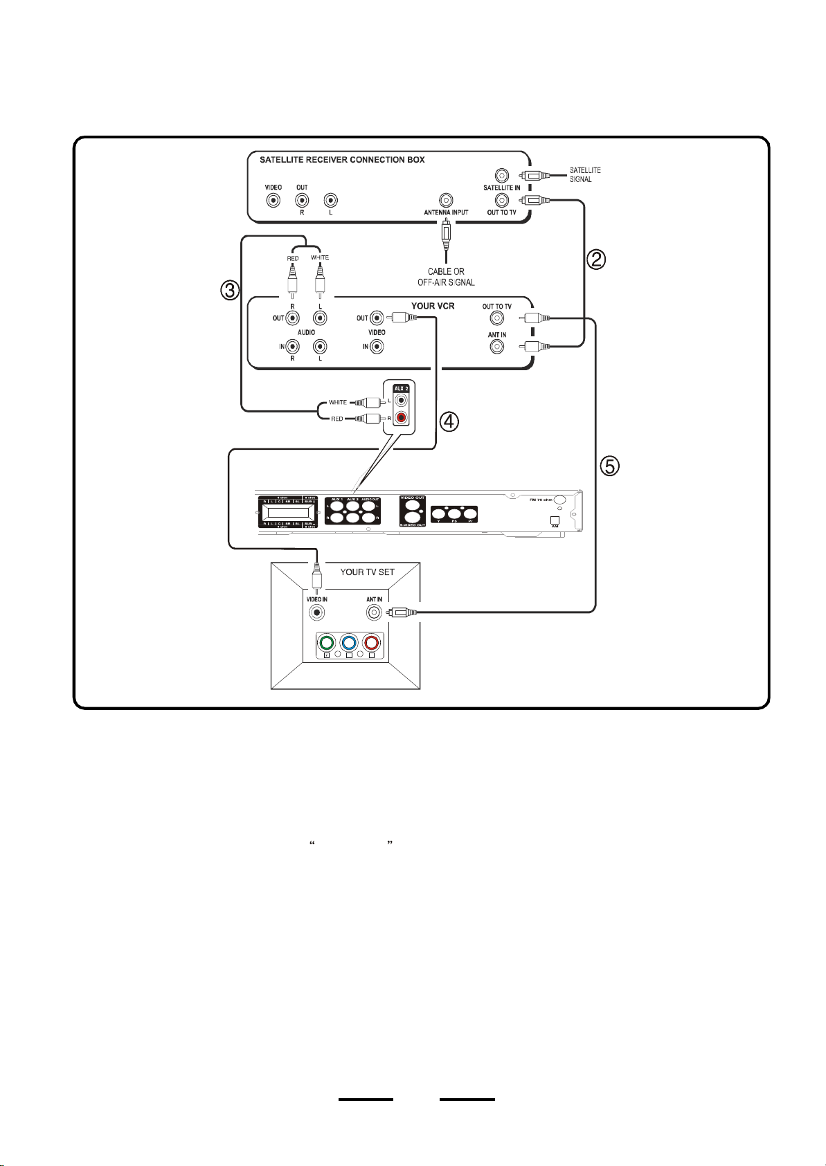
TV+VCR+SATELLITE RECEIVER CONNECTIONS
Audio Cable
Component YUV
Pb Pr
1. Co nnect the 5 satellite spea kers and sub woo fe r as shown on Page 5.
2 . Use an antenna cable to connect t he antenna outpu t on the satellit e receiver to the antenna input on the VCR the
same as you h ave it connected now. Th is DVD HOME THEATRE S YS TE M d oe s n ot c h an ge an y an ten na co nn ec tio ns.
3. Insert the s te reo audio cables (in clud ed ) into the HOME THEATRE A UX 1 o r AU X 2 A UD IO I NP UT L ( L e ft = W h i te ) a nd
R (Right=Red) jacks and into the corres ponding AUD IO OUT jacks on your VCR, this will allow your VCRs sound
to p lay th ro ugh y our HO ME THEATRE SYS TE M.
NOTE: Yo ur VCR s te reo sou nd w ill c ome out of 5 spea ke rs plus s ub woo fer since the factory s defau lt
setting for the sound output is PRO LOGIC . Press the SURROUND button if you want to return to STEREO
(2 c hannel) sound output, and the sound will on ly come out of 2 speakers plus subwoofer (probably best for
VCR soun d).
4. Insert the video c ab l e ( y e ll o w ) i n t o t h e V I DEO O U T j a ck o n t h e ba c k o f y ou r VCR, and i n to the V IDE O
y o u r T V .
5 . Con ne ct VC R to yo ur TV u s ing a co ax ial
6. Connections of your other antenna cables are not changed when you add your DVD HOME THEATRE SY ST EM.
7. Insert the AC power cord into an AC s ock et, the STANDBY indicator will turn on in red automatically.
8 . P r e s s t he O N / S TA N D BY button on the main set or o n the remote control to turn on th e set, and the STANDBY
indicator will be o ff, the n press the SOURCE button repeatedly until AUX 1 or AUX 2 appear on the front panel display.
9 . S e l e c t y o ur TV s vid eo ch ann el or p rev iou sly u s ed VC R v ie w in g c han ne l (s e e P ag e 2 3).
10 . To play DVDs, remember to press the SOU RCE button until the DVD icon sho ws on the front pane l display.
your
,
antenna cable.
,
,,
IN jack on
15
 Loading...