

Page 1
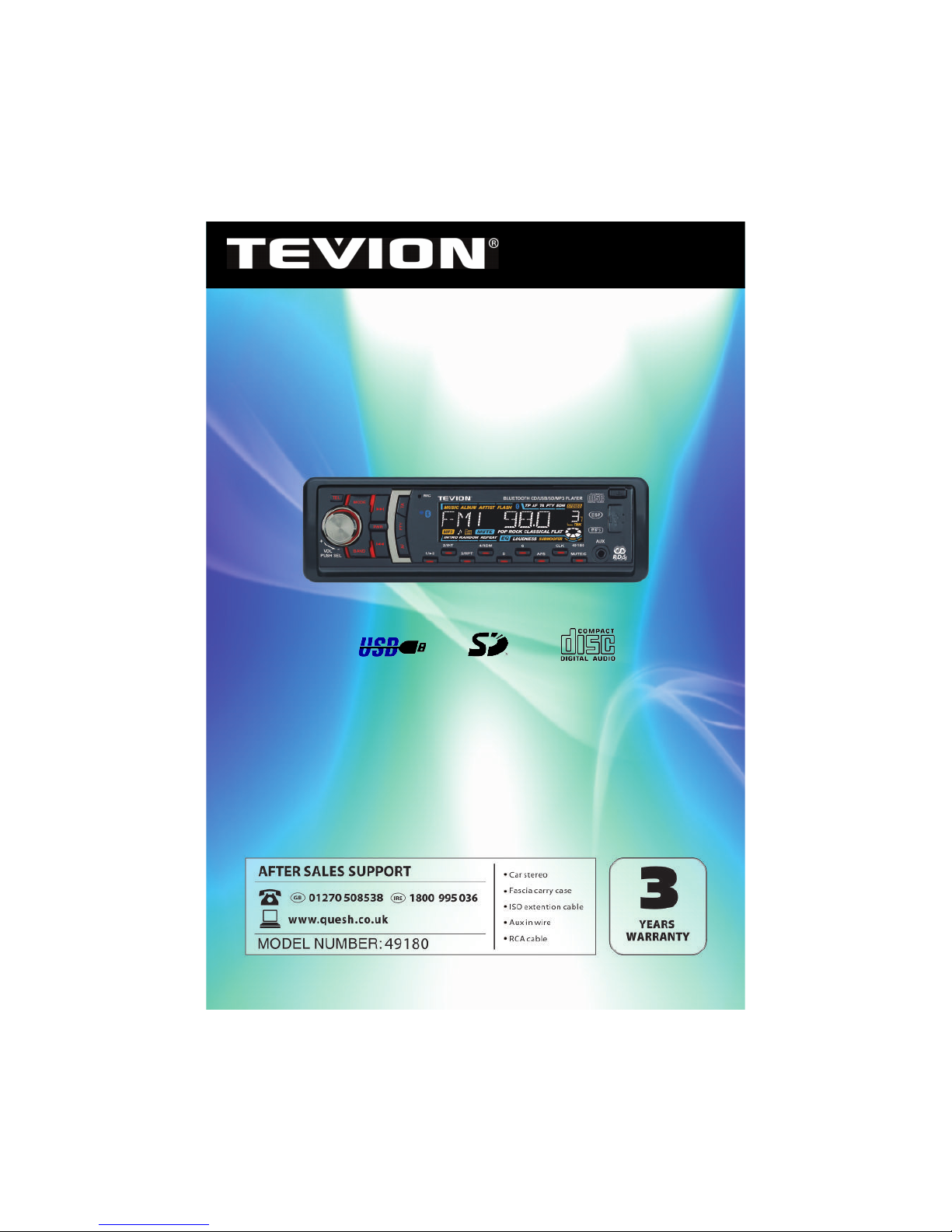
Car CD/MP3 Radio with Bluetooth
with USB,SD and Front Aux input
Now you have purchased a Tevion® product you can
rest assured in the knowledge that as well as your 3
year parts and labour warranty you have the added
peace of mind of dedicated helplines and web support
User Guide
49180
Page 2
Welcome Section……………………………………....3
Precautions………………………………………….....4
Before You Install……………………………………..5-6
Installation…………………………………………....7-8
Wiring Diagram………………………………………..9
Location of the Controls…………………………….....10
Basic Operation……………………………………....11-15
Bluetooth Operation…………………………………..16
CD/MP3/USB/SD Operation………………………...…17
FAQ…………………………………………………….18
Technical Specication………………………………..19
Warranty……………………………………………….20
Fault Report Card………………………………....……21
Contents
2
Page Number
Page 3
Congratulations!
You have made an excellent choice with the purchase of this quality
Tevion® brand product. By doing so you now have the assurance and
peace of mind which comes from purchasing a product that has been
manufactured to the highest standards of performance and safety,
supported by the high quality standards of Aldi.
We want you to be completely satised with your purchase so this
Tevion® product is backed by a comprehensive manufacturer’s 3 year
warranty and an outstanding after sales service through our dedicated
Helpline. We hope you will enjoy using your purchase for many years to
come. If you require technical support or in the unlikely event that your
purchase is faulty please telephone our Helpline for immediate
assistance. Faulty product claims made within the 3 year warranty
period will be repaired or replaced free of charge provided that you
have satisfactory proof of purchase (keep your till receipt safe!). This
does not affect your statutory rights. However, be aware that the
warranty will become null and void if the product is found to have been
deliberately damaged, misused or disassembled.
Welcome Section
3
Electric and electronic equipment (EEE) contains materials,
parts and substances which can be dangerous to the
environment and harmful to human health if not disposed of
correctly. Please contact your local authority for details of
correct disposal operating in your area. The product should
not be disposed of in household waste.
Do not dispose of used batteries in household waste. Please
contact your local authority for details of disposal / recycling
schemes in your area.
Page 4
Precautions
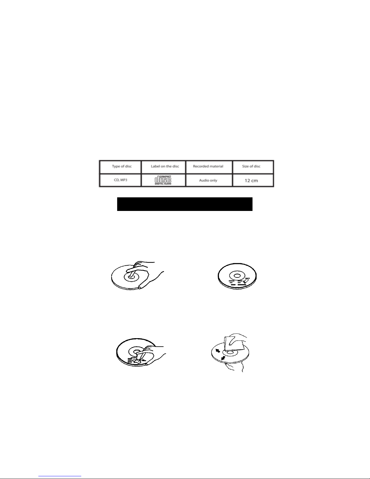
• This unit will only play the following discs.
• This unit does not play les that have Digital Rights Management (DRM).
• If you have les that have Digital Rights Management (DRM) you should consult
with the vendor that you purchased les from for instructions on proper use.
4
Never allow children to play with electrical equipment
Care of Discs
Do not use CDs with labels or stickers
attached. The label may leave a sticky
residue when it begins to peel.
Clean the discs with a soft
cleaning cloth. Wipe each disc
from the centre out.
Do not use a CD with paste or
ink residue on it.
Handle the disc by its edge to
keep the disc clean. Do not
touch the disc’s surface.
Page 5
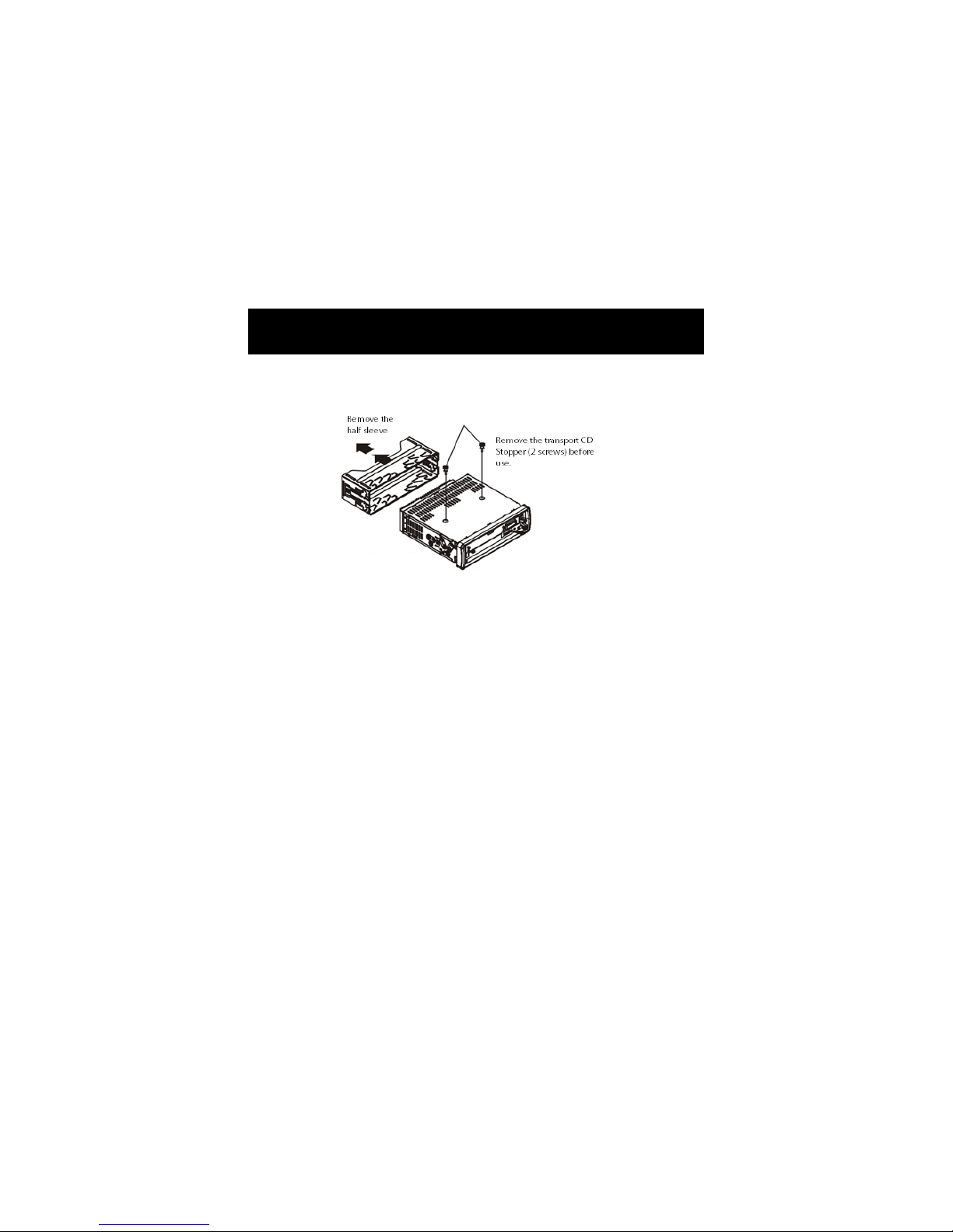
Before You Install
IMPORTANT: Remove the two transport screws from the top of
the unit before installation.
.
5
Notes on Installation
• Disconnect negative battery terminal before starting installation. Consult the
vehicle owner’s manual for proper instruction.
• The unit is designed for a 12Volt DC negative ground operation system only.
• Be sure to connect the colour coded leads according to the diagram.
Incorrect connections may cause the unit to malfunction or damage the
vehicle's electrical system.
• Be sure to connect the negative (-) speaker leads to the negative (-) speaker
terminal.
• Never connect negative (-) speaker leads to chassis ground.
• The unit is only designed for use with 4 speakers. Do not combine output for
use with 2 speakers. Do not ground negative speaker leads to the chassis
ground.
• Make sure all the connections are correct before turning on your unit.
• When replacing the fuse(s), the replacement must be of the same amperage
as shown on the fuse holder.
• Do not block vents or heater panels. Blocking them will cause heat to build
up inside and may result in re.
• After completing the installation and before operating the unit, reconnect
the battery.
• Then press the (RES) button with a pointed object, such as a ball-point pen to
set the unit to its initial status.
Please remove the screws before installing the radio; Failure to do so will result in
the CD deck rejecting the disc. Please refer to the illustration below:
Page 6
Before you Install
Car audio equipment installations can be troublesome at times, even to the
most experienced of installation technicians. If you are not condent working
with electrical wiring, removing and reinstalling interior panels, carpeting,
dashboards or other components of your vehicle, please call our customer
support number 01270 508538 and we will recommend tters in your area.
6
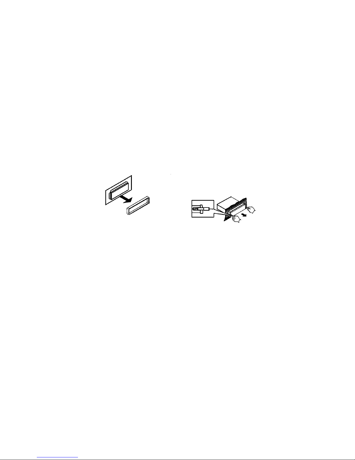
1. Remove the outer trim frame.
Din Front Mount
2. Insert the keys supplied with the old
unit into both sides of the unit as
shown in gure below until they click.
Pull to remove the old unit from the
dashboard.
DO NOT DISCONNECT WIRES
AT THIS TIME!
3. Mark the polarity of the speaker wires. Marking the polarity of the speaker
wires will make it easier to connect the existing speakers to your car radio.
Consult wiring diagram of existing head unit before disconnecting any
wires. If you are not positive of the polarity of the existing wires from the
speakers to the head unit, install new wires.
a. While the old unit is playing, disconnect the wires from one speaker.
b. Take a length of masking tape and fold it around the wire so it forms a ag.
c. On the masking tape mark the polarity of the speaker wires (+ & -), as well as
left or right and front or rear.
d. Double check that you marked the rst speaker correctly by checking
that the speaker wires are the same at the head unit.
e. Repeat the procedure for all of the speakers.
f. Mark the power, ground and any other wires also.
Page 7
Installation
7
WARNING!
Disconnect negative battery terminal from battery before starting
installation. Consult the vehicle owners manual for proper instructions.
Note 1:
Mark the polarity of the existing speaker wires before disconnecting battery.
Note 2:
Remove the two transport screws from the top of the unit before installing.
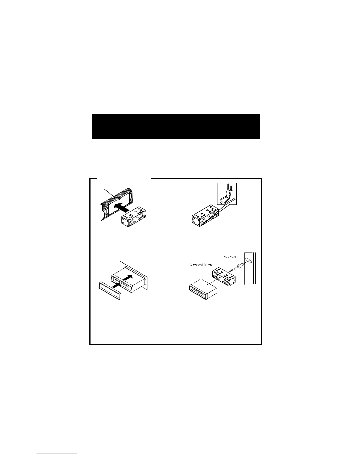
Din Front Mount
1. After removing the old radio and
mounting sleeve, insert supplied
mounting sleeve into opening.
2. Bend the tabs on the mounting
sleeve to keep the mounting
sleeve rmly in place.
3. Attach wires from the unit to existing
wires. See wiring connections
diagram. Insert radio into dashboard.
Then apply the trim face to the
outside of the radio.
4. Support radio using
supplied rear mounting
bolt and steal bar. See parts
list.
Page 8
Installation
8
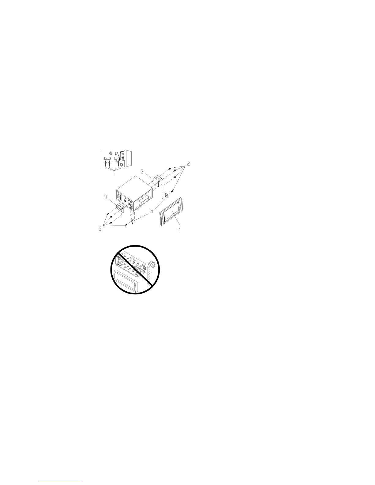
Din Rear-Mount
Installation using the screw holes on both sides of the unit.
1. Screw holes on the side of the unit.
2. Screws. Use either truss screws
(5x8mm) or ush surface screws
(4x8mm), depending on the shape
of the screw holes in the bracket.
3. Vehicle factory mounting bracket.
4. Dashboard or console.
5. Hook (remove this part).
2 x Keys
1 x Aux in wire
1 x Fascia carry case
1 x Flat Washer
1 x Metal Screw
1 x Metal Support Strap
Note:
The mounting sleeve, outer trim ring and the
mounting strap are not used for this method of
installation.
Supplied Parts
Page 9
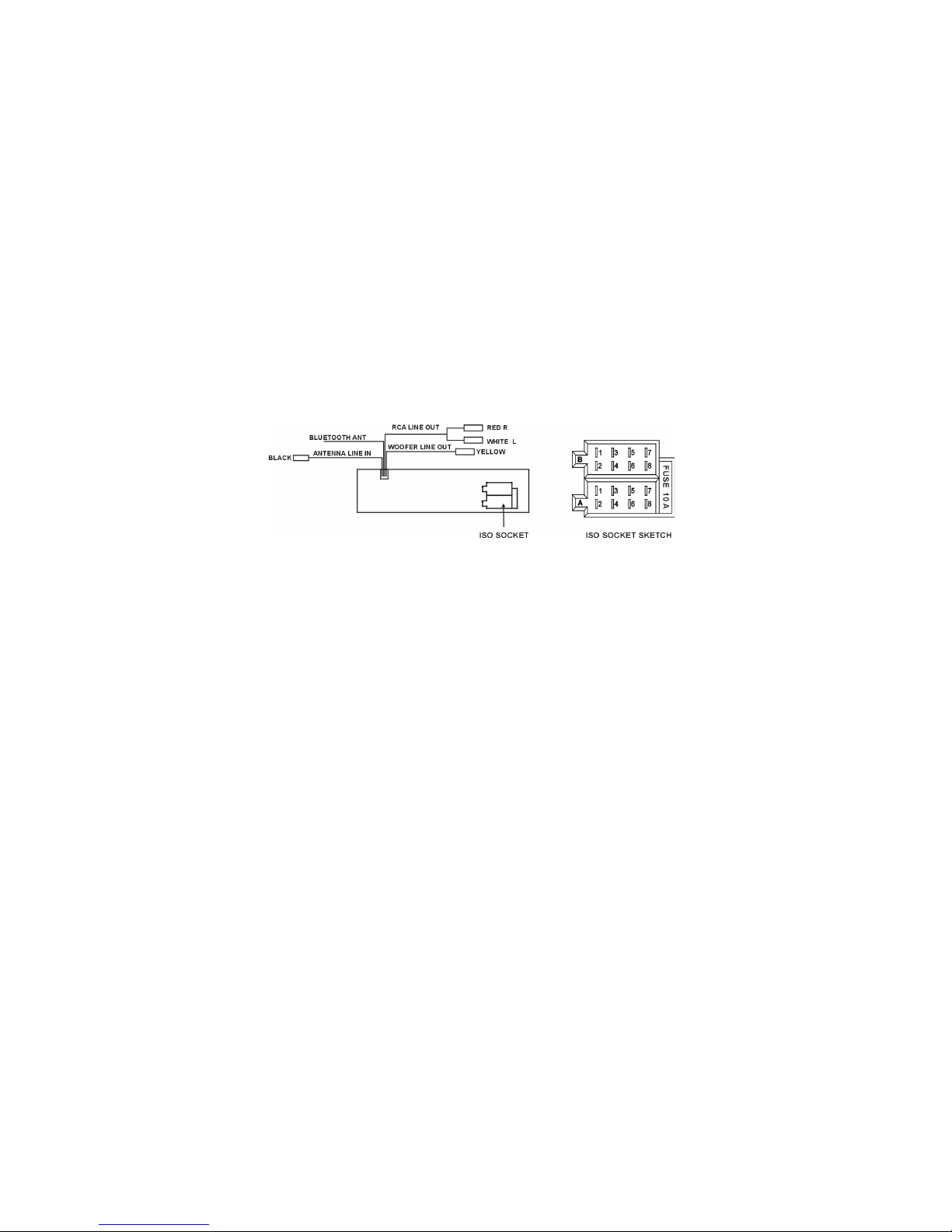
9
Wiring Connection
Make sure that you have a good chassis ground. Good ground connections will
eliminate most electrical noise problems. A good chassis ground requires a
tight connection to the vehicle's metal chassis. The area around the ground
connection should be clean, bare metal without rust, paint, plastic, dust, or dirt
for a good electrical connection.
CONNECTOR A
1.
2.
3.
4. Memory +12V
5. Auto Antenna Output
6.
7. 12V (To Ignition Key)
8. Ground
CONNECTOR B
1. Rear Right Speaker (+)
2. Rear Right Speaker (-)
3. Front Right Speaker (+)
4. Front Right Speaker (-)
5. Front Left Speaker (+)
6. Front Left Speaker (-)
7. Rear Left Speaker (+)
8. Rear Left Speaker (-)
Speaker Wiring Notes
• Follow the above wiring diagram to install the head unit with new or
existing speakers.
• This unit is designed for use with four speakers with an impedance between
4Ohms to 8Ohms.
• An impedance load of less than 4 Ohms could damage the unit.
• Never Bridge or combine the speaker wire outputs. When not using four
• speakers, use electrical tape to tape the ends of the un-used speaker
outputs to prevent a short circuit.
• Never ground the negative speaker terminals to chassis ground.
Page 10
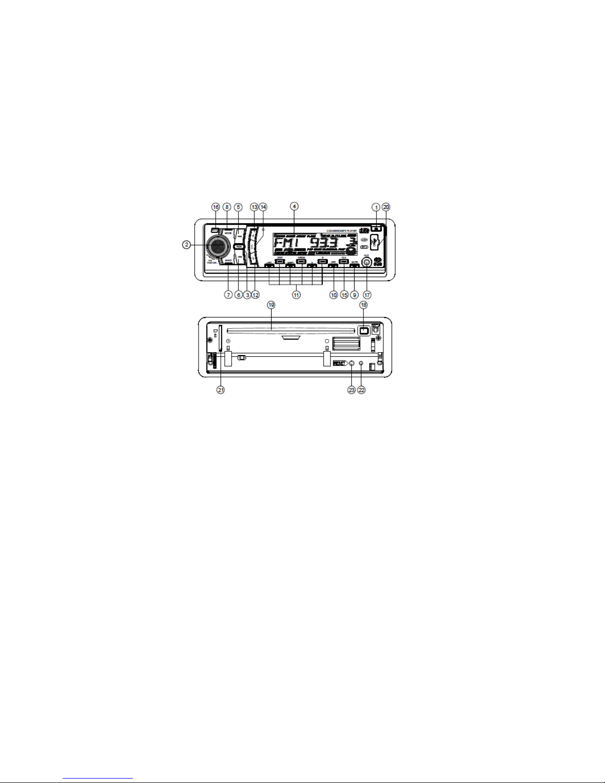
Location Of The Controls
10
15. CLK button
16. TEL button
17. AUX INPUT Jack
18. EJECT button
19. CD slot
20. USB port
21. SD slot
22. Anti-theft LED indicator
23. RESET button
1. OPEN button
2. SEL button and VOL dial
3. POWER button
4. LCD
5&6. >>| and |<< button
7. BAND button
8. MODE button
9. MUTE button
10. AP button
11. TOP/PLAY/PAUSE, INT, RPT,
RDM and 1-6 Number buttons
12. AF button
13. TA button
14. PTY button
Page 11

Basic Operation
11
1. OPEN BUTTON
Press the OPEN button to fold down the fascia panel.
Then a disc can be inserted into the disc slot or ejected by pressing the EJECT
button.
After ipping down the fascia panel, push it towards the left, then pull the
right side of the panel towards you to remove it from the main chassis.
2. SEL BUTTON (Select) and VOL DIAL
a. Press the SEL button briey to cycle through the following options.
>VOLUME>BASS>TREBLE>BALANCE>FADER>
To change the setting of your selection simply turn the VOL dial until you reach
your desired level and press the SEL button to conrm your selection. To exit
the menu simply wait 5 seconds and the display will return to tuner or CD
mode.
b. If you press and hold the SEL button for around 2 seconds you are able to cycle
through the following options.
>TA (ALARM/SEEK)>PI (SOUND/MUTE)>RETUNE (LONG/SHORT)>MASK (DPI/
ALL)>BEEP (ON/OFF)>USER SET (FLAT/CLASSIC/ROCK/POP)>VOL (LAST/
DEFA)>MONO/STEREO (FM MODE ONLY)>LOUD (ON/OFF)> LOCAL/DX (FM
MODE ONLY)>CLK (ON/OFF)>CLK (12/24)
After selecting the desired mode simply turn the VOL dial to select your
preferred choice.
b1. TA SEEK/TA ALARM:
TA SEEK mode: When a newly tuned radio station does not receive TP
information for 5 seconds, the radio retunes to the next station which has a
different PI to the last station, but has the TP information.
When TP information is no longer available for the current station it will start
to retune in 90 seconds or 150 seconds depending on your RETUNE LONG/
SHORT setting.
TA ALARM mode: When this mode is selected the auto retune function is not
available. Only a double beep (ALARM) will be heard. When a newly tuned
radio station does not have TP information for 5 seconds, beeps are sounded.
Page 12

Basic Operation
12
b2. PI SOUND/PI MUTE
PI SOUND mode: When driving in built up areas you may experience different
PI sounds which will be heard for less than a second. This is due to different PI
codes being received from the same AF source (reecting signals).
PI MUTE mode: Rather than hearing different sounds the radio will mute for
less than a second.
b3. RETUNE LONG/RETUNE SHORT
The amount of time before an automatic TA or PI search is enabled. When PI
information is not received for the selected amount of time the radio will start
to retune to the next available PI station. If no PI station is found the radio will
go back to the previous station and wait 4-5 minutes until the PI code is
received.
RETUNE L: 150 Seconds.
RETUNE S: 90 Seconds.
b4. MASK DPI/MASK ALL:
MASK DPI mode: Masks only the AF which has different PI.
MASK ALL mode: Masks the AF which has different PI and NO RDS signal with
high eld strength.
b5. BEEP ON/BEEP OFF
BEEP ON mode: A beep is sounded when any key is pressed.
BEEP OFF mode: The beep sound is disabled.
b6. VOL LAST/VOL DEFA
VOL LAST mode: The radio switches on at the actual volume it was when it was
switched off.
VOL DEFA mode: After pressing SEL button, AVOL will be displayed. Then you
can pre-select a constant switch-on volume by using the VOL dial.
b7. CLK ON/OFF
CLK ON: Clock will always show on the display when power off.
CLK OFF: Clock will disappear on the display when powered off.
b8. CLK 12/24
CLK 12: Clock displays in 12 hour mode.
CLK 24: Clock displays in 24 hour mode.
3. POWER ON/OFF
When the unit is off you can turn the unit on by pressing any button on the
fascia apart from the open button. You can also turn the stereo on by inserting
a disc, SD Card or USB Stick. To turn the stereo off pres and hold the power
button.
Page 13

Basic Operation
13
4. LCD DISPLAY
5,6. TUNE, SEEK and TRACK BUTTONS
Press the >>| or |<< button briey to manually tune up or down for the desired
radio station frequency.
Press and hold >>| or |<< to auto tune up or down.
7. BAND BUTTON
During radio mode, press the BND button briey to select the radio
broadcasting band you would like.
8. MODE BUTTON
Press the mode button to change between, tuner, disc (when disc is loaded),
SD Card (when SD Card is inserted, USB (when USB device is inserted), BT
READY mode (when the Bluetooth is not connected, it shows as NO CON) and
AUX mode.
9. MUTE BUTTON
This button turns mute on or off.
Press the mute button to suppress the loudspeaker temporarily, and press
again to resume listening. You can also exit mute by using MODE, SEL buttons
or the VOL dial on the fascia panel.
10. AP BUTTON (Auto-Storage/Preset Scan)
If you press and hold the button for more than one second it will scan and
store 6 stations into your presets. You can do this in each band.
11. PRESET STATION MEMORY
You can go to any preset station by pressing one of the buttons marked 1-6. To
store the station that you are currently listening to press and hold the desired
preset location (1-6) until you see the number that you are holding displayed
on screen.
12. AF (ALTERNATIVE FREQUENCIES) BUTTON
You can turn the AF mode on or off by briey pressing the AF button.
AF Displayed: AF Switching mode is on.
AF Not Displayed: AF Switching mode is off.
AF Flashing: AF switching mode is, but no RDS information is being received.
Page 14

Basic Operation
14
When AF mode is selected, the radio checks the signal strength of AF all the
time. The interval of checking time of each AF depends on the signal strength
of the current station, from a few minutes for strong signals to a few seconds
for weaker stations. Whenever a stronger frequency is found the radio will
switch over to that frequency for a short time., and the new frequency is
displayed for 1-2 seconds, because the mute time of AF switching or checking
time is very short, it is almost inaudible. During FM mode, when AF is on ,
SEEK, SCAN, AUTO-MEMORY functions can only receive and save RDS
programs.
If you press and hold the AF button the AF mode is converted to REGION ON/
OFF mode.
REGIONAL MODE ON:
AF switching or PI SEEK is implemented to the station which has PI codes that
are the same as the current station. (PI CODE is checked when AF CHECK is in
progress)
REGIONAL MODE OFF:
The regional code in the format of PI is ignored when AF switching or PI SEEK
is implemented. (PI CODE and COVERAGE AREA is not checked when AF
CHECK is in progress)
13. TA (TRAFFIC ANNOUNCEMENT) BUTTON
a. You can turn TA mode on or off by pressing the TA button, if TA is activated you
will see TA on the LCD display., it will then begin to seek a TA station and TA
SEEK will be displayed on the LCD for a moment.
b. When a traffic announcement is transmitted:
c. If the stereo is in SD, USB or disc mode, it will switch to radio temporarily.
d. If the volume is below 20, the volume level will raise to 20 for the
announcement and return to its previous state.
e. You can cancel the announcement by pressing the TA button.
14. PTY (PROGRAM TYPE) BUTTON
This radio will allow you to select the type of programme required, and will
search for a station broadcasting that type of programme. Press the PTY
button once to show the music type. Then press 1-6 button to choose the
different music types available. Each number key will show 2 different
speech programme for you to choose.
Page 15

Basic Operation
15
15. CLOCK BUTTON
Press the CLK button briey to display the time for 5 seconds on the display, it
will then revert back to the previous display until the CLK button is pressed
again.
If you press and hold the CLK button until the real time ashes on the display,
you can adjust the time by using the VOL dial and SEL button.
16. TEL BUTTON
17. AUX IN
For connection of other audio device.
18. EJECT BUTTON
Before operating the unit for the rst time, or after replacing the car battery,
you must reset the unit.
This will erase any stored data on the stereo.
19. CD Slot
20. USB Port
21. SD Card Slot
22. Anti-theft LED indicator
23. RESET button
Page 16

Bluetooth Operation
16
Pairing
To pair your mobile phone with a Bluetooth device, simply activate the
Bluetooth function on your mobile phone and search for devices. When the
stereo has been found it should show as Car Kit, when you try to connect, it will
ask for a password. The default password is 0000. When you have successfully
paired your phone the message BT READY will be displayed followed by the
mobile number. When the phone has successfully connected you will see a blue
led on the display ashing. This LED will turn to solid when you are on a call or
disappear when you disconnect from the stereo.
Dial
To make a call simply press the TEL button and enter the number you wish to
call using the remote control. When your ready to make the call press TEL again,
to end the call simply press clear.
Accept/Reject/Hold/End Call
Accept – Press the Tell button
Reject – Press the CLEAR button
To Transfer A Call Either From The Stereo Or To The Stereo – Press and hold TEL
for around 3-4 seconds.
Auto Connect
This unit support the “Auto Connect function”.
Page 17

CD/MP3/USB/SD OPERATION
17
SKIP UP/ DOWN BUTTONS
Press the >>| button briey to play next track.
Press the |<< button briey to play the previous track
You can fast forward or rewind by pressing and holding these buttons.
AP BUTTON
When playing USB or SD devices you can select which song you want to play rather
than skipping through each song. To do this simply press the APS button and TRK
000 will be displayed. Use the VOL dial to make your selection then press the APS
button to move onto the next number. Once you have selected which track you
want to play, press the SEL button and your choice will then start to play.
PLAY/PAUSE, INT, RPT, RDM BUTTONS
Press the >|| button to pause or resume play. You can press and hold this button to
go directly to the rst song on the disc, USB or SD device.
You can use the INT button to sample the rst 10 seconds of each song. To activate
this feature simply pres the INT button, to deactivate this function press the INT
button again.
You can use the RPT button to repeat a song or repeat an album. To do this simply
press the RPT button once to repeat one song and RPT ONE will be visible on the
Display, or twice to repeat an album and RPT ABM will be visible. When repeat is
Active you can disable it by pressing the RPT button and RPT OFF will be displayed.
During normal playback of MP3 Disc, SD or USB you can use preset buttons 5 and 6
to move up or down 10 tracks at a time.
AUX INPUT JACK
Press the mode button to select AUX input mode. Then you can connect any
Compatible MP3 player. To skip songs or adjust the master volume while in this
mode you will need to use the connected device.
EJECT Button
Used to eject a disc from the disc tray.
Page 18
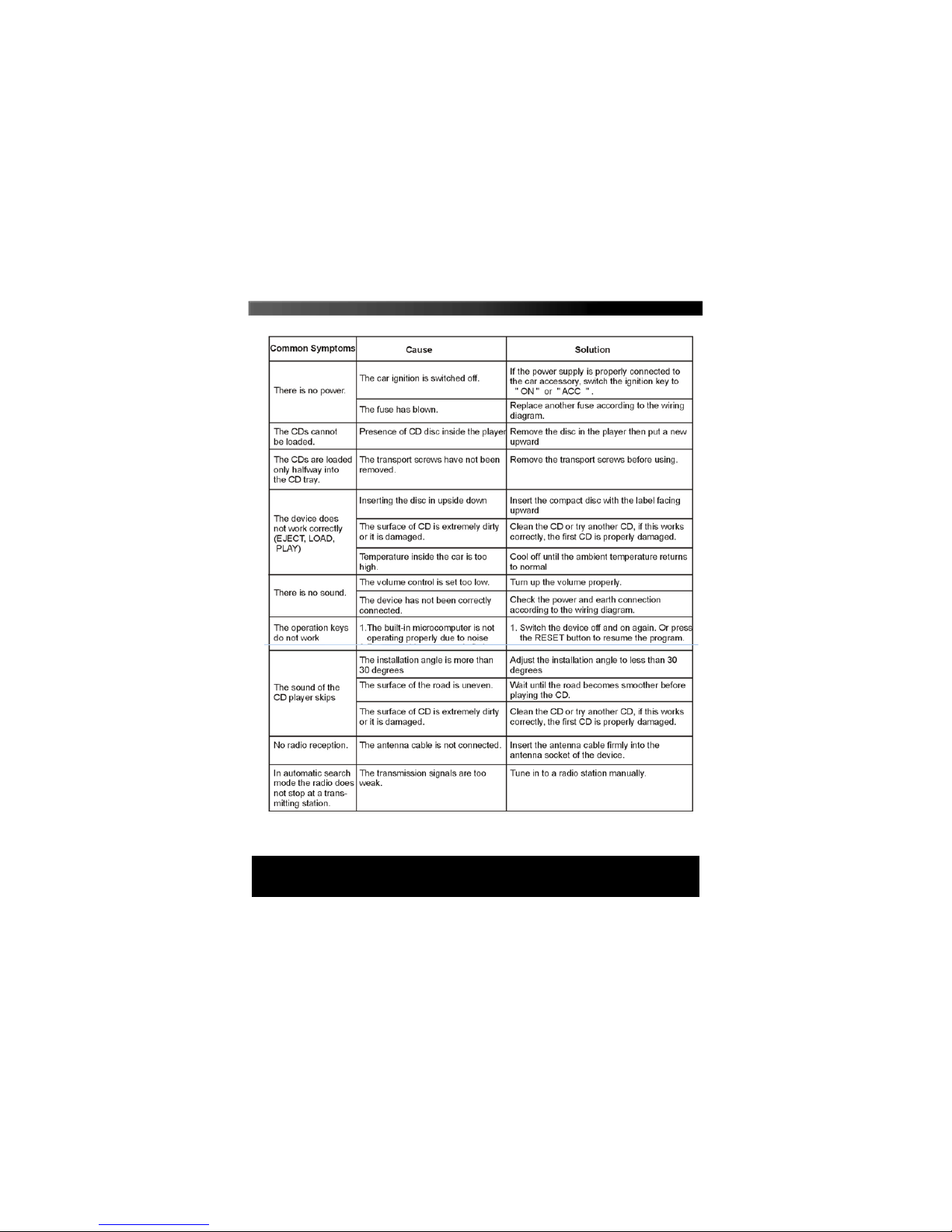
FAQ ’S
18
If your problem is not listed, please call our customer support team.
Page 19

TECHNICAL SPECIFICATION
19
GENERAL
Power supply requirement....................................................DC 12V
Current consumption..........................................................10A MAX
Maximum power output.......................4 X 40W(Measured at 14.4V)
Number of channels.........................................................2 STEREO
Chassis dimensions...................................178[W] X 50[H] X 165[D]
FM SECTION
Frequency range..................................................87.5MHz -108MHz
Usable sensitivity..........................................................................3uV
I.F Frequency.......................................................................10.7MHz
AM SECTION
Frequency range.................................................522KHz - 1620KHz
I.F Frequency........................................................................450KHz
Usable Sensitivity......................................................................40dB
LINE - OUT
Output........................................................................MAX 1200mV
CD/SD or USB PLAYBACK
System................................................................MP3 audio system
Usable disc..................................................CD/CD-R/CD-RW/MP3
Frequency response.............................................20-100Hz <= 5dB
10-20KHz <= 5dB
Signal to noise ratio(CD)...............................................50dB [1KHz]
Page 20
 Loading...