

Page 1
MANUAL DE SERVICIO
SERVICE MANUAL
TECNICAS EVAPORATIVAS, S.L. MS.40.05
Polg. Ind. Can Humet / Joan Mirò 1 / Polinyà (Barcelona) / Tel. 937 133 573 Fax. 937 133 160
abcde
• Expedición
• Manipulación
• Asentamiento
• Instalación
TORRES DE REFRIGERACIÓN
Series TVAP / TVAP-SPL
COOLING TOWERS
Series TVAP / TVAP-SPL
• Shipment
• Lifting
• Placement
• Instalation
• Funcionamiento
• Mantenimiento
• Operation
• Maintenance
- 1 -
Page 2
GENERALIDADES
INTRODUCTION
El contenido de éste manual es aplicable a las torres de
refrigeración de las series TVAP y TVAP-SPL, que deberá ser
leído atentamente por el personal técnico responsable, antes
de la manipulación de éstos equipos
VERIFICACIONES
Para asegurarse de la ausencia de daños y/o pérdidas
durante el transporte, a la recepción del equipo, deberán
verificarse las partes siguientes:
• Superficie exterior
• Deflectores de entrada de aire
• Flotador de la válvula de reposición de agua
• Malla metálica situada sobre la conexión de salida de
agua.
• En los equipos expedidos en dos secciones, caja de
tornillería y accesorios. (Ubicada en el interior de la
bandeja)
Cualquier anormalidad observada a la recepción del
equipo, deberá ser anotada en el documento de
recepción y comunicada urgentemente al suministrador.
EXPEDICION Y MANIPULACION
Modelos TVAP / TVAP-SPL del 008 al 026
The content of this manual is applicable to the cooling towers
series TVAP and TVAP-SPL, it will be read thoroughly by the
responsible technical personnel, before the manipulation of
these equipment.
CHECKING
To make sure of the absence of damages and/or losses
during the transport, to the reception of the equipment, the
following parts will be verified:
• External surface
• Air intake grids
• Float valve of make-up water connection
• Filter in inox. of water outlet connection
• In the equipment shipping in two sections, screws and
accessories box. (Located inside the basin)
Any abnormality observed to the reception of the
equipment, it will be written down in the reception
document and communicated urgently to the supplier
SHIPMENT AND LIFTING
Models TVAP / TVAP-SPL from 008 to 026
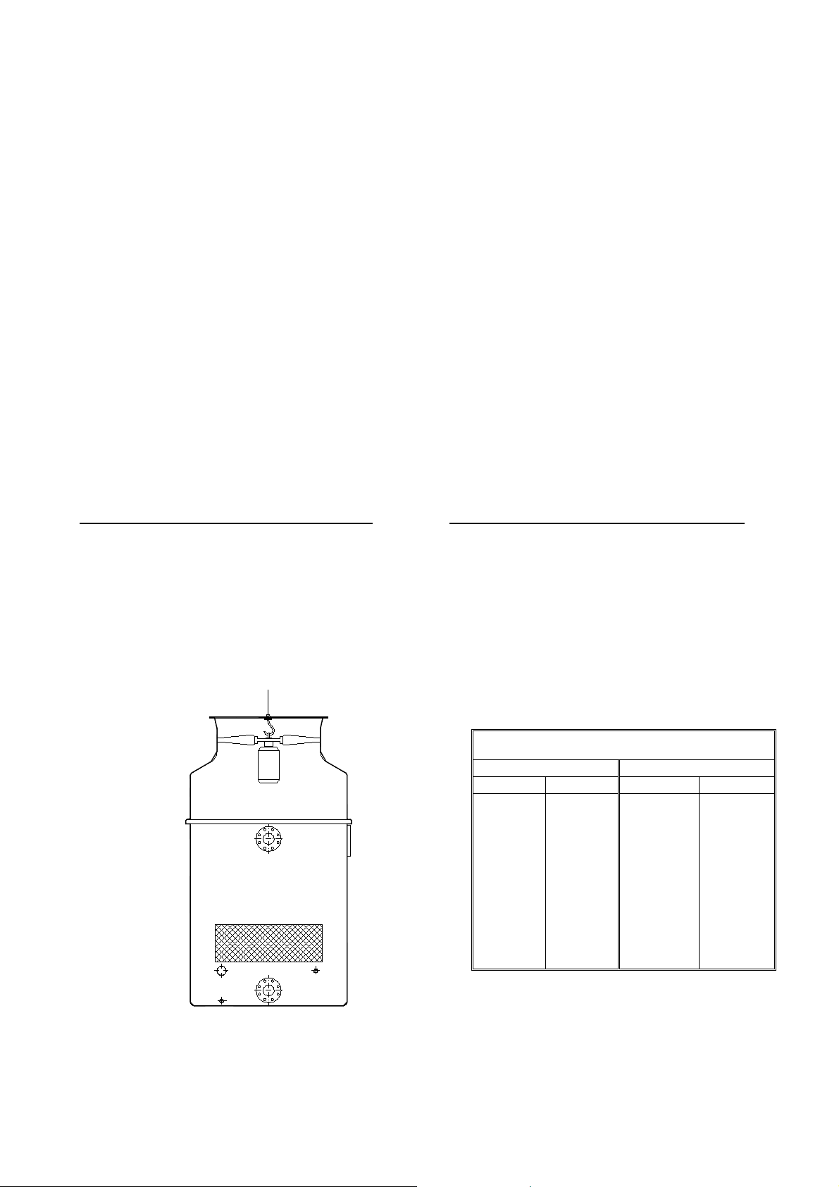
Las torres correspondientes a éstos modelos, se expiden
completamente montadas y situadas sobre palet, lo que
facilita su manipulación.
Para su ubicación final, pueden elevarse suspendiéndolas de
la anilla situada sobre el ventilador, extrayendo previamente
la reja de protección situada sobre el mismo.
The towers corresponding to these models, are shipped
completely assembled located on palet, what facilitates their
manipulation.
For the final location, they can rise lifting of the ring located on
the motor-fan, extracting previously the protection grill located
on the same one.
Pesos en expedición: / Shipped weights:
TVAP TVAP-SPL
Mod.
008
009
010
012
015
016
019
021
024
026
Kg.
145
145
150
155
160
190
190
200
210
215
Mod.
016
019
021
024
026
Kg.
215
220
250
260
265
- 2 -
Page 3
Modelos TVAP /TVAP-SPL del 032 al 078
Models TVAP /TVAP-SPL from 032 to 078
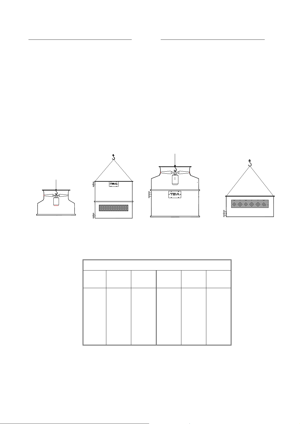
Las torres correspondientes a éstos modelos, se expiden
divididas en dos secciones para facilitar su transporte. Ambas
secciones van situadas sobre palets lo que facilita su
manipulación.
Para facilitar la ubicación final, ambas secciones van
equipadas con elementos de elevación;
Las secciones A, pueden elevarse suspendiéndolas de la
anilla situada sobre el ventilador, extrayendo previamente la
reja de protección situada sobre el mismo.
Las secciones B, pueden elevarse suspendiéndolas de los
cáncamos situados en las cuatro esquinas.
Modelos: TVAP / TVAP-SPL del 032 al 052 Modelos: TVAP / TVAP-SPL del/ 058 al 078
Models: TVAP / TVAP-SPL from 032 to 052 Models: TVAP / TVAP-SPL from 058 to 078
The towers corresponding to these models, are shipped
divided in two sections to facilitate the transport Both sections
is located on palet, what facilitates their manipulation.
To facilitate the final location, both sections is equipped with
elevation elements;
The sections A, can rise lifting of the ring located on the
motor-fan, extracting previously the protection grill located on
the same one.
The sections B, they can rise lifting them of the ring located in
the four corners
Sección A / Sectión A Sección B / Section B Sección A / Section A Sección B / Section B
Pesos en expedición (Kg): / Shipped weights (Kg):
TVAP
032
038
044
048
052
058
062
068
078
Sección
Section
A
150
155
155
165
175
400
410
420
490
Sección
Section
B
230
230
250
250
250
185
185
185
185
TVA -
SPL
032
038
044
048
052
058
062
068
078
Sección
Section
A
150
155
155
165
175
530
540
550
685
Sección
Section
B
275
275
345
345
345
185
185
185
185
- 3 -
Page 4
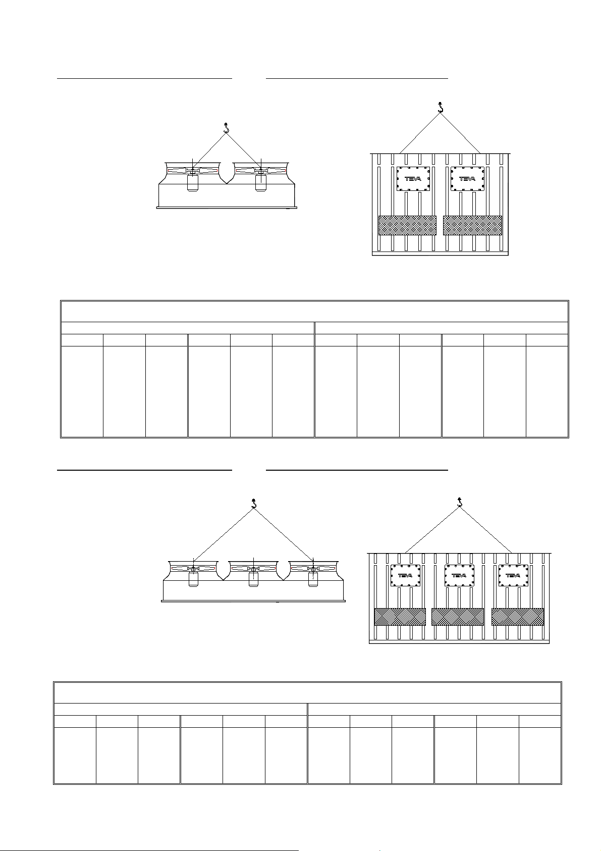
Mod. TVAP / TVAP-SPL del 100 al 350 Mod. TVAP / TVAP-SPL from 100 to 350
Sección A / Section A Sección B / Section B
Pesos en expedición (Kg.): / Shipped weights (Kg.):
TVAP TVAP-SPL
Mod. Sec. A Sec. B Mod. Sec. A Sec. B Mod. Sec. A Sec. B Mod. Sec. A Sec. B
100
110
120
130
200
210
220
290
315
330
360
365
435
445
555
555
590
610
630
670
690
300
310
320
330
340
350
490
500
560
570
600
605
735
775
765
810
795
840
100
110
120
130
200
220
290
315
330
360
365
445
745
745
830
895
860
1015
Mod. TVAP / TVAP-SPL del 400 al 450 Mod. TVAP / TVAP-SPL from 400 to 450
300
310
320
330
340
350
490
500
560
570
600
605
1025
1085
1125
1200
1230
1310
Sección A / Section A Sección B / Section B
Pesos en expedición (Kg.): / Shipped weights (Kg.):
TVAP TVAP-SPL
Mod. Sec. A Sec. B Mod. Sec. A Sec. B Mod. Sec. A Sec. B Mod. Sec. A Sec. B
400
410
420
720
730
825
1095
1155
1135
430
440
450
835
880
890
1200
1180
1250
400
410
420
720
730
825
1515
1610
1665
430
440
450
835
880
890
1770
1815
1935
- 4 -
Page 5
ASENTAMIENTO
PLACEMENT
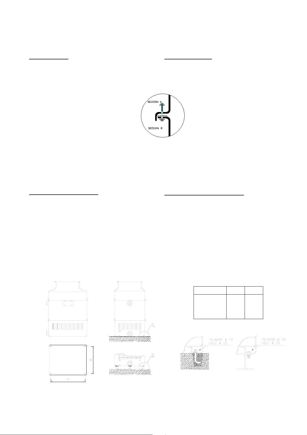
ENSAMBLAJE
En el caso de que por necesidades del transporte las torres
fuesen expedidas en dos cuerpos, deberá procederse al
ensamblaje de los mismos en la forma siguiente:
1º) Colocar sobre una superficie nivelada la sección inferior
de la torre (Sección B).
2º) Asegurarse de que el borde superior no ha
sufrido daños durante el transporte y de que la
guarnición de estanqueidad está colocada en
todo su perímetro.
3º) Elevar la sección superior (Sección A),
siguiendo las instrucciones del capítulo
anterior, asegurándose previamente de que el
perfil inferior no ha sufrido daños durante el
transporte. En el envío de más de una torres
los cuerpos superior e inferior de cada conjunto, van
identificados por etiquetas con una o más flechas que
deberán hacerse coincidir.
4º) Situar la sección superior sobre la inferior haciendo
coincidir los taladros con la ayuda de alguna varilla
metálica.
5º) Colocar los tornillos de unión entre ambas secciones.
Ver figura.
SOPORTES Y ANCLAJES
La mejor bancada para las torres de refrigeración es la
formada por un plano de apoyo, en hormigón o cualquier otr o
material, capaz de soportar el peso total de la torre en
funcionamiento.
Cuando el apoyo deba efectuarse sobre vigas metálicas, es
necesario colocar una viga central, aunque no tenga puntos
de anclaje, equidistante de las dos longitudinales.
Los aparatos deberán ser anclados al plano de apoyo para
contrarrestar la presión del viento.
Las formas de anclaje están indicadas seguidamente.
RE-ASSEMBLING
When TVAE towers are shipped in two sections, they will be
re-assembling as follows:
1º) Place the lower section of the tower (Section B) on a flat
surface.
2º) Being sure that the upper edge has not been
damaged during transportation and that the
closing gasket is placed in all perimeter.
3º) Lift the upper section (Section A), according
to the instructions of the previous chapter, being
sure previously that the lower profile has not
suffered damages during the transport. In the
shipment of two or more towers, the sections
uppers and lowers of each group, are identified by
labels with one or more arrows that will be made
coincide.
4º) Locate the upper section of the tower on the lower one
making holes fit closely together with de aid of metal
pins
5º) Place the screws of union among both sections.
See figure.
SUPPORTS AND FASTENING
The best arrangement for cooling towers is over an even
concrete floor able to support the total weight of the unit in
operation.
If the tower must be installed over metal beams, is necessary
to place a central beam halfway of two longitudinal beams.
The units must be fastened to the ground to resist the wind
pressure.
The fastening means are indicated in the following figures.
Mod. TVAP / TVAP-SPL del 008 al 078
Mod. TVAP / TVAP-SPL from 008 to 078
TVAP A B
008 $ 015
016 $ 026
032 $ 052
058 $ 078
Opción A Opción B
Option A Option B
800
1100
1370
2030
- 5 -
800
1100
1670
1670
Page 6
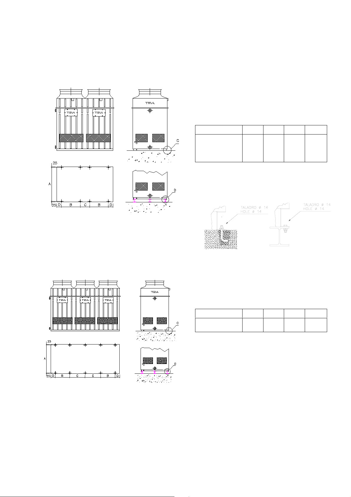
Mod. TVAP / TVAP-SPL del 100 al 350
Mod. TVAP / TVAP-SPL from 100 to 350
TVAP A B C D
100 $ 130
200 $ 220
300 - 320 - 340
310 -330 - 350
1780
1780
2080
2250
900
1200
1200
1200
600
600
750
750
300
300
375
375
Mod. TVAP / TVAP-SPL del 100 al 350
Mod. TVAP / TVAP-SPL from 100 to 350
Opción C Opción D
Option C Option D
TVAP A B C D
400 - 420 - 440
410 -430 - 450
2080
2250
1200
1200
1275
1275
375
375
- 6 -
Page 7
INSTALACIÓN
INSTALATION
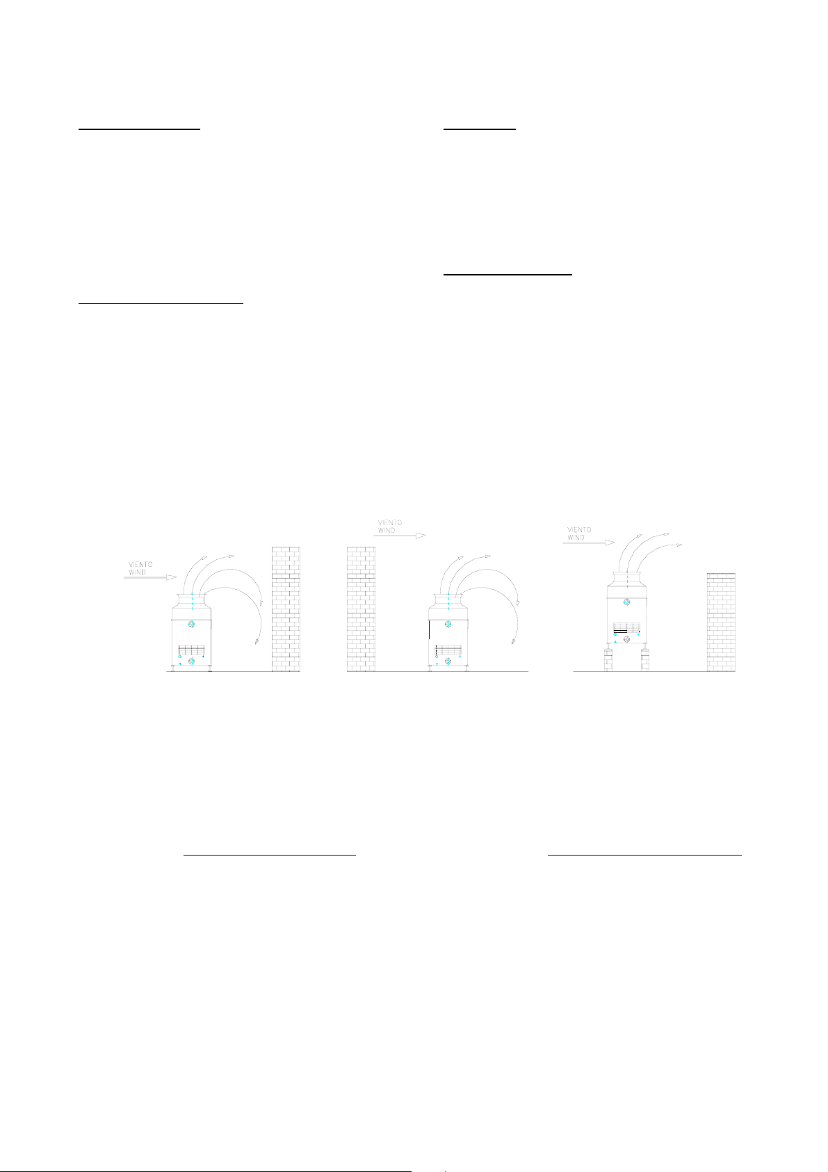
EMPLAZAMIENTO
Siendo las torres de refrigeración aparatos que necesitan una
abundante alimentación de aire, la consideración más
importante que se ha de tener presente en la elección de su
emplazamiento, es que exista una libre circulación de aire
para que sus prestaciones no se vean comprometidas. El
mejor emplazamiento para una torre de refrigeración, es
situarla a los cuatro vientos, sin obstáculos alrededor. Sin
embargo cuando esto no es posible, será necesario respetar
algunas normas esenciales:
Evitar la recirculación del aire. El aire saturado de humedad a
la salida de la torre, debe poder dispersarse libremente en la
atmósfera. Si una parte de éste aire fuese aspirado
nuevamente por la torre, la eficacia de la misma disminuiría
con respecto a las condiciones de proyecto al modificarse la
temperatura húmeda del aire.
Debe evitarse en primer lugar colocar la torre cerca de
paredes u otros obstáculos más altos que la torre misma.
(Ver figuras 1 a 3.). En el primer caso el viento dominante
empujaría al aire contra la pared, recirculando parte del
mismo. En el segundo, la depresión creada por la velocid ad
del viento en la parte inferior de la torre, ocasionaría el mismo
fenómeno. Esta situación puede subsanarse elevando la torre
hasta el nivel de la pared vecina.(Ver figura 3).
LOCATION
Cooling towers need a plentiful supply of air. Therefore the
most important consideration that has to be borne in mind
when choosing where to locate them is the existence of a
supply of freely circulating air that will ensure that their
performance is not impaired. The best place to put up a
cooling tower is right out in the open, without any obstacles
round it. However, when this is impossible, there are certain
essential rules that must be observed:
Avoid recycling the air. The air saturated with humidity that
comes out of the tower must be freely dispersed into the
atmosphere. If part of this air is taken back into the tower, its
efficiency will diminish in comparison with its performance in
the conditions laid down in the project, as the humid
temperature of the air will be different.
The first requirement is not to situate the tower near any walls
or other obstacles that are higher than the tower itself (see
figures 1 to 3). In the former case, the prevailing wind will
push the air against the wall, causing part of it to be recirculated. In the latter case, the depression created by the
wind speed at the bottom of the tower will produce the same
phenomenon. Where such proximity is unavoidable, this
problem can be overcome by raising the tower to the height of
the nearby wall (see figure 3).
Fig. 1 Fig. 2
A los efectos de aspiración de aire, es necesario mantener
una separación mínima ( D ) entre la torre y la pared
adyacente, de forma que el aire no supere la velocidad de 2.5
m/s. Esta distancia se puede calcular con suficiente
aproximación mediante la formula siguiente:
Caudal de aire de la torre (m /s)
D =
2.5 x Perimetro de la torre (m)
3
Fig. 3
To ensure an adequate air intake, a minimum distance (D)
must be maintained between the tower and the adjacent wall
so that the air speed does not exceed 2.5 m/s. This distance
can be calculated to a sufficient degree of accuracy using the
following formula:
The cooling tower air flow (m /s)
D =
2.5 x The perimeter of the tower (m)
3
- 7 -
Page 8

Instalaciones con múltiples unidades
Multiple unit installations
Al instalar próximas entre sí varias torres, será necesario
evitar que el funcionamiento de cada una no influencie sobre
las otras, para ello será necesario situar todas las salidas de
aire húmedo al mismo nivel, elevando si es preciso la torre de
menor altura, evitando con ello que el aire de la inferior sea
absorbido por la superior.
Las distancias mínimas a mantener entre dos torres
instaladas en batería, puede calcularse aplicando la anterior
fórmula pero sustituyendo el término 2.5 por 1.5 .
Cuando la instalación esté compuesta de un elevado número
de unidades, las descargas de aire húmedo crean un área en
el que la temperatura húmeda del aire puede ser
sensiblemente superior a la de proyecto, principalmente para
las unidades situadas en el centro. En éstos casos las
distancias anteriormente indicadas deberán incrementarse en
función del número de unidades, orientación, etc. Nuestra
Oficina Técnica está a su servicio para cualquier información
requerida.
CONEXIONES HIDRÁULICAS
Por cuanto se refiere a las conexiones hidráulicas,
dependerán en gran parte de cada instalación y no es pos ible
dar reglas fijas. No obstante es importante tener presente lo
siguiente:
1. La conexión de entrada de agua caliente a la torre
deberá estar situada en el punto más alto del circuito
para evitar que a la parada de la bomba, parte del
volumen de agua del circuito retorne por gravedad a la
torre. Si esto ocurre, gran parte del agua será eliminada
por el rebosadero, y al reiniciarse la marcha, el nivel de
agua en la balsa bajará en la cantidad equivalente al
volumen desaguado, pudiendo producirse fenómenos de
cavitación en la bomba.
2. Las tuberías deberán dimensionarse adecuadamente y
apoyarse sobre soportes de forma que no ejerzan
esfuerzo alguno sobre la torre. (peso, dilataciones, etc.)
3. La bomba La bomba deberá seleccionarse con la
máxima exactitud posible y su presión debe calcularse
con la máxima precisión. Si la bomba tiene una presió n
inadecuada por demasiado alta o demasiado baja, con
relación a la resistencia hidráulica del circuito, su caudal
resultará diferente del previsto y las prestaciones de la
torre se verán comprometidas
Con caudales excesivamente bajos la distribución del
agua es deficiente y con caudales excesivamente altos
puede superarse el límite que es capaz de desaguar el
relleno, con lo que la torre quedaría anegada impidiendo
el paso del aire.
4. La bomba deberá situarse a un nivel inferior al de la
conexión de aspiración de la torre, para evitar que las
fluctuaciones de nivel en la balsa puedan provocar la
entrada de aire en el circuito.
5. En las instalaciones de múltiples torres para un solo
circuito, además de las precauciones del apartado
anterior, es necesario interconectar las diferentes balsas
mediante amplias conexiones de by-pass para igualar las
diferencias de nivel entre las mismas.
When installing several towers close to each other, it is
essential to ensure that they do not interfere with one another
while they are operating. All the humid air outlets should
therefore be situated at the same height, raising the height of
the lower tower(s) if necessary in order to prevent the air from
the lower one(s) being taken in by the higher one(s).
The minimum distance to be maintained between any two
towers in a battery arrangement can be calculated using the
formula given above but allocating a value of 1.5 instead of
2.5.
When a large number of units are installed together, the
humid air discharges create an area in which the humid
temperature of the air may be significantly higher than the
project temperature, especially around the units in the middle
of the cluster. In such cases, the distances given above need
to be increased depending on the number of units, how they
are arranged, etc. Our Engineering Office will be glad to help
you with any queries you may have.
HYDRAULIC CONNECTIONS
The hydraulic connections required will depend to a large
extent on the particular installation. It is not possible to lay
down any hard and fast rules. Never the less, it is important to
bear in mind the following points:
1. The tower’s hot water inlet should be situated at the
highest point of the circuit to prevent part of the volume of
water in the piping from returning to the tower as a result
of gravity when the pump stops. If this happens, a large
part of the water will be lost through the overflow and
when the pump starts up again the level of water in the
basin will fall by an amount equivalent to the overflowed
water, which could cause cavitation in the pump.
2. The pipes must be appropriately dimensioned and
supported in such a way that they do not exert any
pressure on the tower (weight, expansion, etc.).
3. La bomba must be selected as accurately as possible
and its pressure calculated with the utmost precision. If
the pump pressure is not right, either because it is too
high or because it is too low, for the circuit’s hydraulic
resistance, the actual flow will differ from the planned flow
and the performance of the tower may well be adversely
affected.
If the flow is too low, water distribution will inadequate. If,
on the other hand, it is too high, it may exceed the rate
at which the filling surface is capable of getting rid of it,
causing the tower to become flooded and blocking the
air flow.
4. The pump should be situated below the level of the
tower’s water inlet so as to prevent fluctuations in the
level of the basin from causing air to enter the circuit.
5. In multiple tower installations with a single circuit, in
addition to the precautions suggested in point 5, it is also
necessary to interconnect the different basins by means
of wide by-pass pipes to equalise the levels between
them.
- 8 -
Page 9
CONEXIONES ELÉCTRICAS
ELECTRICAL CONNECTIONS
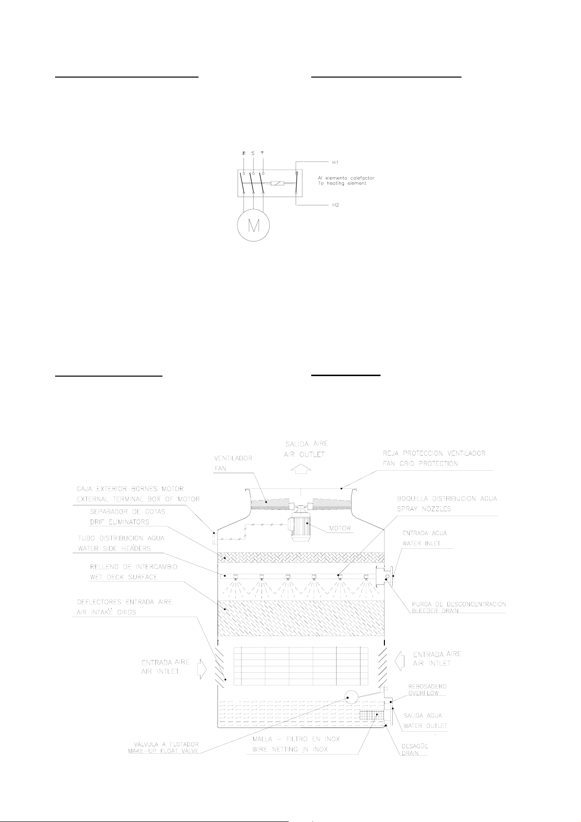
En las torres serie TVAP / TVAP-SPL la caja de bornes de los
motores se ha trasladado al exterior de la torre, lo que facilita
su conexión eléctrica. Para el conexionado deberán tenerse
presente las siguientes considera-ciones:
1. Para evitar condensaciones cuando el
motor está parado, las cajas de
bornes tienen dos terminales
suplementarios correspondientes a
las resistencias calefactoras. Éstas
deberán conectarse cuando
desconecta el motor
2. En los motores de arranque directo,
los puentes de conexión están
colocados en estrella o triángulo
según la tensión para la que se han
solicitado. En los motores para ser
conectados a un arrancador estrella-triangulo, los
puentes de conexión, colocados siempre en triángulo,
deberán eliminarse.
.
3. Cuando el motor eléctrico de la torre es accionado por un
cuadro eléctrico situado a distancia, es conveniente
instalar un interruptor manual en la proximidad de la
torre, que permita efectuar las operaciones de
manutención con absoluta seguridad.
En cualquier caso, todas las conexiones eléctricas deben
realizarse respetando la normativa vigente en la materia.
FUNCIONAMIENTO
In the TVAP / TVAP-SPL series towers, the terminal box for
the motors has been moved to the outside of the tower to
facilitate connection to the power supply. When making the
connection, the following considerations should be borne in
mind:
1. To avoid condensations when the
motor is stopped, the boxes of terminals
have two terminals supplementary
corresponding to the heating element.
These will be connected when it
disconnects the motor.
2. The connection points in the direct
starter motors are arranged in a star or
triangular pattern, depending on the
voltage for which they have been ordered.
The connector bridges, which are always
arranged in a triangular pattern, must be eliminated from
motors that are to be connected to a star-triangle starter
motor.
3. When the tower’s electric motor is operated by a remote
electric panel, it is advisable to install a manual switch
near the tower that will enable maintenance operations to
be carried out in complete safety.
In any event, all electrical connections must be made in
accordance with the relevant standards and regulations in
force at the time.
OPERATION
Es conocido que el funcionamiento de las torres de
refrigeración está basado en la evaporación de una parte del
agua recirculada por la torre, que al absorber calor en éste
fenómeno, enfría el resto del agua en circulación.
It is well known that the way cooling towers work is based on
the evaporation of part of the water which is recycled by the
tower. As heat is absorbed, the rest of the water in circulation
is cooled.
- 9 -
Page 10
Para facilitar la evaporación del agua, es necesario hacer
circular una corriente de aire que se mezcle lo más
íntimamente posible con el agua.
El proceso conlleva dos consecuencias importantes para el
normal funcionamiento de las torres:
1. Como consecuencia de la evaporación, la concentración
de sales disueltas en el agua aumenta progresivamente
durante el funcionamiento de la torre, produciendo
compuestos químicos alcalinos o ácidos que pueden
provocar incrustaciones o corrosión.
2. El aire que atraviesa la torre es lavado por el agua en
circulación dejando en suspensión o disolución todas las
impurezas contenidas en el mismo, tales como, humos,
vapores químicos, microorganismos, etc. que se
convertirán en lodos y soluciones corrosivas.
El mantener bajo control éstas concentraciones es el principal
objetivo de todo programa de mantenimiento
PRIMERA PUESTA EN MARCHA
Antes de la primera puesta en marcha de lar torres, efectuar
las operaciones siguientes:
1. Limpiar y en caso necesario lavar la bandeja de recogida
de agua eliminando todo tipo de suciedad.
2. Llenar de agua fría la bandeja hasta un nivel de 2/3 cm
por debajo del nivel del rebosadero.
3. Regular la válvula a flotador para que cierre al nivel
alcanzado en el punto anterior.
4. Poner en marcha las bombas de recirculac ión de agua y
ajustar el caudal hasta que el manómetro situada a la
entrada de la torre, señale la presión correspondiente a
las condiciones de trabajo.
5. A través de la puerta de inspección, controlar que todas
las boquillas tengan una distribución regular, eliminand o
si procede, las suciedades que pudieran haberse
arrastrado durante el proceso de instalación de las
tuberías.
6. Conectar al desagüe la válvula de desconcentración,
situada en la conexión de entrada de agua y regular el
caudal de purga en función de la calidad del agua de
aportación, siguiendo los consejos de los técnicos en
Tratamiento del Agua,
7. Hacer girar manualmente los ventiladores asegurándos e
de su libre rotación.
8. Poner en marcha los motores de los ventiladores y
verificar visualmente su correcto funcionamiento:
• Ausencia de ruidos anormales
• Ausencia de vibraciones
• Sentido de giro. El sentido de giro está marcado con
una flecha sobre el anillo del ventilador.
9. Controlar la tensión y la intensidad de las tres fases del
motor. La intensidad deberá ser inferior a la nominal del
motor, correspondiente a la tensión a que esté
conectado.
To facilitate evaporation of the water, it is necessary to
circulate an air current that mixes as closely as possible with
the water.
This process entails two major consequences for the normal
operation of the towers:
1. While the tower is operating, the concentration of salts
dissolved in the water gradually increases as a result of
the evaporation. This produces alkaline or acid chemical
compounds that can lead to scaling or corrosion.
2. The air going through the tower is washed by the
circulating water, leaving all the impurities in the air, such
as fumes, chemical vapours and microorganisms,
suspended or dissolved in the water, eventually forming
sludge and corrosive solutions
The main aim of the maintenance programme is to keep these
concentrations under control.
INITIAL START-UP
Before starting up the cooling towers for the first time, the
following operations must be carried out:
1. Clean and, if necessary, wash the sump to get rid of all
the dirt.
2. Fill the sump w ith cold water up to a level of between 2/3
cm beneath the level of the overflow.
3. Adjust the float valve so that it closes at the level reached
in point 2 above.
4. Start up the water recycling pumps and adjust the flow so
that the pressure gauge at the inlet to the tower shows
the stipulated pressure for normal operating conditions.
5. Through the inspection door, make sure th at the water is
distributed evenly by all the nozzles and eliminate, if
necessary, any dirt that has got in while the pipes were
being installed.
6. Connect to the drain the bleeder valve, located on hot
water inlet and regulate the flow of water in accordance
with the quality of the feedwater and the advice of the
water treatment experts.
7. Spin the fans round by hand to make sure that they rotate
freely.
8. Start up the fan motors and visually check that they are
working properly
Test the voltage and the intensity of the motor’s three phases.
The intensity should be less than the motor’s rated intensity,
corresponding to the voltage to which it is connected.
• No unusual noises.
• No vibrations
• Direction of rotation. The direction of rotation is
marked by an arrow on the fan ring
9. Test the voltage and the intensity of the motor’s three
phases. The intensity should be less than the motor’s
rated intensity, corresponding to the voltage to which it is
connected.
A LAS 24 HORAS DE FUNCIONAMIENTO:
Después de las primeras 24 horas de funcionamiento, y una
vez que la torre y las bombas hayan parado y vuelto a
arrancar:
1. Verificar la ausencia de ruidos anormales y de
vibraciones.
2. Inspeccionar el buen funcionamiento de las boquillas
rociadoras.
3. Controlar el nivel de agua en la bandeja y reajustar la
válvula a flotador si fuese necesario.
24 HOURS AFTER START-UP
After the tower has been running for 24 hours, stop the tower
and the pumps, start them up again and then:
1. Make sure that there are no unusual noises or vibrations.
2. Inspect the spray nozzles to check that they are working
properly.
3. Check the level of the water in the tray and readjust the
float valve if necessary
- 10 -
Page 11
MANTENIMIENTO
MAINTENANCE
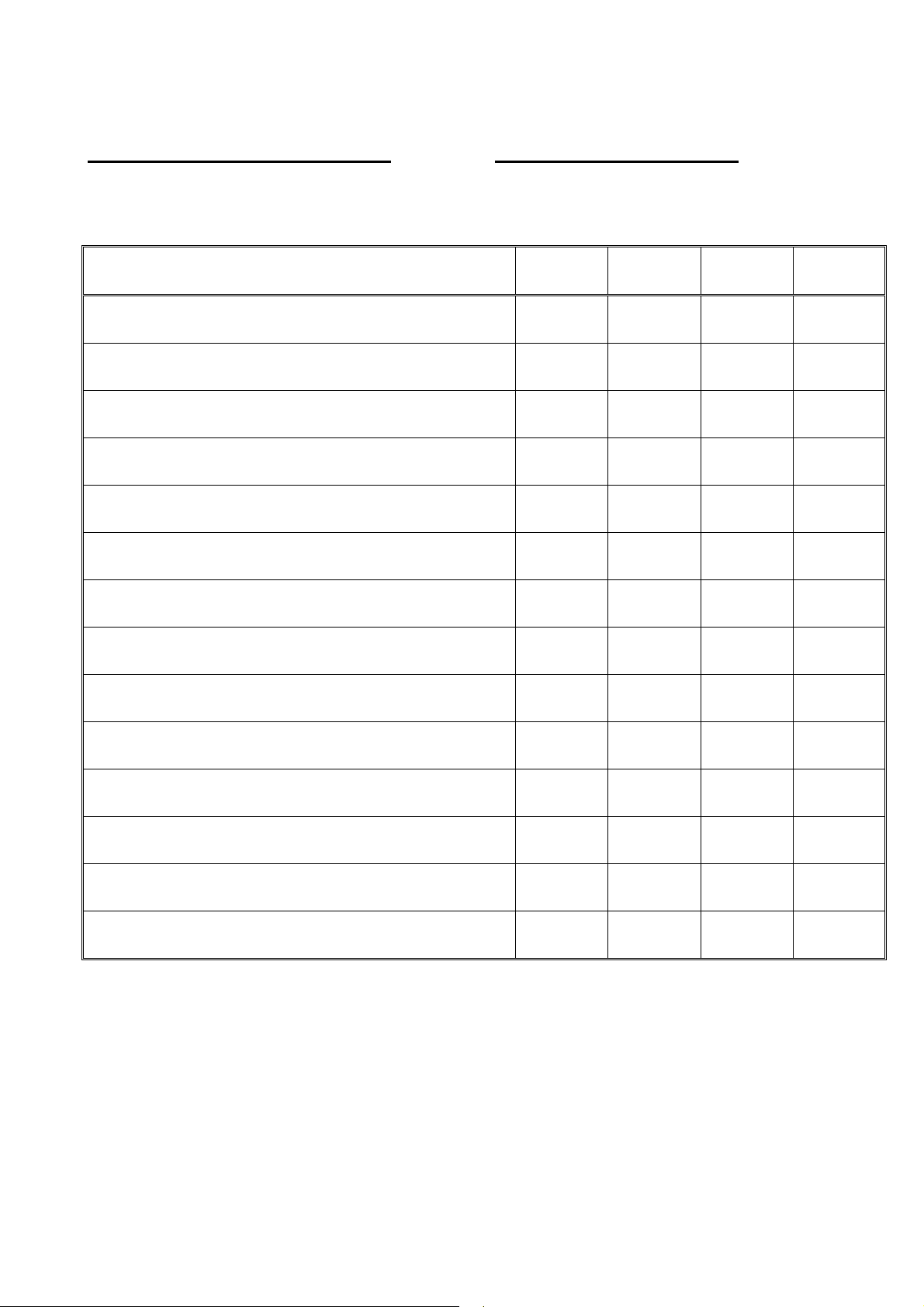
OPERACIONES DE MANTENIMIENTO
En la tabla siguiente se indican las operaciones que es
conveniente efectuar para mantener las torres en las mejores
condiciones de servicio.
Descripción de la operación
Descrption of service
Inspección general del aparato
Inspect general condition of unit
Limpieza y lavado de la bandeja
Cleaning and laundry of the basin
Limpieza del filtro
Cleaning sump strainer
Regular nivel de agua en la bandeja
Adjust sump water level
Comprobar funcionamiento válvula a flotador
Check make-up float valve
Revisar superficie del relleno
Inspect heat transfer section for fouling
Revisar boquillas y sistema de distribución de agua
Check spray nozzles and water distrib ution system
MAINTENANCE OPERATIONS
The following table shows the operations that it is advisable to
carry out in order to maintain the cooling towers in the best
working order.
Mensual
Monthly
Semestral
Semestral
Paro largo
Shut Down
(1)
Reinicio
Start-Up
Comprobar calidad del agua
Check water quality
Comprobar y regular consumo por purga de agua
Check and adjust bleed rate
Revisar separadores de gotas y su ajuste
Check and adjust drif eliminators
Vaciado de bandeja y circuito
Drain sump and piping
Comprobar ruidos y vibraciones anormales
Check unusual noise and vibrations
Comprobar consumo de los motores
Check motors current
Comprobar la libre rotación de los ventiladores
Check impeler for rotation without obstruction
(1) Para evitar la acumulac ión de agua estancada en la
balsa por efectos de la lluvia, dejar la conexión de
desagüe abierta durante las paradas estacionales o de
larga duración
(1) To prevent stagnant water from building up in the basin
as a result of rainfall, leave the drain open whenever the
towers are not in use for any appreciable length of time.
- 11 -
Page 12
PROCESOS DE MANTENIMIENTO
MAINTENANCE PROCESSES
En el diseño de las torres series TVAP / TVAP-SPL se ha
tenido como principal objetivo reducir los elementos que
requieren mantenimiento al mínimo. Por ello el empleo de
materiales no susceptibles a la corrosión, ausencia de
transmisión, etc. No obstante algunos elementos por su
normal funcionamiento o desgaste deberán ser revisados o
sustituidos con el tiempo.
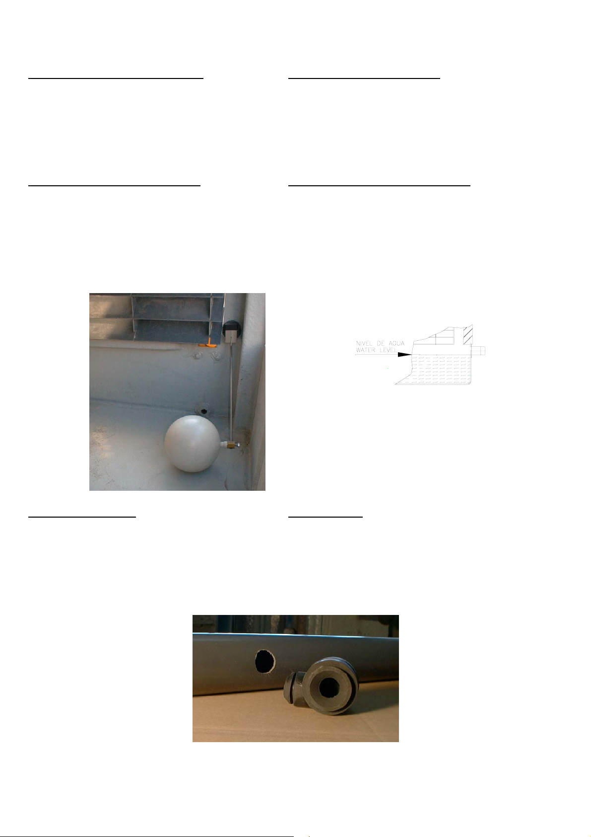
Válvula a flotador y nivel de agua
Su función es la de reponer intermitentemente el volumen de
agua que por efectos de la evaporación se pierde. Su
regulación se efectúa desplazando el flotador a lo largo del
vástago (Fig.: 4), hasta conseguir que cierre completamente
cuando el nivel de agua en la balsa se sitúe por la parte
inferior del tubo de rebosadero.(Fig.: 5) Si la válvula no cierra
por efectos de desgaste o rotura de la junta de cierre, será
necesario sustituirla.
The main objective in designing the TVAP / TVAP-SPL series
towers was to keep the elements requiring maintenance down
to an absolute minimum. That is why the materials employed
were chosen for their corrosion resistance, there are no
transmission mechanisms, etc. Never the less, some of the
parts will need to be serviced or replaced in time as a result of
wear and tear due to normal use.
Make-up float valve and water level
The float valve’s function is to replenish, or make up, from
time to time, the volume of water lost through evaporation. It
can be regulated by moving the float along the piston (Fig.. 4)
until the valve closes completely when the water level in the
basin falls below the overflow pipe.(Fig.: 5). If the valve fails to
close because the seal is worn or broken, it will have to be
replaced.
Fig.:4
Boquillas rociadoras
Las boquillas fabricadas en goma, están insertadas en los
tubos de distribución de agua por presión. (Ver Fig.: 6).
En la puesta en marcha inicial o con los años de
funcionamiento pueden haber acumulado suciedad
procedente de las tuberías, incrustaciones o envejecimiento,
ocasionando una deficiente distribución de agua. Será
necesario proceder a su limpieza o sustitución.
Fig.: 5
Spray Nozless
The rubber nozzles are snapped into the water side headers.
(See Fig.: 6)
When the tower is first started up, or after it has been
operating for some years, dirt from the pipes, scale or ageing
may build up in the nozzles so that they do not distribute the
water correctly. When this happens, clean them or replace
them.
Fig.: 6
- 12 -
Page 13
Para acceder a las boquillas en los modelos TVAP / TVAPSPL 008 al 078, será necesario separar la sección de
ventilación de la torre, situada por encima de la conexión de
entrada de agua.
En los modelos TVAP / TVAP-SPL 100 al 450 se puede
acceder a través de la puerta lateral, teniendo la preca ución
de no dañar la superficie del relleno de intercambio colocando
tarimas de madera u otro material.
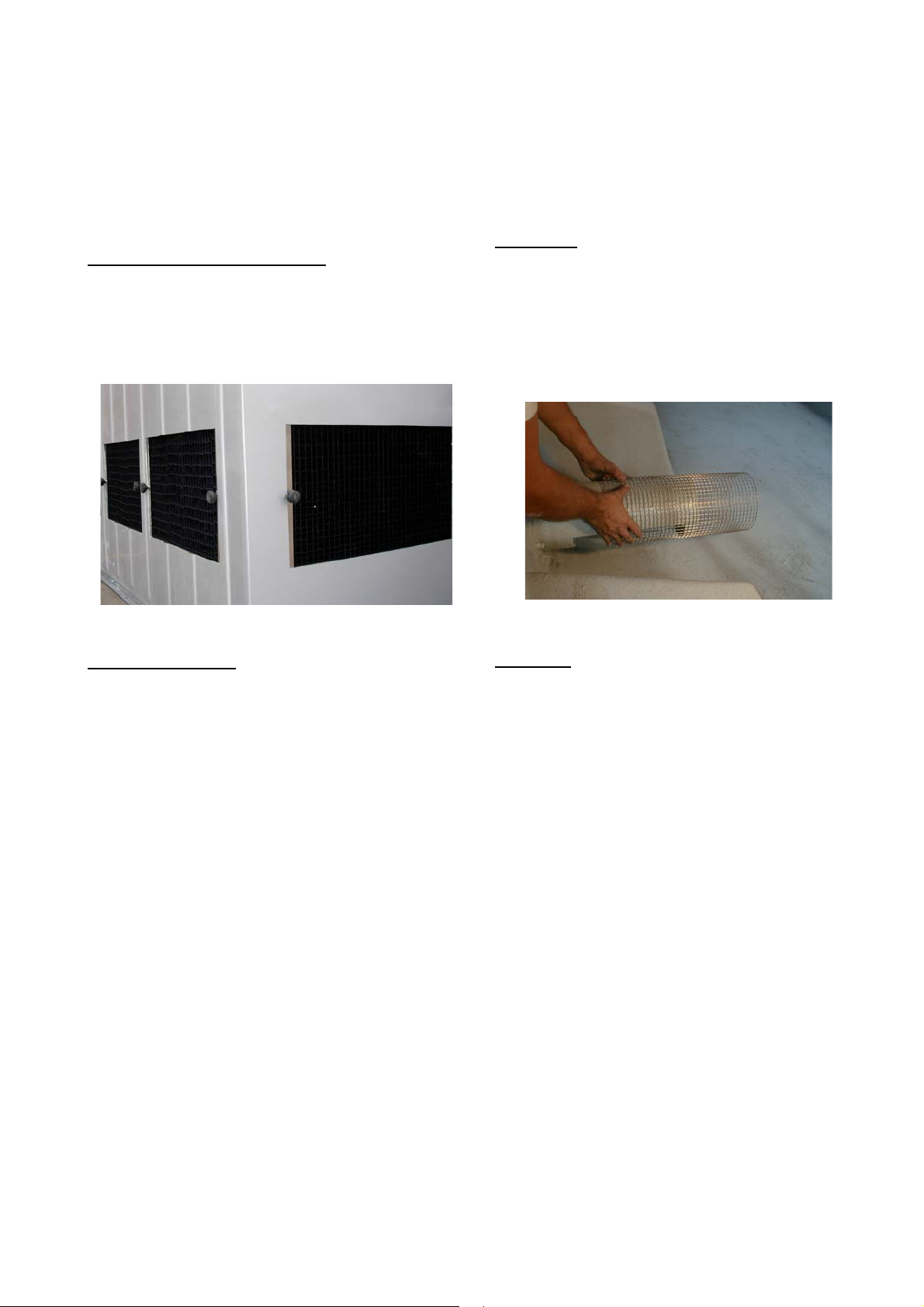
Filtro de aspiración de la bomba
Cada conexión de salida de agua a la bomba, está protegida
por un filtro de malla metálica en acero inoxidable.
Para su acceso y limpieza periódica, será necesario quitar
una de las rejas de entrada de aire (Fig.: 7), extrayendo el
filtro con gran facilidad. (Ver Fig.: 8)
To gain access to the nozzles in models TVAP / TVAP-SPL
008 to 078, you have to separate the ventilation section,
which is situated above the water inlet.
In the TVAp / TVAP-SPL 100 to 450 models, you can gain
access to the nozzles by the side door, but must be careful
not to damage the wet deck surface. Use platforms made of
wood or other suitable material as a precaution.
Outlet filter
Each connection through which water is pumped out of the
tower is protected by a stainless steel wire mesh filter.
For access and periodical cleaning, you have to separate one
of the air intake grilles(Fig.:7) and take the filter out. (See Fig.:
8)
Fig.: 7
Motor del ventilador
Todas las torres de la serie TVAP y TVAP-SPL tienen el
motor directamente acoplado al ventilador, sin ningún
mecanismo de transmisión, por lo que su mantenimiento
periódico prácticamente es nulo. No obstante es conveniente
revisarlo al menos una vez al año, eliminando las
incrustaciones o suciedad que pueda haberse depositado
sobre el exterior del mismo, lo que dificultaría su adecuada
refrigeración.
Todos los motores de las torres TGA son de tipo especial,
preparados expresamente para su funcionamiento en ésta
aplicación, por lo que no es aconsejable en caso de
sustitución, elegir cualquier motor standard.
Los cojinetes del motor son de tipo cerrado (2Z), de engrase
permanente. No obstante con los años de funcionamiento
tendrán un lógico desgaste y finalmente habrá que
sustituirlos. En éste caso deberán reponerse o mejor sustituir
las guarniciones de cierre situadas en el eje, y sellar
nuevamente los escudos al montaje
Fig.: 8
Fan motor
In all the series TVAP and TVAP-SPL towers, the motor is
directly connected to the fan, without any transmission
mechanism, virtually eliminating the need for periodical
maintenance altogether. Never the less, it is advisable to
service it at least once a year, getting rid of any scale or dirt
that has built up on the outside of the motor, as this could
hamper adequate cooling.
All the motors in the TVAP towers are of a special type
expressly prepared to operate in this application. If they ever
need replacing, it is therefore not advisable to choose a
standard motor.
The motor has permanently lubricated bush bearings (2Z).
Never the less, such bearings also gradually wear down over
the years and will eventually have to be replaced. When this
happens, the seal packing on the axle should also be
replaced and the shields re-sealed to the mounting.
- 13 -
Page 14

MANTENIMIENTO DEL AGUA
WATER MAINTENANCE
Aunque todos los elementos descritos que requieren
mantenimiento en las torres de refrigeración son importantes,
el más significativo de ellos es la propia agua que circula por
la torre.
Por el principio en que está basado el funcionamiento de l as
torres, ya descrito anteriormente, el agua que debe aportarse
necesariamente para compensar el gasto por la evaporación
parcial de la misma, cuando es de origen natural y no ha
sufrido ningún tratamiento previo de descalcificación u
ósmosis inversa, contiene diversas sales disueltas en
proporciones variables según sea su origen: Estas sales no
se evaporan y permanecen en el circuito provocando un
proceso de concentración progresiva hasta que rebas an los
límites de equilibrio y se precipitan formando incrustaciones
o, en otros casos, creando problemas de corrosión.
Incrustaciones y cómo evitarlas
El carbonato cálcico, una de las sales de calcio más
insoluble, es normalmente el principal responsable de las
incrustaciones en los circuitos de refrigeración. La
precipitación del carbonato cálcico tiene lugar cuando se
altera el equilibrio entre el bicarbonato cálcico y el gas
carbónico libre, ambos presentes en el agua de aportación.
En el circuito de refrigeración, la aireación del agua en la torre
provoca el arrastre a la atmósfera del gas carbónico,
originando rápidamente el desequilibrio causante de la
precipitación del carbonato cálcico.
La temperatura tiene también un pronunciado efecto sobre la
formación de las incrustaciones dado que la solubilidad del
carbonato cálcico es inversamente proporcional a la
temperatura.
La aportación de secuestrantes, dispersantes y compuestos
que inhiben la precipitación cristalina de las sales de calci o,
contenidos en los productos que se pueden dosificar al
circuito y un control estricto de las purgas, permiten
estabilizar las características del agua, evitando la formación
de incrustaciones.
La eliminación en el agua de aportación de las sales de calc io
y magnesio mediante un proceso de descalcificación o por
ósmosis inversa, también evitan el riesgo de incrustaciones,
aunque debe tenerse muy presente que las agua así
tratadas, normalmente, son de naturaleza fuertemente
corrosiva.
Otra forma de evitar las incrustaciones es la técnica llamada
“circuitos a pH controlado” que consiste básicamente en
mantener el pH del agua en un valor cercano a 7 por
dosificación automática de acido, con lo cual se
descomponen los carbonatos en forma de gas carbónico, que
se expulsa a la atmósfera en la torre. Las aguas así tratadas
también tienen naturaleza corrosiva.
Although all the elements in the cooling towers requiring
maintenance are important, the most important of all is the
water circulating round the tower.
The principle -already described above- on which the
operation of the towers is based means that the water which
has to be supplied to make up for that lost by evaporation will
contain various dissolved salts in variable proportions
depending on where it comes from, unless a deliming
treatment or reverse osmosis has been applied beforehand.
These salts do not evaporate. They remain in the circuit
becoming more and more concentrated until they exceed the
equilibrium limits and precipitate, in some cases forming
scale, in others causing corrosion problems.
Scale and how to prevent it
Calcium carbonate, one of the least soluble of calcium salts,
is normally the main agent responsible for scale in cooling
circuits. The precipitation of calcium carbonate occurs when
the balance between calcium bicarbonate and free carbonic
gas, both present in the feedwater, is upset.
In the cooling circuit, the aeration of the water in the tower has
the effect of removing carbonic gas into the atmosphere,
quickly leading to the imbalance that causes the calcium
carbonate to precipitate.
The temperature has a marked effect on the formation of
scale, as the solubility of calcium carbonate is inversely
proportional to the temperature.
Adding measured doses of sequestering agents, dispersing
agents and compounds that inhibit the crystalline precipitation
of calcium salts to the circuit and strictly controlling bleeding
can stabilise the characteristics of the water and prevent the
formation of scale.
Eliminating calcium and manganese salts from the feed water
by a process of deliming or reverse osmosis also forestalls
the risk of scale, although it should be borne in mind that
water treated in this way is normally highly corrosive.
Another way to prevent the build-up of scale is to employ the
so-called “controlled pH circuits” technique, which basically
consists in keeping the pH of the water at a value of 7 by
automatically adding measured amounts of acid. This breaks
down the carbonates into carbon gas, which is expelled into
the atmosphere in the tower. The water treated in this way is
also corrosive.
Corrosión y cómo evitarla
Aunque las torres de la serie TVAP están construidas con
materiales libres de corrosión, existen elementos metálicos
imprescindibles, tales como motores, soportes, etc., además
de las conducciones metálicas del circuito, que sí están
sometidas a procesos de corrosión.
El agente principal de la corrosión es el oxígeno disuelto en el
agua que por la aireación se aporta al circuito y los aniones
capaces de sulubilizar los metales, principalmente los
cloruros, sulfatos y nitratos. Las aguas que han sido tratadas
por ósmosis inversa y en general todas las agua poco
mineralizadas son potencialmente corrosivas.
Corrosion and how to prevent it
Although the TVAP series towers are built of corrosion-free
materials, they do have a certain number of essential metal
elements, such as motors, supports, etc, in addition to the
circuit’s metal piping, that are subject to corrosion processes.
The main corrosive agents are the oxygen dissolved in the
water that gets into the circuit through aeration and the anions
capable of solubilising metals, chiefly chlorides, sulphates and
nitrates. Water that has been delimed or treated by reverse
osmosis, and in general all low-mineral water, is potentially
corrosive.
- 14 -
Page 15

Las incrustaciones, los depósitos de lodos de origen
bacteriano recubren superficies donde la circulación del
líquido es inexistente, creándose zonas con distintas
concentraciones de oxígeno disuelto, lo que genera pil as de
corrosión galvánica.
Las soluciones disponibles para evitar los problemas de
corrosión, son los inhibidores de corrosión y de pares
galvánicos, asociados a dispersantes, que son sustancias
que protegen las superficies metálicas al formar un micro-film
aislante o por introducir iones metálicos que son prot ectores
catódicos.
Scale and sludge deposits of bacterial origin cover surfaces
where the liquid does not circulate at all, creating areas with
different concentrations of dissolved oxygen, which in turn
cause pitting.
The available solutions for preventing corrosion problems are
corrosion inhibitors and galvanic couples, in conjunction with
dispersing agents. These are substances that protect metal
surfaces by forming an insulating microfilm. An alternative
method is to introduce metal ions, which act as cathodic
protectors.
Lodos, microorganismos y su control
El medio ambiente y la contaminación atmosférica son las
principales causas de acumulación de lodos en el circuito.
Para el control de las materias en suspensión, la solución
más eficaz es la filtración de una fracción del caudal de ag ua
y la utilización de dispersantes orgánicos.
Los microorganismos también son introducidos en el circuito
a través del aire que atraviesa la torre. En el circuito se dan
condiciones muy favorables para su desarrollo al coincidir
una temperatura ideal con la presencia abundante de oxígeno
disuelto.
La solución más efectiva para controlar el desarrollo de
microorganismos es la aportación de productos bactericidas
orgánicos o halogenados, asociados a biodispersantes.
Condiciones óptimas de trabajo
Las condiciones óptimas de trabajo que garantizan el buen
funcionamiento ininterrumpido del sistema vienen definidas
por el empleo de aguas en equilibrio: El índice de estabilidad
desarrollado por Ryznar (IR), que considera también la
temperatura, permite distinguir entre el carácter corrosivo o
incrustante de un determinado tipo de agua.
Con IR entre 6 y 7 el agua se encuentra en equilibrio, ni
incrustante ni corrosiva. Valores inferiores indican tendencia
del agua a incrustar y valores superiores la vuelven corrosiva.
Controlling sludge and micro-organisms
The environment and atmospheric contamination are the
principal causes of sludge build-up in the circuit.
The most effective solution for controlling matter in
suspension is filtering a fraction of the water flow and using
organic dispersing agents.
Micro-organisms also enter the circuit via the air that passes
through the tower. The circuit provides favourable conditions
for them to develop, as it has an ideal temperature and an
abundant supply of dissolved oxygen.
The most effective solution for controlling the growth of microorganisms is the use of organic or halogenated bactericidal
products in conjunction with biodispersants.
Optimal operating conditions
Optimal operating conditions, i.e. those that ensure that the
system will operate correctly and uninterruptedly, are defined
by the use of water in equilibrium. The stability index
developed by Ryznar (RI), which also takes into account the
temperature, allows you to determine whether, and to what
extent, a particular type of water is corrosive or scale-forming.
With an RI between 6 and 7, the water is balanced, neither
scale-forming nor corrosive. Lower values indicate a tend ency
for the water to form scale, while higher values indicate that it
is corrosive.
Purga de desconcentración
Las torres de la serie TVAP, están dotadas con una válvula
de paso en cada conexión de entrada del agua caliente, que
deberá conectarse al desagüe, para efectuar una purga
constante del agua.
A falta de mayores conocimientos sobre la calidad del a gua
de aportación, es aconsejable purgar una cantidad de agua
equivalente al volumen evaporado, lo que mantendrá
aproximadamente dos ciclos de concentración en el agua del
circuito.
La cantidad de agua evaporada por una torre de refrigeración
viene dada por el consumo de calor necesario para evaporar
un litro. ( 560 Kcal. aprox.)
Kcal / h
Agua evaporada = ---------------
560
DATOS DE IDENTIFICACIÓN
Todas las torres de refrigeración serie TVAP, llevan
incorporada una placa metálica de identificación. Para
cualquier información sobre modelos concretos o para
solicitar recambios sobre las mismas, es indispensable
referirse al número de orden marcado en la placa.
Bleeder drain
The TVAP series towers have a flow valve on each inlet hot
water connection, that it will be connected to the drain, for
make a constant purge of the water.
Unless you have more detailed knowledge about the quality of
the feedwater suggesting otherwise, it is advisable to bleed an
amount of water equivalent to the volume evaporated, which
will keep approximately two cycles of concentration in the
circulating water.
The amount of water evaporated by a cooling tower is given
by the consumption of heat required to evaporate one litre
(approx. 560 Kcal)
Kcal/h
Evaporated water = --------------
560
IDENTIFICATION DETAILS
All the TVAP series cooling towers are fitted with a metal
identification plate. If you require any information about
particular models, or wish to order spare parts for them, you
must quote the serial number on the plate.
- 15 -
Page 16
- 16 -
Técnicas Evaporativas, S.L.
Plg. Ind. Can Humet – Pintor Joan Miró, 1
08213 – Polinyà (Barcelona)
Tel.: 937 133 573 Fax.: 937 133 160
 Loading...