

Page 1
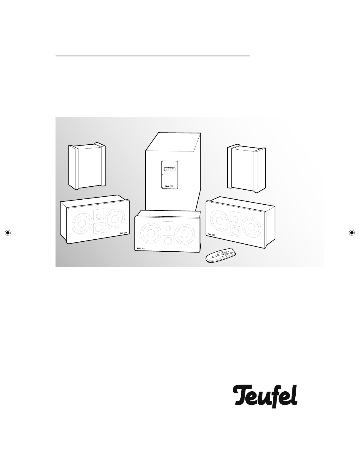
Technical Description and Operating Instructions
gb was
here
System 8
5.1 Home Theater Speaker Set with THX Ultra 2 Certifi cate
Page 2

Contents
General notes and information ......................................................................................................................................3
Notice .......................................................................................................................................................... 3
Trademarks .................................................................................................................................................. 3
Original packaging ........................................................................................................................................ 3
Complaints .................................................................................................................................................... 3
Contact ........................................................................................................................................................ 3
Proper use ..................................................................................................................................................... 3
Safety notes ..................................................................................................................................................................4
Overview ......................................................................................................................................................................5
Control elements and connections ..................................................................................................................................6
Remote control ..............................................................................................................................................................7
Inserting batteries .......................................................................................................................................... 7
Functionality .................................................................................................................................................. 7
Assembly ......................................................................................................................................................................7
Mounting the spikes ....................................................................................................................................... 7
Protective grid ............................................................................................................................................... 7
Setup ............................................................................................................................................................................8
Location tips .................................................................................................................................................. 8
Center speaker .............................................................................................................................................. 8
Front speaker ................................................................................................................................................ 8
Subwoofer .................................................................................................................................................... 8
Rear speakers ................................................................................................................................................ 8
Connecting ....................................................................................................................................................................9
Subwoofer .................................................................................................................................................... 9
Speaker ........................................................................................................................................................ 9
Connection to a power supply ....................................................................................................................... 10
Adjusting.....................................................................................................................................................................11
Adjustable AV receiver ..................................................................................................................................11
Non-adjustable AV receiver ...........................................................................................................................11
Operation ...................................................................................................................................................................12
Subwoofer ...................................................................................................................................................12
Activating and deactivating ...........................................................................................................................12
Care and cleaning .......................................................................................................................................................13
Troubleshooting ...........................................................................................................................................................14
Protecting the environment ..........................................................................................................................................15
Technical data .............................................................................................................................................................15
2 • System 8
Page 3
General notes and information
Notice
The information in this document may change without
prior notice and in no way constitutes any liability on the
part of Lautsprecher Teufel GmbH.
No part of these instructions may be reproduced in any
form or be broadcasted in any way electronically, mechanically, by photocopy or recording without the written
permission of Lautsprecher Teufel GmbH.
© Lautsprecher Teufel GmbH
Version 2.0
December 2011
Trademarks
® All trademarks are the property of their respective
owners.
Complaints
In case of complaint we will need the following information to process your enquiry:
1. Invoice number
Can be found on the sales slip (enclosed with the
product) or on the order confi rmation received as a PDF
document, e.g. 4322543
2. Serial number or batch number
Located on the back side of the unit,
e.g. serial number: S10....
Many thanks for your support!
Contact
For questions, suggestions or criticism please contact our
customer service department:
Lautsprecher Teufel GmbH
Gewerbehof Buelowbogen
Buelowstrasse 66
10783 Berlin (Germany)
Phone: 00800 - 200 300 40 (free of charge)
Fax: +49 (0)30 / 300 930 930
E-mail: [email protected]
www.teufelaudio.com
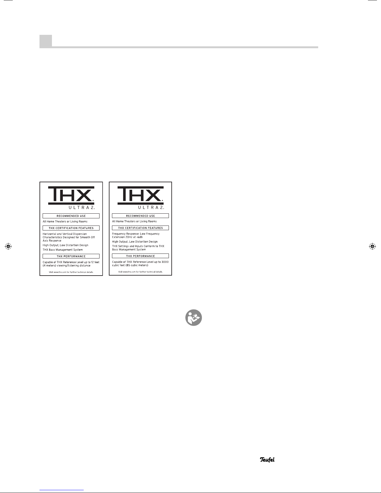
THX and the THX logo are trademarks of THX Ltd., which
are registered in some jurisdictions. All rights reserved.
Original packaging
If you wish to exercise your eight-week right of return, we
ask that you be absolutely sure to hold onto the packaging. We can only accept the return of the speakers WITH
THE ORIGINAL PACKAGING.
Empty boxes are not available!
Proper use
Only use the unit as described in these operating instructions. Any other use will be deemed as not in accordance
with the instructions and may lead to damage to property
or even persons.
The manufacturer accepts no liability for damage caused
by use not in accordance with the instructions.
The unit is intended for private use.
Before operating the unit for the fi rst time please
read the safety notes and operating instructions
carefully. This is the only way to use all functions
safely and reliably.
Keep the operating instructions safe and pass them on to
anyone who may own the unit after you.
• System 8 3
Page 4
Safety notes
Caution icons
You will fi nd the following caution icons in these instructions:
Danger
Attention
High risk !
Failure to observe the warning may result in
severe personal injury or death.
Moderate risk !
Failure to observe the warning may result in
p roperty damage.
Minor risk!
Points which should be observed when handling the unit.
Safety notes
Danger
electric shocks.
• The device is only suitable for use with a power supply
• If the unit’s case or mains cable is defective or shows
• If the unit emits smoke or smells of burning or other
• Never open the unit’s housing.
• Do not insert any objects through the vent slots in the
• Only use the unit in indoor areas.
• Do not operate the unit in damp areas and protect it
• Never touch the mains adapter with damp hands.
• Check the unit regularly for damage.
Risk of electric shock!
Faulty installation of electrical equipment or
mains voltage which is too high can cause
voltage of 230–V~/50 Hz.
other signs of visible damage, disconnect the mains
adapter immediately from the socket and do not operate the device.
unusual odours, disconnect it immediately from the
power supply and do not operate it.
Repairs may only be carried out by an authorised
specialist workshop. Only parts which conform with the
original unit specifi cations may be used in this case.
There are electrical and mechanical parts in this unit
which are necessary in order to avoid exposure to
sources of danger.
housing.
from drops of water or splash water.
Also take care not to stand vases or other containers
fi lled with liquid on or near the speaker in order to
avoid liquid getting into the case. If water or other
eign objects penetrate the case, immediately disconnect
the power plug and if applicable, remove any batteries.
Send the unit to our service address in this case.
for-
Danger
• Do not allow children to play with the unit or the pack-
• Ensure that children do not remove small parts from
produced when the subwoofer is set to full volume once
activated. This may have psychological consequences
and also cause physical injury. Children and pets are
particularly at risk.
• Set your signal source unit volume control to a low
• When the volume is set high, always keep a certain
• To avoid damage to health, avoid extended listening at
Danger
• Do not allow battery acid to come into contact with
Danger
• Never use the units unmounted in vehicles, in unstable
• Arrange the speakers so that they cannot be knocked
• If mounting the speakers on the wall, make sure that
• Only use suitable wall holders to mount the speakers.
• Do not place the unit near sources of heat (e.g. heat-
Danger to children!
Children can become trapped in the packing
fi lm when playing and suffocate.
ing fi lm. Danger of suffocation.
the unit or take them off of the unit (e.g. control knobs
or plug adapters). They could swallow the parts and
choke.
Never allow children to operate electrical devices
unsupervised.
Danger to hearing!
Loud noise may lead to hearing loss.
Very high noise pressure may be suddenly
setting.
distance from the unit and never place your ear directly
on the speaker.
high volume.
Danger of chemical burns!
Leaking battery acid may lead to chemical
burns.
skin, eyes and mucus membranes. In case of contact
with acid rinse the affected location immediately with
plenty of plain water and if necessary see a doctor.
Danger of injury/damage!
Incorrect location may result in damage.
locations, on wobbly tripods or furniture, on insuffi ciently dimensioned brackets etc. The speakers could
tip or fall down and cause injury to persons or be
damaged.
over accidentally and make sure that the cables do not
pose a trip hazard.
the installation is carried out expertly.
Verify the carrying capacity of the walls.
ers, ovens, other heat generating equipment such as
amplifi ers etc.)
4 • System 8
Page 5
Attention
• Do not place open fl ames such as burning candles or
• Ensure suffi cient ventilation.
• Do not place the unit in direct sunlight.
• Do not cover the ventilation slots with curtains, cloths,
Fire hazard!
Improper use may lead to damage or fi re.
similar on the unit.
newspapers or similar. Heat build-up inside the unit
can shorten the lifetime of the unit.
Overview
햲
Attention
• If the unit is to be left unsupervised for a long period
Risk of damage!
Power overload due to lightning strike may
damage or destroy the unit.
(e.g. during a holiday), or if a thunderstorm is forecast,
disconnect it from the mains power supply.
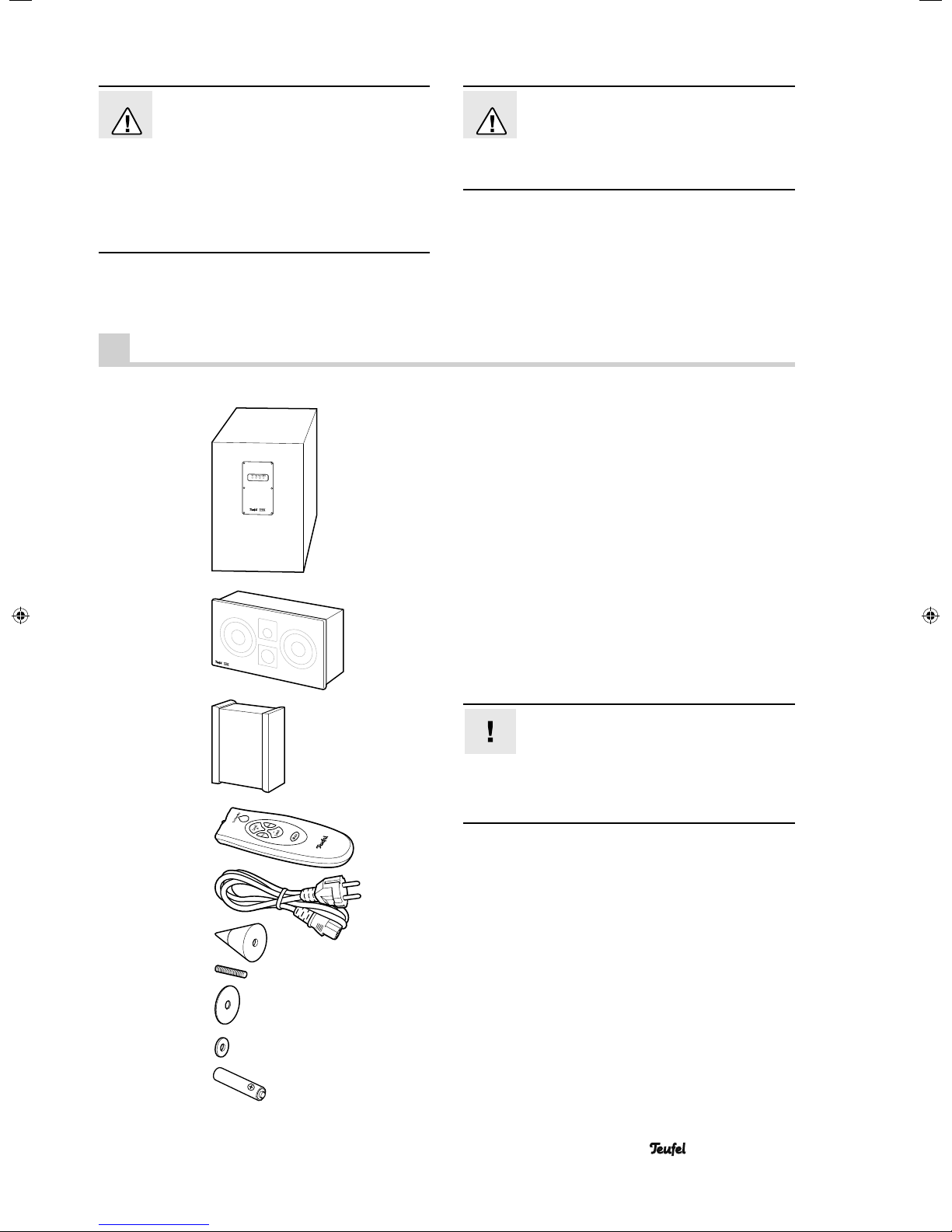
Product contents of the 5.1 Cinema Set*
햲 1 x S 8000 SW active subwoofer
햳 3 x S 800 FCR front speakers
햴 2 x S 800 D dipole rear speakers
햵 1 x remote control
햶 1 x power cord for the subwoofer
햷 4 x spikes for the subwoofer
햸 4 x threaded bolts
햹 4 x plastic discs
햺 4 x washers
햻 2 x batteries for remote control (type AAA)
햳
햴
햵
햶
햷
햸
햹
햺
햻
* The Concert Set 5.1 does not contain any two
separate dipole rear speakers, but fi ve identical front
speakers.
Connector cables
System 8 is delivered without connector
cables due to the variety of different customer
needs. You can fi nd suitable cables in our webshop
(www.teufelaudio.com) in the “Accessories” area. You
can also purchase speaker stands and wall brackets
for the speakers there.
Check to be sure
• Check that all items have been delivered and that nothing is damaged.
• If the delivery is incomplete or you fi nd damage sustained in transit, do not operate the unit but contact our
service department (see page 3).
• System 8 5
Page 6
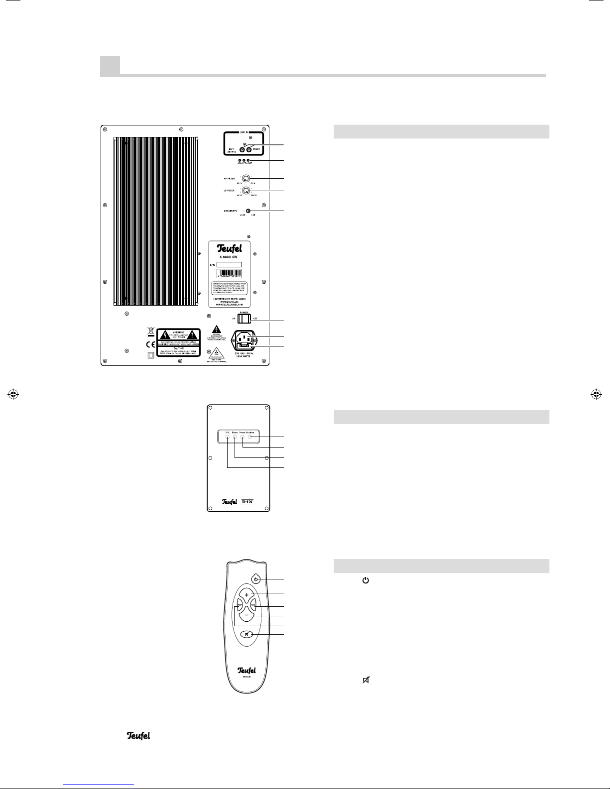
Control elements and connections
Subwoofer backside
1
2
3
4
5
6
7
8
Item Name Description
1Line In Audio input jacks
2 On • Off • Clip Power LEDs
On: Subwoofer on
Off: Subwoofer off/overloaded
Clip blinks: Input is overloaded
Clip illuminated: Speaker protective circuit has been triggered
3HP FILTER High pass fi lter
4LP FILTER Low pass fi lter
5SENSITIVITY Sensitivity
6
7
8
POWER
–
–
Mains switch
Connector jack for power cord
Mains fuse
햶
Subwoofer front side
Remote control
10
11
12
13
14
15
16
17
18
Item Name Description
Receiver
9
9
10 Power Power LED: Red = Standby,
11 P h a s e
12 T H X
Item Name Description
13
14 +
15 Phase
16 –
17 T HX
18
®
Infrared receiver for remote
control
Green = Operation
Green = Phase shifting active
Red = Volume corresponds to
THX requirements
Turn the subwoofer on or to
standby
Increase subwoofer volume
Activate/deactivate phase shift-
ing (180°)
Reduce subwoofer volume
Set the subwoofer volume to the
THX level
Mute the speakers
6 • System 8
Page 7
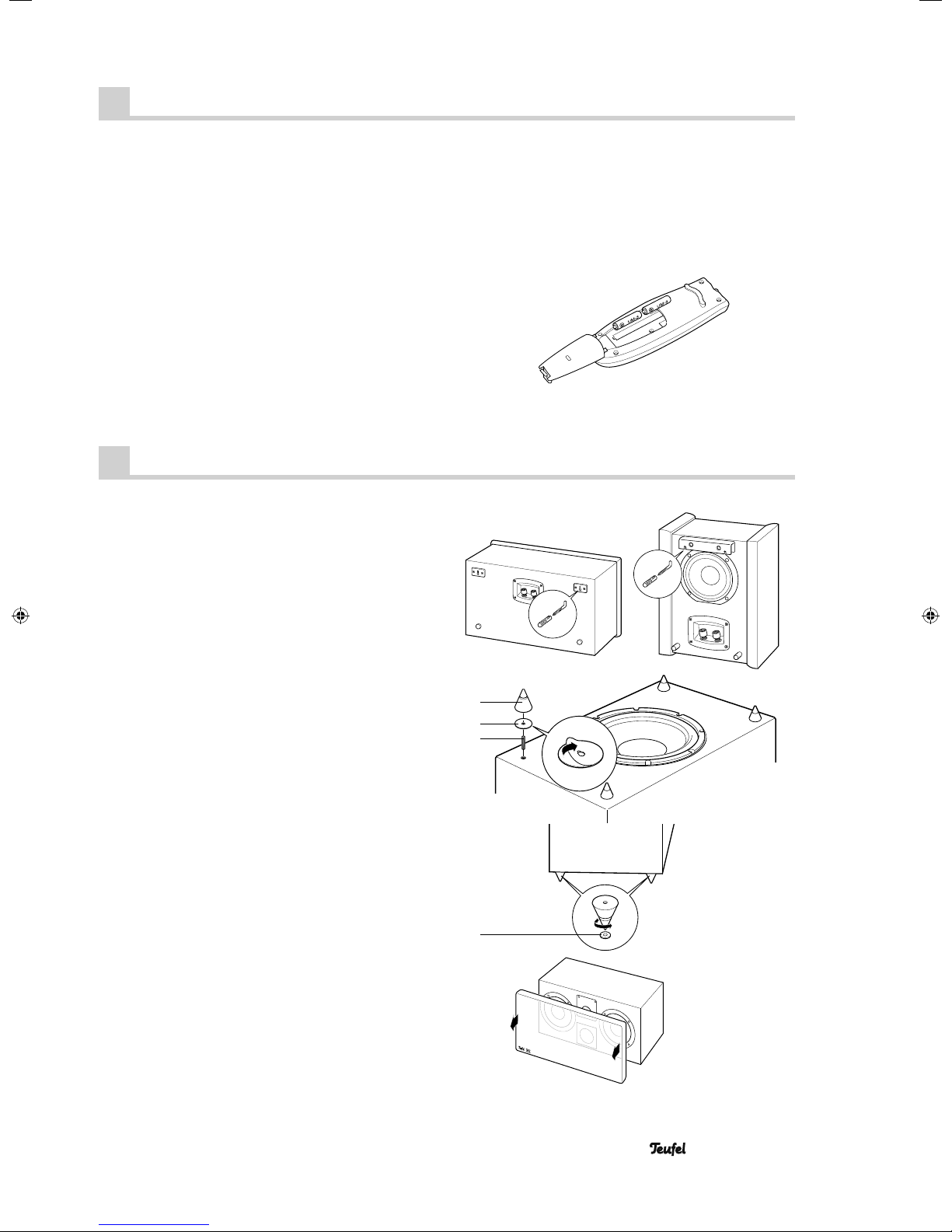
Remote control
You will need two micro-type or AAA batteries with 1.5
Volt (included in the product contents) in order to operate
the remote control.
Inserting batteries
• Push the small lever on the cover of the battery compartment on the back of the remote control and remove
the lid by lifting it off upwards.
• If applicable, remove any old batteries (please observe
the notes on page 14).
• Insert the batteries in the battery compartment as
shown in the fi gure.
• Place the cover back on the compartment and push it
closed.
Assembly
The brackets on the back side are intended for wall
mounting of the satellite speakers, whereas threaded
holes are located on the underside for assembly on a
speaker stand. You can purchase installation materials
(cables, speaker stands, wall brackets and resonance
dampers) especially tailored to these speakers in our
webshop (www.teufelaudio.com) in the “Accessories”
area.
Functionality
The remote control relays the control signals by means
of infrared light. For this, you must point the front of the
remote control towards the receiver. Make sure that the
infrared light is not obstructed by objects.
Mounting the spikes
The spikes ensure that the subwoofer has a stable position, they also minimise vibrations and provide enough
space to the fl oor for the subwoofer speaker.
• Carefully turn the subwoofer over and place it on a
soft, padded base.
• Screw a threaded bolt 햸 into the spike 햷.
• Remove the protective foil from a plastic disc 햹 and
slide it over the threaded bolt onto the spike.
• Screw the spike into one of the four threaded holes on
the bottom side of the subwoofer.
• For soft fl oors (e. g. carpet fl oor), you should place a
washer 햺 under each spike.
• The tips of the spikes may protrude somewhat in order
to compensate for irregularities in the fl oor.
Protective grid
The protective grids protect the sensitive speaker diaphragms and do not affect the sound. Depending on your
taste, you can easily pull off the grids to the front and
attach them again in the same manner.
햷
햹
햸
햺
• System 8 7
Page 8
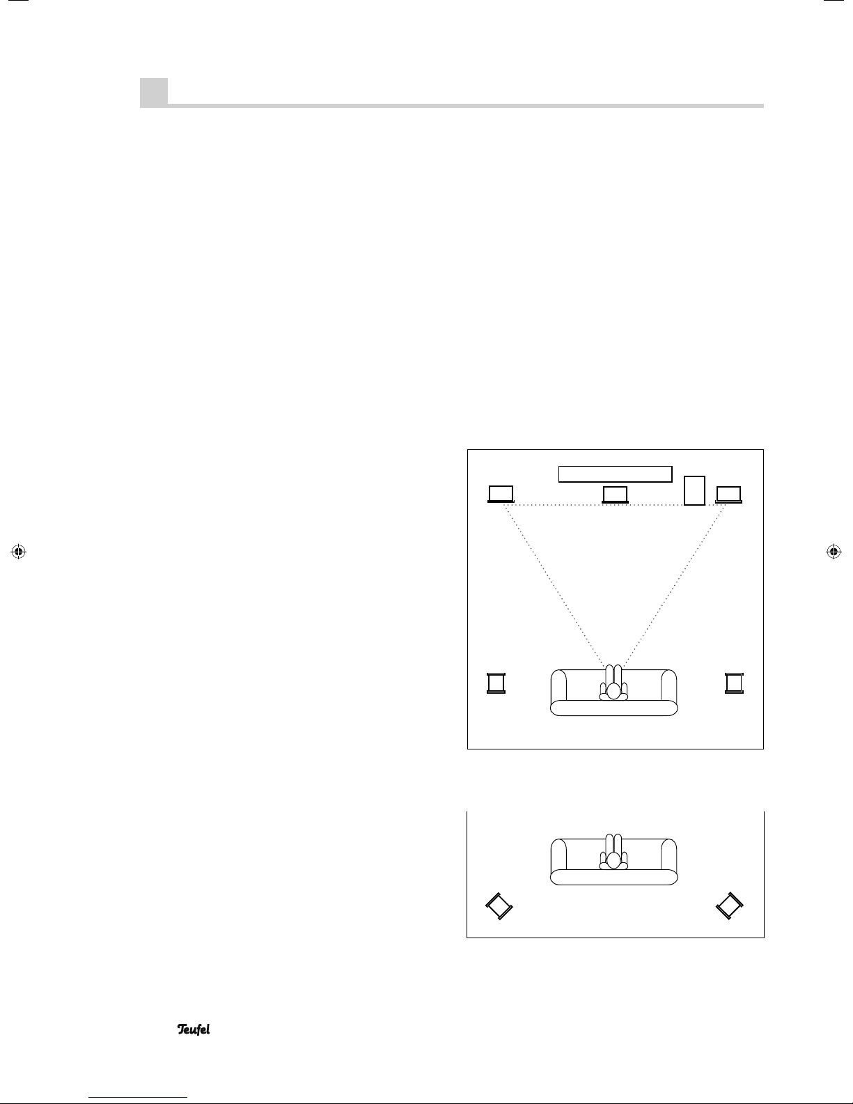
Setup
Location tips
• Select a stable, level base.
• Make sure that the environment is clean and free from
dust.
• Avoid placing the unit close to sources of heat or in
direct sunlight.
• Do not place any heavy objects on the cables or the
speakers.
The following data concern an “ideal home cinema“, in
which the viewer or listener sits in a central position at a
suffi cient distance in front of the television or screen (see
the adjacent graphic) and no objects (tables or the like)
are located in between. Unfortunately, the room, furnishings or one’s partner do not always allow for optimum
arrangement.
Modern AV receivers offer a variety of possibilities for
electronically compensating losses associated with the
arrangement. The following general rule applies: You can
always experiment on what works best in your listening
room in terms of sound and appearance based on our
recommendations. Let your ears (and eyes) be the judge!
Center speaker
Place one of the three front speakers 햳 in a central position, directly under the screen or silver screen.
TV
Front FrontCenter
Subwoofer
Front speaker
The two remaining front speakers 햳 are set up or hung
to the right and left of the screen at a height of approx.
40 to 120 cm. They should be in line with the center
speaker and form an equilateral triangle with the listener
– the so-called stereo triangle (distance from the listener
= distance between the speakers). The speakers should
project sound directly into the room or slightly towards
the listener.
Subwoofer
You should also place the subwoofer on the fl oor close
to the television A location between the front speakers is
ideal.
Rear speakers
The two rear speakers 햴 project sound to the front and
backwards. They are set up or hung to the side of the
listener at head level (140 to 210 cm). The distance to the
rear wall should be no less than 10 cm.
You can also set up the rear speakers somewhat behind
the listener at a height of 140 to 210 cm and turn them
within an angle of 45 degrees. As a result, the speakers
project sound against the walls and generate the desired
diffusivity.
Rear
Rear
Stereo triangle
Rear
Rear
8 • System 8
Page 9
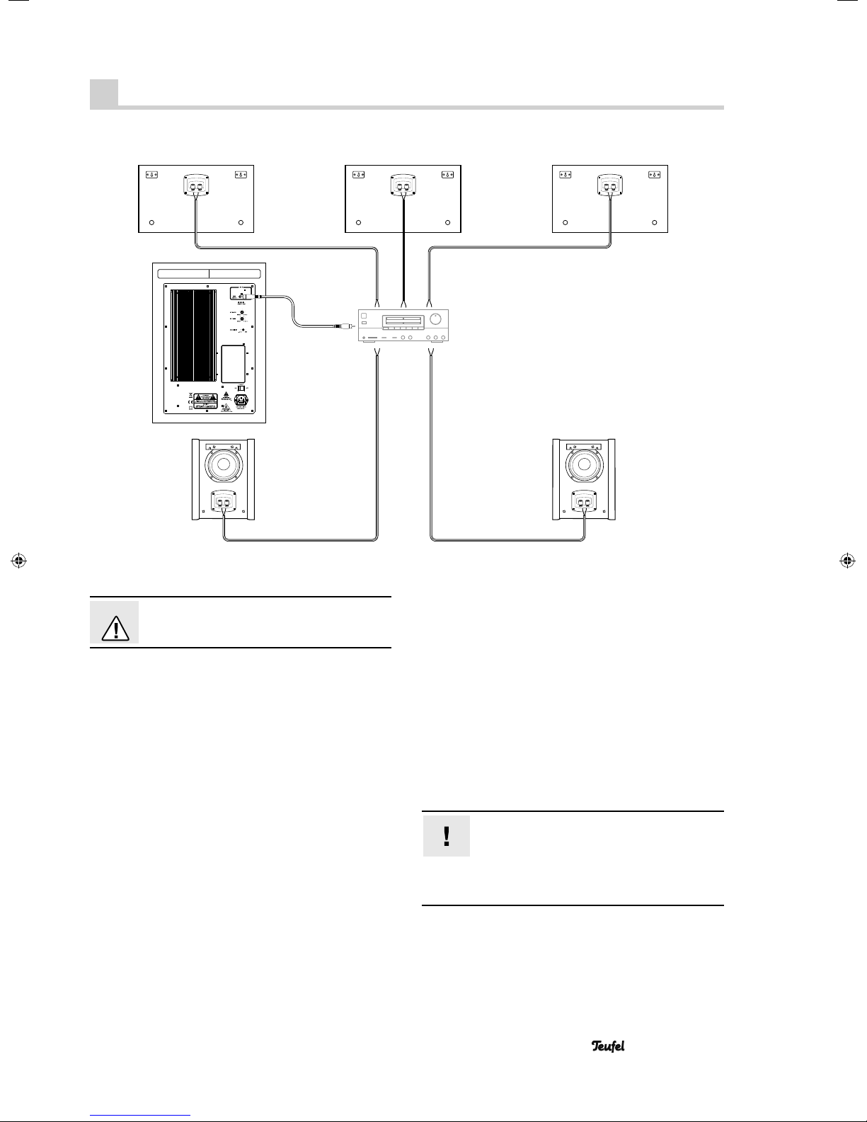
Connecting
Front left Front right
Subwoofer
Rear left Rear right
Center
AV receiver
Danger
• Pull the mains plug of your AV receiver out of the
Subwoofer
Ideally, the subwoofer is connected to the subwoofer jack
of the AV receiver with a mono RCA cable.
Normally, only the RCA jack 1
back side of the subwoofer is used for this purpose.
The RCA jack 1
Y adapter for the connection. This increases the subwoofer level slightly.
You will fi nd more information on this in the operating
instructions of your receiver.
If your receiver does not have a connection for a subwoofer, connect an available speaker outlet with an RCA
jack 1 of the subwoofer using a voltage reducer and an
RCA cable. We offer voltage reducers on our website in
the “Accessories” area.
Danger of injury/damage!
Arrange the cables so that they do not pose a
trip hazard.
socket to prevent accidental activation.
“LEFT MONO”
“RIGHT” is only occupied if you use a
on the
Speaker
• Lay the speaker cables from your AV receiver to each
of the speakers. These cables should be high-quality
double-wire speaker cable with marked strands. The
diameter should amount to at least 2.5 mm2.
Small tip: Label the cables on the receiver side –
this will help when taking down and setting up the
receiver.
• A connector terminal with two terminal clips is located
on the back side of each speaker. Here you can connect the speaker cables directly or with pin plugs. We
only describe the direct connection in these instructions.
• The terminal clips are each marked red (+) and black (-).
Make sure that the polarity is correct!
Connect the like-coloured terminal clips with
one another. Otherwise the sound quality will
suffer. The speaker connectors of your AV receiver
should have similar markings. The strands of the speaker cables are marked with different colours or shapes.
• System 8 9
Page 10
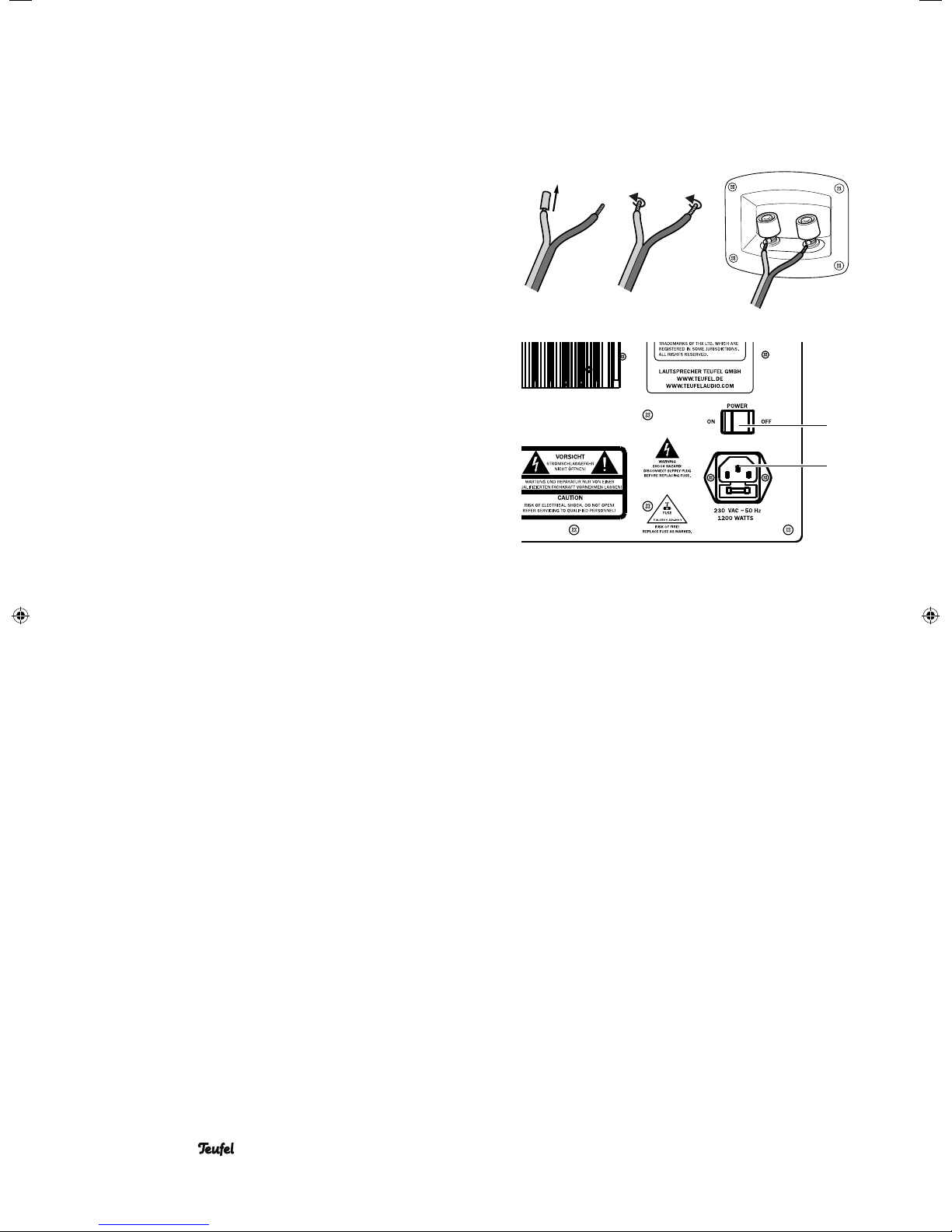
1. Split the single wire down to approx. 30 mm on both
ends and strip approx. 10 mm of insulation off of each
cord. Twist the single wire together so that no strands are
protruding.
2. Turn the connector terminal counterclockwise until
loose. Run the stripped cable end into the now visible
hole. Close the terminal by turning it counterclockwise.
The cable has now been clamped in place.
3. Connect all cables to the speakers this way.
4. Connect the speaker cables to your AV receiver. The
operating instructions of the appliance should contain
notes on this.
Connection to a power supply
1. Ensure that the mains switch 6 “Power” on the subwoofer is switched off (“0 OFF” position).
2. Connect the mains connector jack 7 with a mains
socket using the mains cord 햶.
3. Also plug the mains plug of your AV receiver back into
the socket.
6
7
10 • System 8
Page 11
Adjusting
Adjustable AV receiver
Most AV receivers feature a menu with speaker settings
(referred to as “Speaker Setup” or similar). In this case,
the following settings should be made:
• Size of the front, center and rear speakers to “normal”
or “small” – not “large”
• “Subwoofer” to “on”
• Crossover frequency for subwoofer to 80 Hz
• Subwoofer volume to more than 75 %
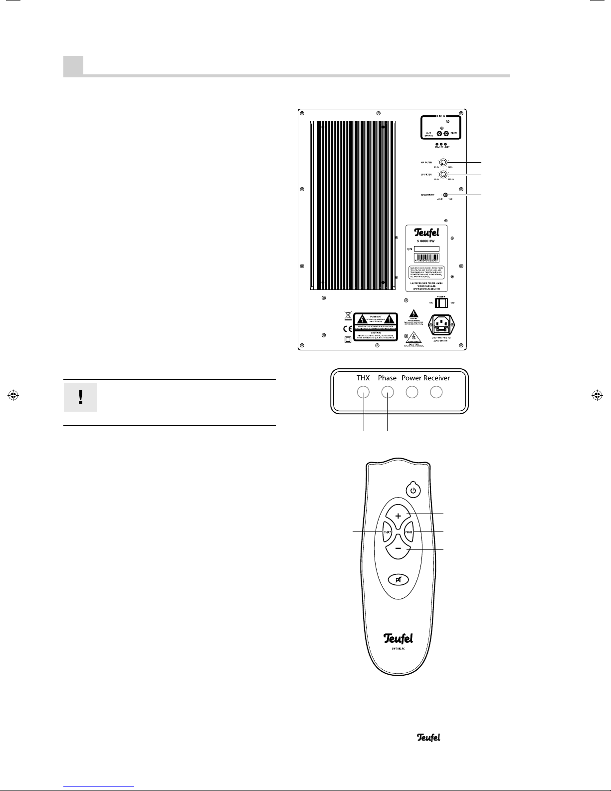
Set the subwoofer volume to the THX level. For this, push
the button 17 “THX” on the remote control while the subwoofer is on. The display 12 “THX” illuminates in red.
These settings will ensure that the speakers are used
optimally and you can make the fi nal fi ne tuning via the
automatic calibration function or the menu of your AV
receiver.
Non-adjustable AV receiver
If your AV receiver does not provide the above options,
you can make the most important settings directly on the
subwoofer. To do so, you will need a CD or DVD with
adequate, powerful sound.
Note:
The setting elements on the back side of the
subwoofer only work when THX mode is turned
off (the display 12 “THX” then turns green).
• Set the separation frequency with the control 4 “LP
FILTER” to approx. 80 Hz (second dash). This way, you
specify that the subwoofer only plays sounds up to this
frequency (adjustment range: 60–220 Hz).
• With the control 3 “HP FILTER” you can block low
frequencies (adjustment range: 20–60 Hz).
• With the switch 5 “SENSITIVITY”, soft signal sources
can be amplifi ed by 10 dB (switch setting: left).
• Once you have set the best sound, switch phase shifting
on and off several times with the button 15 “Phase”
(display 11 “Phase” is green). Then select the setting
at which the subwoofer sounds as loud and precise as
possible.
• Optimise the settings with other CDs/DVDs and different volumes.
17
3
4
5
12 11
14
15
16
Ideally, you will hear the system with a volume of 80–85
dB SPL. As a result, quiet passages will still be audible
and loud passages will not be detrimental to hearing. At
best, you should use a sound lever meter for determining
the volume, which you can purchase in our webshop.
• System 8 11
Page 12
Operation
Subwoofer
Activating and deactivating
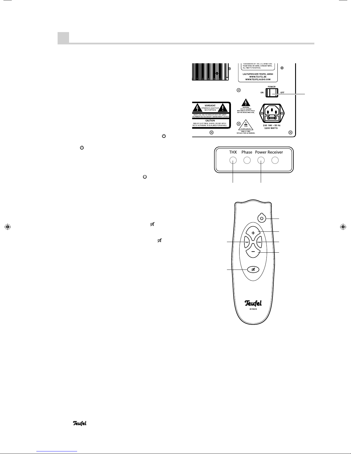
• With the switch 6 “Power” you can turn the power sup-
ply voltage on or off. After turning on, the subwoofer is
in standby and the power LED 10 “Power” is illuminated in red. If the subwoofer is on, the power LED 10
“Power” will be illuminated in green.
You can control all other functions with the remote control:
• Switch on and to standby: Push the button 13 “ ”.
Note: If the subwoofer is not deactivated with the button 13 “ ”, it will automatically switch to
audio signal is present for 20 minutes. As soon as an
audio signal is sent, the subwoofer will automatically
activate for music playback.
You can exit this auto-on mode by switching the subwoofer to standby with the button
• Increase the volume: Push the button 14 “+”.
• Decrease the volume: Push the button 16 “–”.
standby if no
13 “ ”.
6
1012
• Set the volume to THX level: Push the button 17 “THX”,
the display 12 “THX” is illuminated in red.
• Mute the subwoofer: Push the button 18 “
power LED 10 “Power” fl ashes in green.
• Turn the sound back on: Push the button 18 “
or adjust the volume.
”. The
” again
17
18
13
14
15
16
12 • System 8
Page 13
Care and cleaning
Clean the subwoofer and satellite speakers regularly with
a soft, damp microfi bre cloth. When doing so, please be
absolutely sure to observe the following instructions:
Danger
• Make sure that no liquid penetrates the unit.
• Disconnect the mains plug before cleaning.
Risk of electric shock!
In contact with live parts, water can lead to
electric shock or short circuit.
Attention
• If possible, only use plain water without any additives.
• In no circumstances should caustic cleaning products,
Risk of damage!
Using the wrong cleaning materials may damage the delicate surface of the case.
In case of stubborn marks, a mild soap solution may
be used.
white spirit, thinners, petrol or similar be used for
cleaning.
• System 8 13
Page 14
Troubleshooting
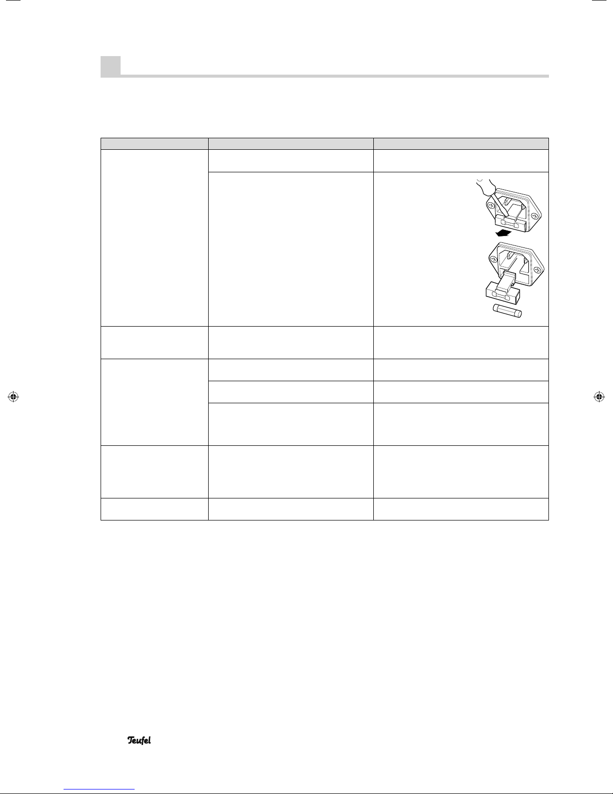
The following advice should help you to solve problems. If this doesn’t work, the extensive FAQs on our website will surely provide you with support. Otherwise, please contact our hotline (see page 3). Take note of the warranty instructions.
Problem Possible cause Solution
The subwoofer isn’t active,
the operation display 10 is
not on.
The subwoofer is off or doesn’t have any
power.
Fuse is defective. Replace the fuse:
Activate the switch 6 (“On I”). Check the
power cord and socket.
Disconnect the power
cord. Carefully pull the
fuse holder 7 on the mains
connection jack 8 out.
Push the old fuse down
and out. If applicable,
insert a new fuse (2 A
time-delay), close the
holder.
The subwoofer is not
working, but the operation
display 10 is on.
The subwoofer hums. The subwoofer is connected to another
Playback is noisy. Generally speaking, System 8 is very low-
The sound seems dull. A satellite has been connected with incor-
The volume has been set too low.
circuit than the rest of the system.
The buzzing is caused by problems with
the power supply.
The buzzing is caused by a multiple
socket.
noise. In most cases, the speaker system
with exceptional resolution in the high
range area can expose the poor quality of
a signal source (e.g. from MP3 fi les).
rect polarity.
Increase the volume with the button 14.
Connect the subwoofer and AV receiver to
the same circuit.
Buy a line fi lter and connect both devices to
it.
Use another multi-outlet power strip or connect the subwoofer directly to the wall socket.
It may also help to insert the power plug the
other way around.
Ensure that the source is sending a clear
signal.
Make sure the speaker cables of all satellites
are connected properly.
14 • System 8
Page 15
Protecting the environment
Disposal of the unit
Used units must not be disposed of with household waste!
If the unit is no longer operational, every
consumer is required by law to dispose of used
devices separately from household waste,
e.g. at a collection point run by the communal authority
borough. In this way it is ensured, that used devices are
properly recycled and that negative consequences on the
environment are avoided.
For this reason, electrical equipment is labelled with the
displayed symbol.
Batteries and rechargeable batteries
Batteries and rechargeable batteries must not
be disposed of with household waste!
Every consumer is required by law to bring all
batteries and rechargeable batteries, whether
they contain harmful substances*) or not, to a collection
point run by the communal authority or borough or run
commercially, so that they can be disposed of in an environmentally friendly manner.
Please only hand in fully discharged batteries and rechargeable batteries !
*) labelled with: Cd = Cad mi um, Hg = Mercury , Pb =
Lead
Technical data
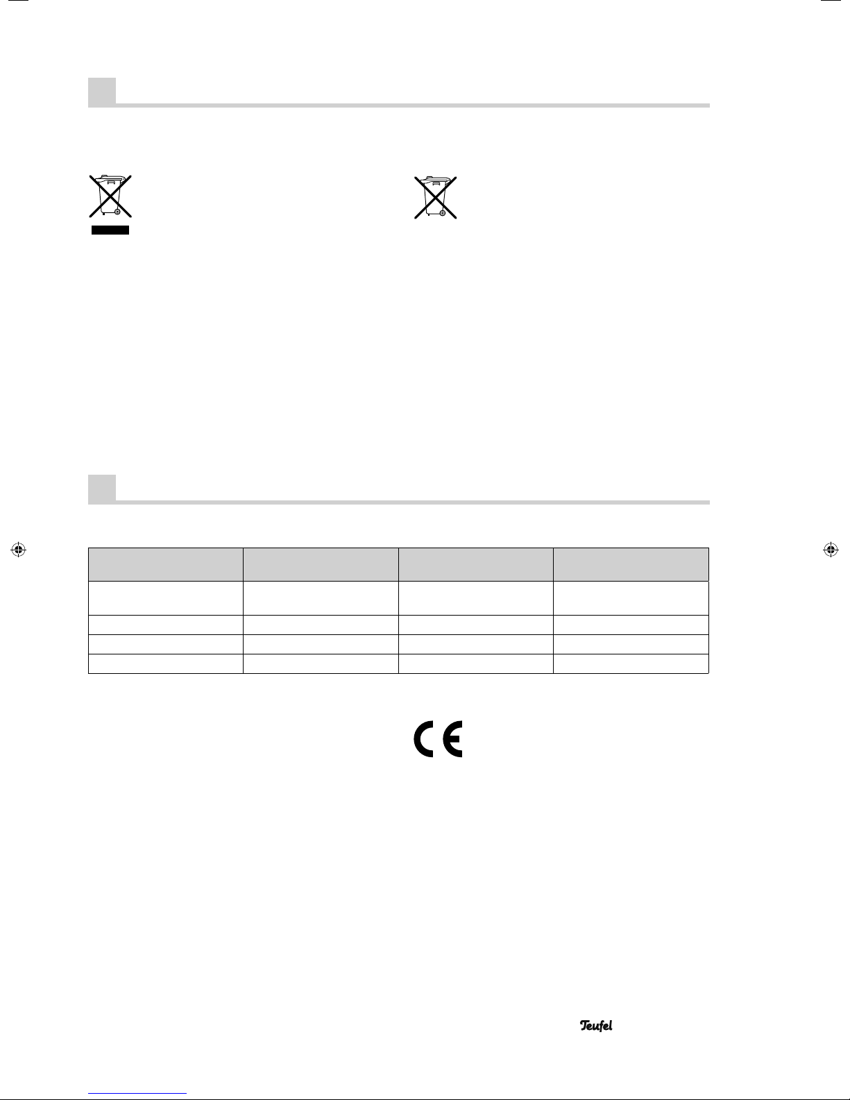
S 8000 SW
active subwoofer
Dimensions (WxHxD) 360 x 700 x 557 mm
(with spikes)
Weight 41.7 kg 8.5 kg 6.1 kg
Operating voltage 230 V~/50 Hz – –
Max. power consumption 1200 watts – –
S 800 FCR
front speakers
460 x 200 x 250 mm 238 x 172 x 308 mm
S 800 D
dipole rear speakers
For further technical information, please view the product
description on our website at www.teufelaudio.com.
Technical changes reserved!
This product conforms with Council of the
European Union guidelines 2004/108/EC and
2006/95/EC.
• System 8 15
Page 16

For questions, suggestions or other issues please contact our customer service department:
Lautsprecher Teufel GmbH
Gewerbehof Buelowbogen - Aufgang D1
10783 Berlin (Germany), Buelowstr. 66
Tel.: 00800 200 300 40 (toll-free)
Fax: +49 (0)30 - 300 930 930
www.teufelaudio.com
No liability is accepted for the
accuracy of this information. Technical changes, typographical errors
and other errors reserved.
Instruction No. 91446 GB 20111209
 Loading...