

Page 1
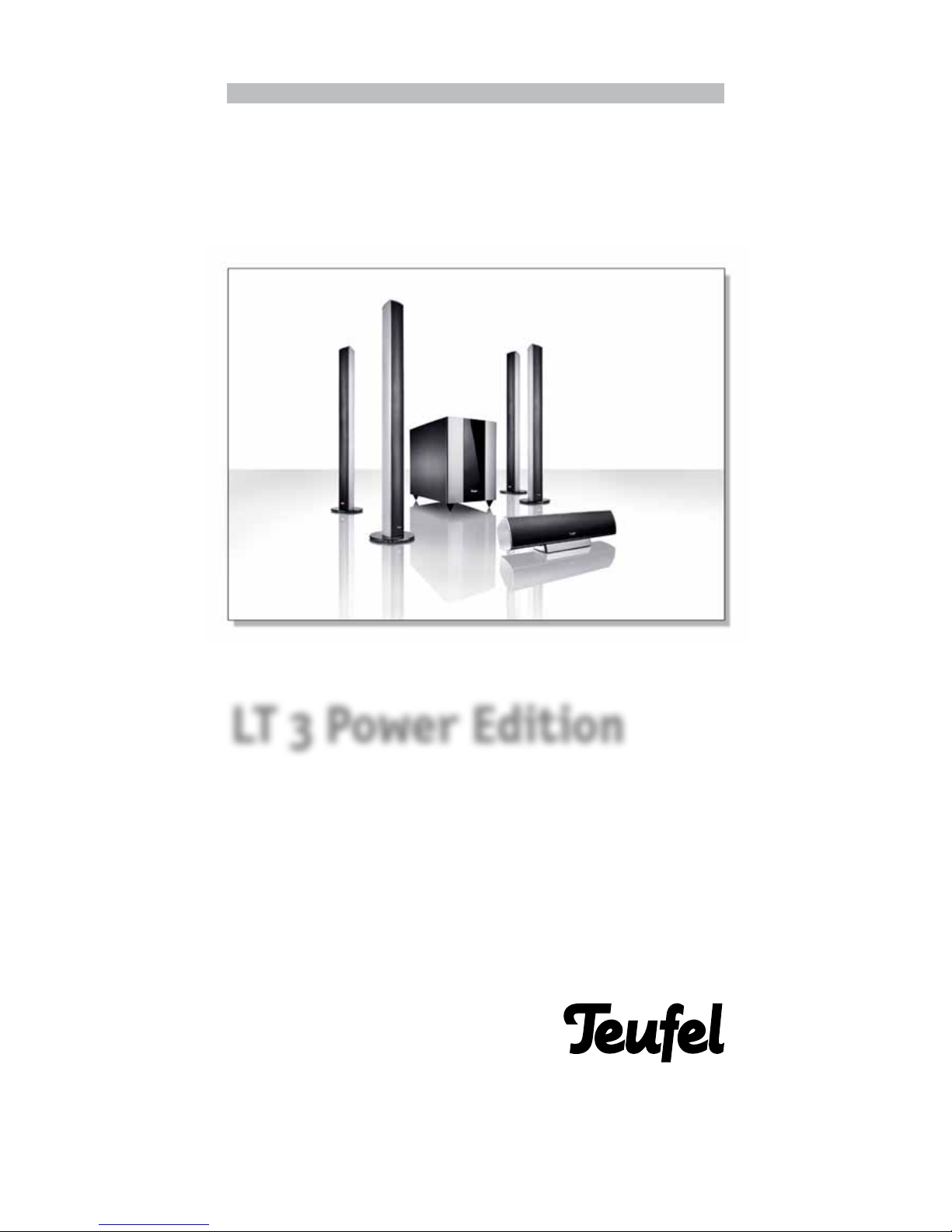
Technical Specifications and Operating Manual
5.1-Home Theatre Column Speaker System
with Active Subwoofer
LT 3 Power Edition
Page 2

2
· LT 3 PE
General note: Make sure to read this operating manual care-
fully and in its entirety. Before plugging in the units for the rst
time, make sure you have complied with all relevant safety and
operating instructions. Keep this operating manual in a safe
place so you can refer to it at a later date if necessary.
Always: If in doubt, consult the operating manual. Make sure
to comply with all instructions regarding the units' setup and
ongoing operation.
Cleaning: Only use dry or moist cloths to clean your speaker
cabinets Never use abrasive or alcohol-based cleaning products. If you need to clean a speaker membrane, do so very carefully using a dry cloth. Before cleaning a unit, always unplug the
power cable.
Humidity and sunlight: Never operate the unit in humid or
wet spaces, e.g., near a bath tub, shower, wash basin, drain, in
a damp basement, or near a swimming pool. Never expose the
loudspeakers to excessive humidity. Also avoid exposing them to
direct sunlight. Do not expose device to dripping or splashing
water. Do not place objects lled with liquids, such as vases on
the device.
Placement: Never mount the units loosely in a vehicle, on an unstable surface, on a loose stand, on unsuitable furniture, or with
insufcient bracing. The loudspeakers could topple and cause
personal injuries, which you will be liable for. Especially when
speaker cabinets are mounted on stands or placed on top of
TV sets/monitors, they may topple due to external stress (cable
being pulled, tr ipping over cable, accidental physical contact)
– even if they seem to be mounted quite securely. As a result
of their weight , toppling speaker cabinets can cause considerable damage, as well as becoming b adly damaged themselves.
The same applies to undersized or unprofessionally installed
wall-mounting brackets, particularly on light walls. Always use
adequately sized wall brackets for mounting loudspeakers, and
ensure that the wall can withstand the stress. Never mount the
units near a heat source. This could be a heater or oven, but
also any other electrical device that heats up during operation
(e.g., amplier). Similarly, never place a heat source on top of the
loudspeakers, such as a fan heater or candles.
Ventilation: There are several ventilation slits and openings in
the unit's housing. These are designed to ensure reliable operation and stop the unit from overheating. Never block or cover
the ventilation slits; do not place the unit on a soft surface
such as a bed, couch, carpet, etc., as this blocks the ventilation
slits in the bottom of the housing. Do not put any newspapers,
tablecloths, etc., on top of the unit. Most import antly, do not
cover up the heat sink of the amplier section or expose it to
direct sunlight. Conversely, you should generally not attempt
to provide additional cooling to the unit yourself. This is not
necessary.
Power source: Make sure to connect the subwoofer to a power
source that provides the correct voltage, i.e., the voltage indicated on the type plate. If you are unsure about the voltage
provided by your domestic power connection, please contact us
or your local electricity provider for advice. The unit does not
require earthing. When connecting to the mains power socket,
always use the supplied two-pole power cable. Under no circumstances should you modify the power cable, as it must comply
with the ofcial polarity and earthing regulations. Make sure to
plug the power cable only into a double-pole socket.
Make sure
the power switch is in the “off” position before connecting or
disconnecting the device.
Cables: Lay all the cables ush with the oor and walls. Avoid
any loops in your cables that could cause people to tr ip up.
Cable loops can also cause electrical interference and degrade
the sound quality. Make sure to lay your power cables out
of reach so that they are not stood on or squashed by heavy
objects. If you notice any cable damage, replace the cable. Pay
special attention to all plug connectors, the mains socket and
the subwoofer's connector panel. Regularly check all powered
cables to and from the loudspeakers for insulation issues and
breakage. If you detect a fault, immediately power down all connected units, unplug the cables and replace the defective cable.
Disuse: During prolonged periods of disuse (holidays, etc.), always unplug the subwoofer from the mains socket.
Thunderstorms: In the event of a thunderstorm, switch off and
unplug the unit as soon as you can in order to avoid damage
from lightning strikes.
Overloading: Never overload your wall sockets, extension
cables and multiboxes, or the integrated power sockets on
your electrical devices. Power overloads can cause short cir-
cuits and res. Also avoid turning up the volume control excessively on your amplier, particularly if you are also boosting
the bass frequencies (bass control, loudness button, bass boost
button, etc.).
Liquid and foreign substances: Liquids or other foreign sub-
stances should never get inside the unit, as they may interfere
with exposed live parts and cause short circuits or res. Absolutely avoid spilling any type of liquid onto the unit. In case of a
fault: Never attempt to repair the unit yourself. Always contact
our suppor t team rst and discuss the fault with them. If appropriate, they may give you instructions on how to clear the
fault. If this is not possible, send the unit directly to our service
address.
Transport: Take utmost care when transporting the unit , and
use a sack barrow if possible. Be aware that both the sack barrow and the unit can easily fall over as a result of sudden stopping or jolting (uneven ground, lurching movements, etc.).
Unusual noises: If any unusual noises occur during operation,
or if the sound gets distorted, immediately turn down the am-
plier volume to a level where the sound returns to normal.
Replacing the fuse:
Unplug the power cable before replacing the fuse. Make sure
that the replacement fuse has the same rating as the defective fuse.
Speaker volume: Excessive loudspeaker volume can cause irreversible hearing loss. The subwoofer may emit high sound
pressure levels very unexpectedly when it is suddenly triggered
into activity by a bass impulse (“Standby/Auto On” mode) – particularly if the unit is on full volume. As well as physical hearing
loss, also watch out for psychological stress caused by excessive
volume. Children and pets are particularly sensitive to noise. Always set the volume control of your audio system to a level that
is appropriate to the surroundings. When the system is playing
at high volume, do not stand too closely to the subwoofer and
never put your ears directly up to any of the loudspeakers.
Please read the following
safety guidelines
very carefully.
Packaging materials,
particularly plastic bags and
foils, should be kept out of
children's reach, as they can be
dangerous (e.g., risk
of suffocation)
Never leave your children
alone with electrical devices, as
there is always a risk of
electrical shock.
In case of an emergency:
Immediately disconnect the
unit's power plug from the
mains socket. In the following
cases, please contact one of our
service technicians:
4 Power plug or cable
is damaged
4 Liquid or
other foreign substances
have got inside the device
4 The unit has been directly
exposed to rain or another
type of liquid
4 The unit is inoperative
even though you have
followed all the operating
instructions
4
The unit has been dropped
or otherwise damaged
We are not liable for any incidents resulting from disregard
of the safety guidelines.
Safety guidelines
Page 3

3
· LT 3 PE
Contents
Safety guidelines
. . . . . . . . . . . . . . . . . . . . . . . . . . . . . . . . . . . . . . . . . . . . . . . . . . . . . . . . . . .Page 2
Table of contents. . . . . . . . . . . . . . . . . . . . . . . . . . . . . . . . . . . . . . . . . . . . . . . . . . . . . . . . . . . . . Page 3
Introduction . . . . . . . . . . . . . . . . . . . . . . . . . . . . . . . . . . . . . . . . . . . . . . . . . . . . . . . . . . . . . . . .Page 4
Unpacking · Included components . . . . . . . . . . . . . . . . . . . . . . . . . . . . . . . . . . . . . . . . . . . . . . Page 5
Accessories · Upgrading . . . . . . . . . . . . . . . . . . . . . . . . . . . . . . . . . . . . . . . . . . . . . . . . . . . . . . .Page 6
5.1 speaker placement . . . . . . . . . . . . . . . . . . . . . . . . . . . . . . . . . . . . . . . . . . . . . . . . . . . . . . . . Page 7
Connecting . . . . . . . . . . . . . . . . . . . . . . . . . . . . . . . . . . . . . . . . . . . . . . . . . . . . . . . . . . . . . . . . . .Page 9
Settings · Controls . . . . . . . . . . . . . . . . . . . . . . . . . . . . . . . . . . . . . . . . . . . . . . . . . . . . . . . . . . . Page 10
Subwoofer controls. . . . . . . . . . . . . . . . . . . . . . . . . . . . . . . . . . . . . . . . . . . . . . . . . . . . . . . . . . .Page 11
Problems and solutions · Cleaning . . . . . . . . . . . . . . . . . . . . . . . . . . . . . . . . . . . . . . . . . . . . . .Page 12
Manual version 1.1
About this document
The information in this document is subject to
change without warning. Lautsprecher Teufel
GmbH is in no way bound by the information provided herein.
Lautsprecher Teufel GmbH assumes no liability
for errors contained in this manual. No section
of this document may be reproduced or copied
by any electronic or mechanical means, including
photocopying and recording, without prior written consent from Lautsprecher Teufel GmbH.
© Lautsprecher Teufel GmbH
Version 1.1
July 2012 If you have any questions, suggestions or criti-
cisms, please contact our support team:
Lautsprecher Teufel GmbH
Gewerbehof Bülowbogen – Aufgang D1
Bülowstr. 66
D-10783 Berlin (Germany)
Ph.: 00800 200 300 40
Fax:+49(30) - 300 930 930
www.teufelaudio.com
Technical specifications
The various technical specications are given on
our website at www.teufelaudio.com
Customer complaints
If you have a complaint, we will require the following information:
1. Invoice number
As shown on your physical invoice (shipped with
the product) or on your order conrmation (PDF
format), e.g. 4322543
2. Serial number,
As shown on the rear of the unit,
e.g., Serial No.: LT 04007480121A
Thank you for your assistance.
Page 4

Technical Specifications and Operating Manual
4
· LT 3 PE
Introducing the LT 3 PE system
Dear Lautsprecher Teufel customer,
Thank you for purchasing speakers from
Lautsprecher Teufel.
You are now the owner of a powerful and sophisticated speaker system. All Teufel products are
meticulously manufactured and tted only with
top-quality components. Our LT 3 PE system is
designed for audio playback in room sizes of up
to 50 m2. Here, the room size only applies to the
part of the room being used for listening purposes. Adjacent parts of the room – such as a dining
niche – need not be factored into the room size. If
the room is higher than 3.5 m, multiply the room
size by 1.5.
Before using the speaker system for the rst
time, carefully read this operating manual. Keep
the manual in a safe place for later reference. If
you have any questions, feel free to contact our
technicians at 00800 200 300 40, or write us an
e-mail using the form provided on our website
(www.teufelaudio.com). Please provide your invoice number so that we can identify your purchase and provide the best possible support.
BEFORE you contact us with any questions,
make sure to read the “Problems and solutions”
section on page 12 of this operating manual.
Further answers are provided on the “FAQ/
Support” pages of our website: www.teufelaudio.
com.
Please read the safety instructions before using
the speaker system (supplementary document).
Page 5

Technical Specifications and Operating Manual
5
· LT 3 PE
Unpacking · Included components
Please check rst that the
system is complete.
Remember
Hold on to the cardboard boxes
for at least eight weeks (duration
of the right-of-return period).
Lautsprecher Teufel will ONLY
refund the full purchase price if
the speakers are shipped back in
their
ORIGINAL PACKAGING
!
Note:
The four passive column speakers
of the system are tted with
identical drivers with the same
technical data. Hence, these
column speakers can be used as
front or rear speakers.
Subwoofer L 4200 SW
Unpacking
Open the top aps of the cardboard box, remove
the packaging foam and carefully lift the speaker
out of the box.
We recommend that you keep the original packaging should you ever have to send the speakers
back to us for servicing.
The LT 3 PE speaker system is shipped as a com-
plete system in two conguration.
L 330 C Centre Channel
Speaker
Column Speaker L 330
FR including stand
Included components
LT 3 Power Edition Set 1
4 1 x L 4200 SW subwoofer
4 1 x L 330 C centre speaker
4 1 x stand for L 330 C
4 4 x spikes, hard
4 4 x spikes, soft
4 4 x L 330 FR column speakers
4 4 x stands for L 330 FR
4 1 x mains cable
LT 3 Power Edition Set 3
4 1 x L 4200 SW subwoofer
4 1 x L 330 C centre speaker
4 1 x stand for L 330 C
4 4 x spikes, hard
4 4 x spikes, soft
4 2 x L 330 FR column speakers
4 2 x stands for L 330 FR
4 2 x L 330 FCR satellite speakers
4 1 x mains cable
Table stand for L 330 C
Spikes, hard
Mains cable
L 330 FCR Satellite Speaker
Spikes, soft
Page 6
Technical Specifications and Operating Manual
6
· LT 3 PE
Accessories · Upgrading
If you require any optional
accessories, you can easily
order these directly from the
Accessories section of
our online store:
www.teufelaudio.com
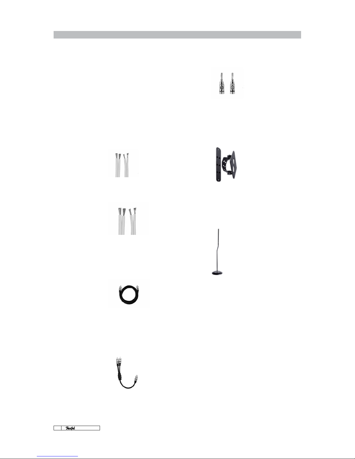
Teufel 2 x 2.5 mm2 speaker cable
The highly exible, unilaterally marked OFC cable
has sufcient diameter to
ensure unhindered bridg-
ing up to 15 meters. The
white casing is inconspicuous, and is offered as a
cable roll in two lengths: 15 or 30 meters.
Teufel Subwoofer Cable
Special RCA cable - devel-
oped for use with the sub-
woofer. The best connection
between an active sub-
woofer and an AV Receiver.
Protected via high-quality shielding against interference from other sources, with stable gold-plated
connectors to provide secure contact . The cable is
available in three different lengths, so your subwoofer can truly stand whereever you’d like it.
Y adapter
1 x socket to 2 x connector.
A Y adapter lets you feed
a mono sub signal to both
of the subwoofer’s stereo
inputs; this increases the
subwoofer’s overall volume.
Accessories
As different customers have different cable re-
quirements, our systems do not ship with any
standard speaker cables.
However, you can order suitable speaker cables,
subwoofer cables, adapters and connectors from
the Accessories section of our website at:
www.teufelaudio.com
Accessories for the LT3 Power Edition
The following accessories are available for the LT3
Power Edition:
Teufel banana plugs
These high-quality Teufel
all-round plugs enable you
to connect your cables to
your speakers in a cost-
efcient and reliable manner.
The stable screw grip rmly
holds all cables with a diameter up to 4 mm.
Permanently elastic spring contacts and genuine
gold-plating guarantee connections with very low
resistance.
Teufel Wall Mount Bracket AC 8500 SM
This all-purpose wall mount
is perfect for mounting
short column speakers. Many
of Teufel‘s centre and FCR
speakers can wall-mounted
using this robust cast-iron wall
bracket. In addition to vertical
installation, the AC 8500 SM also allows you to
mount a centre speaker horizontally. What‘s more,
you can then aim the speakers at the listening
position, since the wall mount offers three
different angle positions.
Teufel Stand AC 5001 SP
AC 5001 SP is the universal
speaker stand for »short«
columns or centre speakers
you cannot place on a shelf
or hang against the wall.
Its lofty height of 1085
mm automatically provides
for acoustically feasible
positioning of the speaker. A
metal base plate with a diameter of 245 mm gives
sturdy support to the 5 kg stand.
Available in black or silver.
Teufel 2 x 4 mm2 speaker cable
The OFC copper cable with
2 x 4 cross sections gives
an extremely stable connection and is, at the same
time, practically created.
Inconspicuous colours
(white casing) and high exibility through individual 0.08 qmm single wires guarantee an un-
complicated installation. This cable is offered as a
roll in two lengths: 15 or 30 meters.
Page 7

Technical Specifications and Operating Manual
7
· LT 3 PE
General notes on speaker placement
Thanks to its unobtrusive aesthetics and sleek
design, the Teufel LT 3 PE speaker system will easily blend into your living room. In order to achieve
the best possible audio quality from your Teufel
system, however, there are a few speaker placement rules to consider. These apply particularly
to home theatre applications.
As a general guideline, any home theatre system
should be concentrated around the viewing area,
i.e., that part of the room that contains the TV/
screen and the main seating areas. If at all possible, the TV/screen should be placed centrally in
relation to the viewing/listening spots.
Our speaker placement suggestions, shown over
the next pages, are designed for the best possible multi-channel sound reproduction in your
home. In the reality of your living room, of course,
there may be other factors working against the
suggested placements. While our recommendations represent the audiophile's optimum layout,
minor variations in placement will generally not
signicantly affect the sound imaging. Modern
AV receivers also offer many options to electronically compensate for compromises in speaker
placement. Always remember: Our recommendations are only to be considered a starting point.
Ultimately, you will know best what works in your
room, both visually and sonically. Trust your eyes
– and your ears!
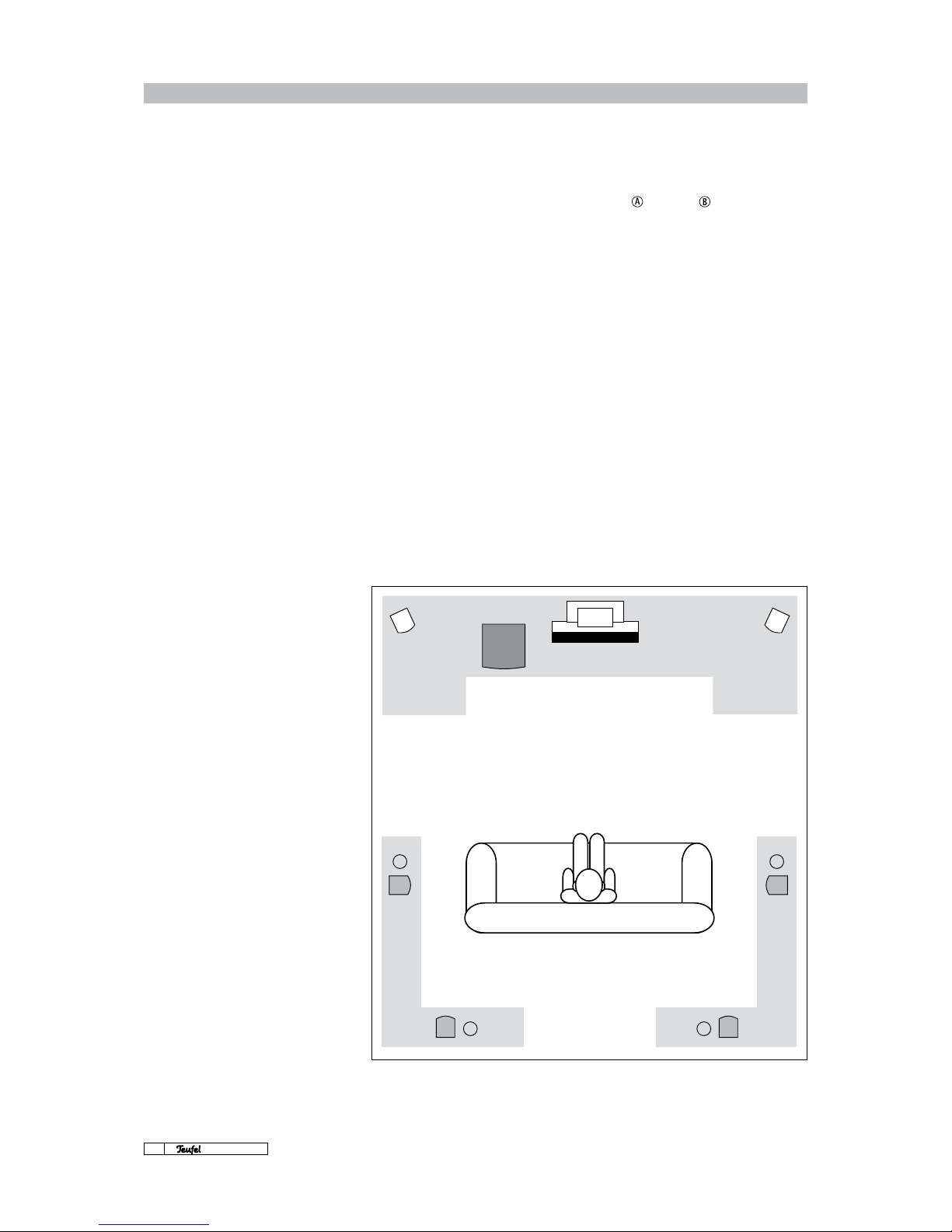
5.1 speaker placement
Centre
Since the centre speaker is responsible for all
spoken sound including lm dialogue, place the
centre speaker at a central location relative to
the main listening area to unite sound and image.
A good location is often directly above or below
your TV or screen.
You can also fasten the speaker directly to the
wall using the mounting brackets on the rear
(make sure to use suitable screws/wall plugs).
Front
The front speakers should be positioned similarly to conventional stereo speakers where they
form an equilateral triangle relative to the main
listening position. In a home theatre setup, the
TV/screen should be positioned in the centre between the left and right front speakers (tower
speakers L 330 FR). If you need to position the
column speakers further away, make sure to orient them towards the main listening spot.
Since they are magnetically shielded, you can
even place the two front speakers in close proximity to a conventional CRT TV.
Make sure that the centre speaker and the two
front speakers are positioned in a straight line, or
on a slight arc with the TV/screen. If the distance
between the listening position and the speakers
varies signicantly, the spatial imaging will suffer. Make sure to align your speakers properly to
exploit their full potential.
Hint:
The column speakers
sound best when
they are positioned
close to a wall.
SW Centre FrontFront
Page 8
Technical Specifications and Operating Manual
8
· LT 3 PE
5.1 speaker placement
We recommend
placing the subwoofer
in the grey front area.
The best default positions are
indicated by “A” and “B”.
We recommend
placing the rear speakers
somewhere in the
rear grey area.
Subwoofer
At the recommended crossover frequency of 100
or 120 Hz, the subwoofer can be positioned in the
room very exibly without affecting the output
from the other loudspeakers. The ideal position
is somewhere along the axis between the two
front speakers, but you should feel free to experiment with placing it anywhere you like. Since
the subwoofer is magnetically shielded, you can
even place it near a CRT TV. However, you should
never use it as a “TV table” since the bass vibrations may gradually move the TV until it slips off,
which could severely damage both units and possibly cause injury.
Rear
Position the left and right rear speakers either
to the side of or behind the main listening
spot.
The rear speakers should always be at least 1 m
away from the listener. If they are any closer to
the listening spot, make sure that the front of the
speakers is not directly pointed at the listener
but towards the centre of the room.
RearRear
A A
B B
RearRear
SW Centre FrontFront
Page 9

Technical Specifications and Operating Manual
9
· LT 3 PE
Connecting
You can connect the LT 3 PE system to any modern Dolby Digital/DTS 5.1/6.1/7.1 AV receiver. If you
own a 7.1 AV receiver, simply ignore the Rear Centre Out(s).
If your receiver is 5.1, connect the front, centre
and rear speakers as shown in Fig. 1.
Connect the subwoofer output (Sub Out) of your
Dolby Digital/DTS AV receiver to the right Line Input of the subwoofer using a mono RCA cable as
shown in Fig. 2.
In this setup, the left input (Line Input L) is not
connected. If you want to feed the Sub Out signal to both of the subwoofer's inputs for an additional bass boost, use a Y adapter (see Accessories, p. 6).
Connecting the loudspeakers
to an AV surround receiver.
Note:
The four passive column speakers
of the system are tted with
identical drivers with the same
technical data. Hence, these
column speakers can be used as
front or rear speakers.
Front, centre and rear speakers
Fig. 1
Subwoofer
Fig. 2
RCA line output
AV receiver
Sub Out
RCA line input
Input R
Subwoofer
AV receiver
Speaker output
Teufel
connection panel
L 330 FR
Front loudspeaker
left
L 330 FR
Front loudspeaker
right
L 330 FCR
Centre speaker
L 330 FR
Rear speaker
left
L 330 FR
Rear speaker
right
Subwoofer RCA line input
L 4200 SW
Active
Subwoofer
Page 10

Technical Specifications and Operating Manual
10
· LT 3 PE
Settings · Controls
Setting up the AV receiver
To take full advantage of your LT 3 PE Home Theatre System with Active Subwoofer, set the “Speaker Setup” section (Bass Management/Speaker
Management) of your AV receiver to “small” or
“normal” (not “large”) for the ve satellite speakers. This ensures that each speaker receives the
right amount of signal, and that the subwoofer
and front speakers have matching volumes. Also
in the receiver's “Speaker Setup” section (Bass
Management and/or Speaker Management), make
sure the subwoofer is set to “On”. Set the crosso-
ver frequency for the Columa 900 system to 100
Hz (or 120 Hz.)*
Setting up the subwoofer
If your system is based around an AV receiver, set
the subwoofer's Low Pass/Full Range switch to
“Full Range”; the AV receiver automatically determines the crossover frequency. Modern AV receivers determine the subwoofer's phase automatically. This happens within the receiver's “Speaker
Setup” utility, which analyses the distance between the different speakers and the listening
spot. For this to work correctly, the subwoofer's
own phase switch needs to be on “0°”.
If your system uses an older-model AV receiver
or another type of amplier without a setting for
the subwoofer distance:
The “Phase” control lets you adjust the subwoofer
to the satellite speaker so that the membranes
of all the speakers vibrate in the same direction
(“phase”) when reproducing signals around the
crossover frequency. If the phase is set incorrectly, this may cause a reduced bass response or
even bass cancellations.
If the subwoofer is positioned between the front
speakers, we recommend a phase setting of
“0°” (grey area in the diagram on page 8); if the
subwoofer is positioned closer to the listening
spot, a phase of “180°” may be more appropriate.
Similarly, the “180°” setting may help to eliminate
bass cancellations if you position the subwoofer
in other areas of the room. Always set the phase
control to the position where the bass response is
best. In order for the subwoofer's phase switch to
be active, the Low Pass/Full Range switch needs
to be set to “Low Pass”.
The subwoofer's output setting may vary slightly
depending on usage, e.g., home theatre sound
system or music playback. Whereas an actionpacked DVD typically contains very dened sub
bass signals, many music-only sources do not .
This is especially noticeable if your system is cali-
brated for optimum DVD playback. To nd the best
compromise between differing sound sources,
use your own subjective judgement.
Our recommendation is to determine the best
subwoofer volume gradually over time.
Avoid conguring the subwoofer volume automatically via your AV receiver's integrated room
analysis computer (advanced receivers only). Instead, set the subwoofer level provided in the
Bass Management/Speaker Management section
(“Speaker Setup”) to a high value, such as +8 to
+12 dB; this will guarantee that the subwoofer activates itself at the right times when in “Auto On/
Standby” mode. You can then use the subwoofer's
own level control to experiment with different
bass levels that are suited to your various listening scenarios
* Either of the
specied crossover
frequencies can be used.
Try both to nd out which
sounds best to you.
Page 11

Technical Specifications and Operating Manual
11
· LT 3 PE
Subwoofer controls
T
Low Pass – Full Range
With the switch on “LOW PASS”, the built-in controls
for “Phase” and “Frequency” are
activated.
With the switch on “FULL RANGE” (recommended
setting), these parameters are controlled by the
AV receiver.
Y
Level
Use the “LEVEL” control to adjust the subwoofer's
volume. In the receiver's bass management section,
set the bass level to a high value, i.e., between 8 and
12 dB. Next, set the subwoofer's level control to 10
o'clock. While the AV receiver is outputting its white
noise setup signal, slowly turn up the subwoofer
level to the desired volume.
U
Phase
This switch determines the phase relationship between the subwoofer and the front/centre speakers.
If the subwoofer is positioned in the speaker setup
as indicated on p. 8 (grey area of drawing), set the
phase to 0°. With other setups, the 180° setting may
produce better results.
I
Frequency
Use this control to set the crossover frequency between the subwoofer's bass signal and the bass fre-
quencies of the other speakers. If you are using an
AV receiver, set the receiver's crossover frequency
to 100 Hz or 120 Hz, and turn the subwoofer's fre-
quency control to maximum (hard right).
O
High Level In/Out
Use these speaker sockets to connect the subwoofer to a conventional stereo amplier without a dedicated subwoofer output. Do not connect anything
here if you are using a multi-channel AV receiver
with a Sub Out.
P
Power
“OFF” means that the subwoofer is switched off (LED
does not light up). “ON” means that the L 4200 SW
is operational (LED colour is red or green, depending on R)
{
Mains power socket
Plug in the power cable here.
}
Fuse
This is where the mains power fuse is located.
Q
Power LED
The power LED on the cabinet's front panel indicates the subwoofer's operating mode. Also see R.
W
Line Input
Connect the AV receiver's “Sub Out” to the subwoofer's “Line Input” using a mono RCA cable
(optionally with an additional Y adapter).
E
Line Output
Here, you can connect a second subwoofer for added
bass or to compensate for resonant frequencies in
the room.
R
Auto
The subwoofer provides two operating modes.
With the switch set to “ON”, the subwoofer is permanently on and playing back the audio signals
from its line input (LED is green).
With the switch set to “AUTO”, the subwoofer is in
automatic triggering mode. This means that the
subwoofer only activates once it detects a signal
at its line input (LED is green). After 20 minutes of
inactivity, the subwoofer automatically switches
itself off again (LED is red).
Q
What the icons mean
The lightning/arrow symbol
inside an equilateral triangle
informs the user
about the possibility
of a dangerous, non-isolated
electrical current
inside the device housing,
indicating the risk of
electrical shock.
The exclamation mark within
the equilateral triangle,
which can be seen on the
back of the unit, indicates
that there is important
operating and service
information for the
user to read.
This product complies with the
following European Union
guidelines:
2004/108/EC and 2006/95/EC.
The “wastebin” symbol printed
on the type plates and amplier
labels of our products signies
that Lautsprecher Teufel ensures
the proper disposal of its sold
loudspeakers and subwoofers
according to Germany's
Electrical and Electronic
Equipment Act.
All metal parts which could
cause a voltage error during
operation or maintenance must
be connected to a ground line.
Additionally, protection class I
devices must be connected to a
protective conductor.
Attention:
The separating equipment of
this equipment is the mains
plug, this separating equipment
must be usable without
difculties.
P
E
}
{
O
I
Y
U
T
R
W
Page 12

Technical Specifications and Operating Manual
12
· LT 3 PE
Problems and solutions · Cleaning
If you have any questions, suggestions or criticisms, please contact our support team:
No responsibility can be accepted for
the correctness of this information.
Subject to technical changes. Errors
and omissions excepted.
Lautsprecher Teufel GmbH
Gewerbehof Bülowbogen · Bülowstrasse 66
10783 Berlin · Germany
Ph.: 00800 200 300 40
Fax: +49(30) 300 930 930
www.teufelaudio.com
If neither of the operating modes is
available, (LED
Q
is
off) after you have
switched on the
P
power switch please
replace the fuse
}
.
Make sure that the
replacement fuse has
the same rating as defective fuse.
If the LED on the front panel lights up after you
switch on the
P
power switch, proceed as follows: Set the switch R to “On”, turn the subwoofer
volume level all the way down,
unplug the sub-
woofer's RCA cable from the amplier,
turn up
the volume slightly and touch the tip of the RCA
connector with your nger. If this produces a hum
or crackle, the fault is with the amplier or the
amplier
settings. If the subwoofer remains com-
pletely silent, please contact our support team.
The subwoofer is making a humming noise
Hum may be caused by any connected audio device as well as by problems with the mains power.
In most cases, excessive hum is caused by one of
the following:
1.
The subwoofer is connected to a different
electrical circuit
than the other components.
Make sure that all the connected devices are
powered from the same electrical circuit, i.e.,
the same mains socket.
2. The antenna connected to the audio sys-
tem or TV
has a different ground potential
than the antenna socket. To test this, simply
disconnect all the antenna cables from the wall
socket. If this makes the hum disappear, you will
need a ground breaker, which is available from
most electronics stores for 5 to 10 euros. Simply
insert the ground breaker between the antenna
socket and the TV/receiver.
3. A line lter (to be purchased separately)
can
also be useful for hum removal. Note that
you will need to connect all your electrical de-
vices to the line lter.
4. Some types of power multiboxes are also
known to produce hum. Try eliminating your
multibox and plug the subwoofer's power cable
directly into the mains socket.
5. Unplug the mains cable, rotate the connec-
tor plug by 180°,
and plug it back into the
mains socket.
6. If you have trouble locating the source of
the hum,
check whether the subwoofer is less
noisy when you plug it into the mains connection in another room. Also, try disconnecting the
subwoofer's RCA cable from the receiver to see
whether the hum is caused by one of the other
connected devices.
The subwoofer is not activating automatically
when in “Auto ON” mode
Some AV receivers default to a very quiet bass output on the Pre Out/Sub Out.
As a result, the subwoofer fails to activate, as the
weak signal does not cross its signal detection
threshold. In order for the subwoofer to correctly
activate/deactivate when in “Auto ON” mode, set
the subwoofer's own level control quite low (e.g.,
10 o'clock position) and increase the receiver's
subwoofer output level in the “Speaker Setup”
section – set it to the maximum value (+10 dB
or +12 dB), if necessary. This should resolve any
issues with the automatic signal detection. If it
does not, you can always run the subwoofer in the
regular “ON” mode, where it is permanently on.
The subwoofer is not working
Auto·On
R
220–240 V, Fuse T3.15AL/250V
220–240V~50 Hz 360 watts
On
Off
Power
P
{
}
Q
 Loading...