

Page 1
Technical specifications and operating instructions
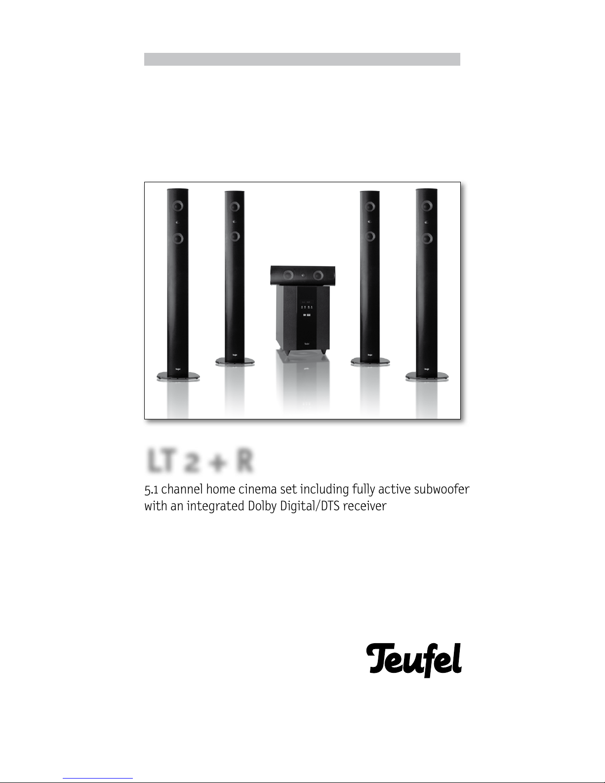
5.1 channel home cinema set including fully active subwoofer
with an integrated Dolby Digital/DTS receiver
LT 2 + R
Page 2
Technical specifications and operating instructions
2
· LT 2 + R
For your information
The information in this document may be changed without advance notification and does not
represent any obligation on the part of Lautsprecher Teufel GmbH.
Lautsprecher Teufel GmbH accepts no responsibility for any errors in this manual. No part of these
operating instructions may be copied in any way,
whether electronically, mechanically, using photocopies or recordings, or transferred without the
prior written agreement of Lautsprecher Teufel
GmbH.
© Lautsprecher Teufel GmbH
Version 1.3
March 2009
Warranty terms
12 year warranty for speakers and 2 year warranty for power amplifiers and electronics (from
purchase date) on materials and work time, with
the exception of damage caused by incorrect use
or electrical or mechanical overload. An original
copy of our invoice is required as the warranty
document. This warranty is exclusively valid for
speakers, power amplifiers and electronics that
have been purchased from Teufel for private use
by end customers. The warranty is not valid for
speakers, power amplifiers and electronics that
the end user has purchased from a different distributor. If the Teufel product is sold on privately,
the warranty may be transferred to the purchaser,
providing that the original proof of purchase is
also transferred.
Returns
Teufel guarantees an eight-week right of exchange or return with rebate of the purchase
price paid.
The return of individual components of a kit is
only permitted if these components can also be
purchased individually from Lautsprecher Teufel.
When one or individual components are returned, the price discount that Lautsprecher Teufel
guarantees for all components of a kit as part
of the set price shall no longer be valid. For the
components returned, customers shall therefore be refunded only the difference between the
set price and the purchase price of the individual
components that they are keeping. The economic
outcome for customers is as if they had bought
the remaining components at the individual price
from the outset.
You can find more information about returns on
the “returns form” that accompanies the delivery or on line in the support area of our web site
www.teufel.eu.
In the event of making a return, please do not
take any action without first contacting Lautsprecher Teufel.
We can only process and accept returns if you
have informed us first by phone and discussed
the procedure with us.
Please contact our service department if you
have any questions, suggestions or if there is
anything you think we could do better.
Lautsprecher Teufel GmbH
Gewerbehof Bülowbogen - Aufgang D1
Bülowstr. 66
D-10783 Berlin (Germany)
Tel.: +49(30) - 30 09 300
Fax:+49(30) - 30 09 30 30
www.teufel.eu
Complaints
If you have a complaint, it is essential that you
provide the following information so that we can
respond:
1. Invoice number
Found on the receipt (enclosed with the product)
or the order confirmation that you received as a
PDF file, e.g. 4322543.
2. Series or batch number
Found on the rear of the appliance,
e.g. batch no.: MO 04007480121A
Thank you for your support.
Technical data
You will find technical data on our website: www.
teufel.eu.
Trademark
® All trademarks are the property of their respective owners.
DOLBY
Manufactured under licence from Dolby Laboratories. “Dolby”, “Pro Logic” and the DD symbol are
trademarks of Dolby Laboratories.
DTS
Manufactured under license under U.S. Patent
#’s: 5,451,942; 5,956,674; 5,974,380; 5,978,762;
6,487,535 & other U.S. and worldwide patents
issued & pending. DTS and DTS Digital Surround
are registered trademarks and the DTS logos
and Symbol are trademarks of DTS, Inc.
©1996-2008 DTS, Inc. All Rights Reserved.
Page 3

3
· LT 2 + R
Contents
ML Version 1.3
Table of contents..............................................................Page 3
Safety information ............................................................Page 4
Introduction .................................................................Page 5
Unpacking · Contents ..........................................................Page 6
Accessories (optional)..........................................................Page 7
Setting up the 5.1 configuration.................................................Page 8
Function .....................................................................Page 10
Subwoofer front/display .....................................................Page 10
Subwoofer rear.............................................................Page 11
Remote control.............................................................Page 12
Operating elements: remote control .............................................Page 13
Connection ..................................................................Page 14
Signal sources with digital outputs ............................................Page 14
Signal sources with analogue outputs ..........................................Page 15
Aerial · Speakers ............................................................Page 16
Start-up .....................................................................Page 17
Setting up the surround system.................................................Page 18
Playback .....................................................................Page 20
Digital signal sources and analogue signal sources • Listen mode • Night mode .........Page 20
Radio programmes ..........................................................Page 21
Frequently asked questions.....................................................Page 22
Frequently asked questions · Cleaning............................................Page 23
Glossary .....................................................................Page 24
Page 4

Technical specifications and operating instructions
4
· LT 2 + R
Safety information
Important: Please read through these operating instructions
very carefully. It is essential that you take note of all of the safety information and operating instructions before switching on
the appliance. Please keep these operating instructions in a safe
place for future reference.
Important: Please read the operating instructions. You should
also follow all instructions for start-up and ongoing use.
Information on cleaning: Please do not attempt to clean the
appliance using household chemicals because they could damage
its surface. Simply use a dry cloth. Disconnect the appliance from
the mains before cleaning.
Caution – moisture and sunlight: Never operate the appliance
in damp rooms, i.e. close to baths, showers, wash basins, drains,
damp cel lars or swimming pools; never us e it where there
is moisture. Never expose the speakers to high air humidity
and avoid direct sunlight. Do not expose device to dr ipping or
splashing water. Do not place objects filled with liquids, such as
vases on the device.
Information on location: Do not use the appliance unsecured
in vehicles, in unstable places, on wobbly tripods or furniture or
supports that are too small. The speakers could fall and cause damage to people, including yourself. Speakers, particularly if positioned on stands or on the TV/monitor, may fall and cause damage
due to their weight, even if they have been positioned securely
and stably, as a result of external influences (pulling on the cable,
tripping over the cable, unintentional physical contact). This also
applies to wall suppor ts that have been attached inappropriately or incorrectly to walls that may not be capable of suppor ting
their weight. Only use suitable wall brackets for mounting. Make
sure that you know how much weight the walls can bear. The appliance must not be placed near sources of heat. This includes
radiators and heaters, ovens and other appliances that emit heat
(e.g. amplifiers). Sources of heat , such as fan heaters or candles,
should not be placed on the speakers.
For ventilation: Any slits and openings in the casing have been
provided for ventilation. Their purpose is to guarantee reliable
operation and to prevent the appliance from overheating. These
openings must not be blocked or covered, including by placing
the appliance on a bed, sofa, carpet or other soft surface. Do not
place any newsp apers or table cloths, etc. on the appliance. The
cooling plate of the amplifier electronics must not be covered or
exposed to direct sunlight. Additional active cooling of the appliance is generally not permitted.
Electrical supply: The subwoofer must only be supplied from a
power source with the correct voltage as specified on the identification label. If you are unsure about the electricity supply
in your home, please contact us or your electricity supplier for
more information. The device must be grounded. Please only use
the appropriate power cable for connecting to the power socket.
Do not modify the power cable under any circumstances! You
must comply with regulations regarding polarity and grounding.
The power socket of the device will only accept a 3-pin power
plug. Make sure the power switch is in the “off” position before
connecting or disconnecting the device.
Information on wiring: Please place the supply cable flat and
flush to the wall and floor. Cables that are laid loosely represent a
risk of tripping. This could also result in interference and cause
the sound to be disrupted. The electricity supply cable should
be laid so that it is not likely to be stepped on or squashed from
the sides or above by heavy objects. Damaged cables must be
replaced. Pay particular attention to the cable/plug connection,
the mains socket and the cable output from the subwoofer. The
power supply cable and the cables that connect the speakers
should be checked regularly for insulation faults or breaks. If a
fault is discovered, the appliance and the cabling must be disconnected from the mains immediately and the defective cable
must be replaced.
During periods without use: Remove the subwoofer ’s power
supply cable from the socket for longer periods of absence or
non-use.
During thunderstorms: In order to avoid damage caused by
lightning str ikes, the appliance should be switched off and also
detached from the mains socket as soon as a thunderstorm is
expected.
Risk of overload: You should not overload wall sockets, extension cables or integrated appliance sockets, because this could
potentially lead to short circuits and even fires. You should also
avoid turning up the volume very high on the relevant amplifier,
especially if you have increased the bass using the bass control,
the loudness button or one of the deep bass boost switches.
Foreign bodies and liquids: Foreign bodies and liquids must not
get into the appliance via its openings under any circumstances,
as they could come into contact with par ts carr ying high voltages, which could then cause shor t circuits and fires. Therefore
do not spill any liquids of any kind on the appliance. Troubleshooting: Do not attempt to repair the appliance yourself. Contact our
service depar tment first for authorisation if you think that you
can repair the fault yourself. Otherwise the appliance must be
sent to our service depar tment.
Transport: The appliance should be transported using a hand
truck. Great care must be taken during transport . Please note
that uneven surfaces, sudden stopping or inappropriate exertion
of force may cause the hand truck and the load to fall over.
Information on spare parts: Lautsprecher Teufel will provide
you with spare parts during the warranty per iod. Your warranty
will not be invalidated if you replace the parts yourself on-site
using Lautsprecher Teufel spare parts.
Unusual sounds: If any unusual sounds occur during use or the
sound becomes distorted, the speaker output must be reduced
immediately so that the system plays an undistorted sound.
Connecting and changing the fuse:
Disconnect the mains plug. A faulty fuse may only be exchanged
for one of the same type.
Information on volume: Loud noises can damage hearing. Sudden high pressure may be created, par ticularly if a “subwoofer”
in “Standby/Auto On” mode is switched on by a bass impulse at
full volume. In addition to physical damage, please be aware of
possible psychological consequences. Children and pets require
particular care. If necessary, set the volume control of your signal source appliance to the lowest level. At high volumes, always
keep a cert ain distance from the appliance and never have your
ears right next to the speaker.
Please read the following
safety information carefully.
Risk of suffocation – keep
packaging materials (e.g. the
plastic lm) out of the reach and
sight of children.
Risk of electrocution – do not
leave children unsupervised with
electrical appliances!
In case of emergency
If any of the following occur
disconnect the appliance from
the mains and consult our technicians:
4 If the plug or cable are
damaged
4 If foreign bodies or liquid
have entered the appliance
4 If the appliance has been in
direct contact with rain or
other water
4 If the appliance does not
play, even though you have
followed the operating
instructions
4
If the appliance has been
dropped or damaged in some
other way
We cannot accept any responsibility for incidences that occur
because safety information has
not been adhered to.
Page 5
Technical specifications and operating instructions
5
· LT 2 + R
Introduction LT 2 + R
Dear Lautsprecher Teufel customer,
Thank you for buying the home cinema system
LT 2 + R from Lautsprecher Teufel.
You have purchased a very high-performance 5.1
channel home cinema system: Lautsprecher Teufel
speaker systems are equipped with high-quality
components and are assembled with extreme care.
The associated L2200/6 SWR, a fully active subwoofer with six integrated end stages, can deliver
output in addition not only to its own subwoofer
but also to five satellite speakers for treble and
mid-range sounds and thus forms the basis of the
5.1 home cinema set. You can found connection
details on pages 14 and 15 of these instructions.
We recommend the LT 2 + R for providing sound in
rooms up to 35 m
2
in size.
Before operation please read these instructions
carefully and store them in a safe place for future reference. If you have any further questions,
please contact our engineers on tel. +49 (30)
-300 9 300 or use the e-mail contact form on our
website www.teufel.eu. Please have your invoice
number ready, so we can immediately locate your
product and provide the best possible support.
BEFORE contacting us with a question, please read
the “Problems and solutions” section on pages 22
to 23 of these operating instructions and visit
our website (www.teufel.eu) where you will find answers to many questions in “FAQ/Support”.
Please refer to our safety information on page 4
of these operating instructions and only use the
speaker once you have read the safety information.
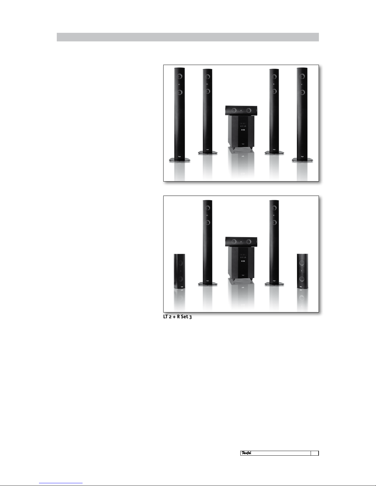
LT 2 + R Set 1
LT 2 + R Set 3
Page 6
6
· LT 2 + R
Unpacking
Fold back the flaps on the upper side of the box,
remove the polystyrene pieces and carefully lift
each speaker out of the box. Alternatively you can
fold back the flaps on the top of the box and turn
the box with its contents on its head. Then lift the
box from the contents and remove the internal
packaging. For your own benefit we recommend
that you do not dispose of the box, in order to guarantee safe transport if the appliance requires
servicing later on.
Unpacking · Contents
First please check that the
delivery is complete.
Please note:
Please keep the boxes for at least
the eight-week return period,
as we can ONLY repay the full
purchase price if the products
are returned in the ORIGINAL
PACKAGING in which they were
supplied!
VHF/FM auxiliary aerial
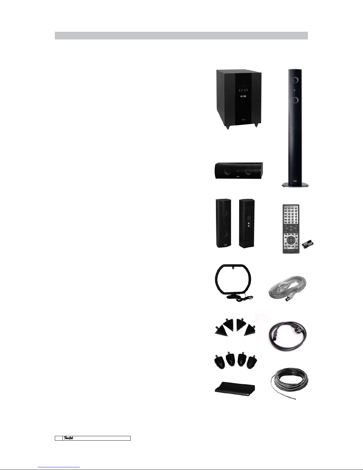
Contents
LT 2 + R - Set 1
4 1 x LT 2 + R subwoofer L2200/6 SWR
4 1 x centre speaker L220C
4 4 x column speakers L220FR
4 1 x subwoofer remote control
4 2 x batteries for remote control
4 1 x base for L220C
4 4 x spikes, hard
4 4 x spikes, soft
4 1 x VHF/FM auxiliary aerial
4 1 x MW/AM frame aerial
4 1 x speaker cable (30m)
4 1 x mains cable
LT 2 + R - Set 3
4 1 x LT 2 + R subwoofer L2200/6 SWR
4 1 x centre speaker L220C
4 2 x rear speakers L220FCR
4 2 x column speakers L220FR
4 1 x subwoofer remote control
4 2 x batteries for remote control
4 1 x Fbase for L220C
4 4 x spikes, hard
4 4 x spikes, soft
4 1 x VHF/FM auxiliary aerial
4 1 x MW/AM frame aerial
4 1 x speaker cable (30m)
4 1 x mains cable
MW/AM frame aerial
LT 2 + R subwoofer
L2200/6 SWR
Rear speaker L220FCR
Remote control
2 x batteries
Centre speaker L220C
Column speaker L220FR
Spikes, soft
Base for L220C
Spikes, hard
Accessories
Other connection cables or subwoofer casters
are not included as a result of the different
requirements. You can, however, order any required accessories directly from us. You will
find the optional accessories for the LT 2 + R
Dolby Digital/DTS subwoofer on the following
page.
Mains power cable
Warning:
Inappropriate replacement of
the battery may cause explosion.
Replace only with batteries of
same type. Do not expose the
battery to excessive heat such as
sunshine or re.
If you plan to not use the device
for a longer period of time:
remove the batteries from
remote control and store them
appropriately to prevent possible
damage from leaking.
speaker cable
Page 7
7
· LT 2 + R
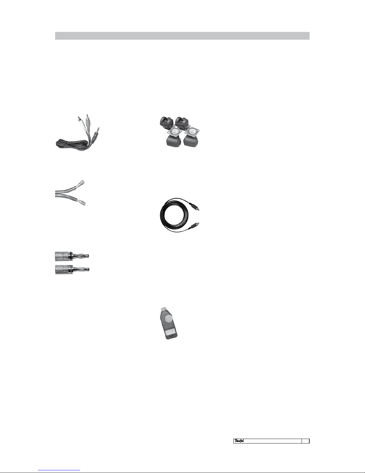
Teufel volume level measuring device
Do not rely on your ears. Equalising
your home cinema system works
much more precisely with the aid
of a volume measuring device. A
purchase that will last a lifetime!
All optional accessories can
easily be ordered as required,
e.g. from the accessories area
on our website:
www.teufel.eu
Optional accessories for the LT 2 + R
Here is an overview of the relevant accessories
available for your Teufel home cinema set.
Teufel Y adapter cable
If you want to connect
an appliance (e.g. MP3
player) that only has a
mini-jack output – and
the mini-jack input “PC”
is already occupied –
this cable is suitable for
connecting the appliance with the “VCR” or Aux”
cinch inputs. Available in three lengths.
Teufel casters
These black casters, characterised by a particularly flat construction height,
make your Teufel subwoofer
mobile in no time at all. This
makes the back-breaking
carrying round of the subwoofer when testing the ideal subwoofer position
a thing of the past. They are also very practical
when cleaning. These casters can be used instead
of the supplied resonance damper.Teufel speaker cable, 2 x 2.5 mm
2
This highly flexible copper wire
with transparent sheath and
marking to indicate polarity is
suitable for the satellite spea-
kers on your Concept S-system.
The 2 x 2.5 mm2 cable can be used for a length
of 15 metres. Due to a high number of customer
requests, our cable is precut to practical lengths
of 10 to 50 metres.
Oehlbach Red Opto optical fibre
These thin plastic lines are used to transfer digi-
tal data between the CD, MD
and amplifier/receiver and
between the laser disc and
DVD player and the AV appliance. The cables are now
supplied with an adapter for
CD and MD Walkmans. The
black optical cable has a 5.5 mm diameter and is
the first choice for high quality home cinema and
THX systems.
A 0.5 m optical connection cable is already included as standard. If you have to cover longer distances or simply want better quality, please use
our online shop to order the Oehlbach Red Opto
optical fibre cable. The Red Opto cable is available
in lengths of 0.5 to 6 metres.
Accessories (optional)
Teufel banana plug
These high-quality Teufel
all-round plugs enable you
to connect your speakers to
an amplifier or receiver in a
cost-effective and reliable
way. A stable screw grip
firmly holds all cables with a diameter up to 4 mm.
Permanently elastic spring contacts and genuine
gold-plating guarantees plug connections with
very low resistance. Supplied in pairs, one red
plug and the other black.
Page 8

8
· LT 2 + R
General information on configuration
Much more important than for a stereo system,
home cinema systems must observe certain set
up criteria in order to optimise the sound quality when using a multichannel surround sound
system.
For home cinema systems, we recommend concentrating on the area actually used – i.e. the
(part of the) room where the TV/screen and seats
are located. The TV/screen should be positioned
as centrally as possible to the listening location.
The recommended set-up (on the following pages)
represents the best possible arrangement for
perfect multichannel playback at home. Your
available space, your partner or furniture may
not always permit such ideal placement. Try to
meet as many requirements as possible. Small
variations are not a problem. The L2200/6 SWR offers options for compensating electronically for
any compromises in the set up. Generally speaking, the following rule always applies: you can
always use our recommendations to experiment
with what works best acoustically and optically.
Let your ears (and eyes) decide!
Setting up the 5.1 configuration
Subwoofer
The location of the subwoofer is freely selectable
and does not affect the other speakers. Placement within a straight line between the two front
satellites is ideal. But you can also try it out at any
other location in the room. Thanks to its magnetic screening, the woofer can also be placed near
the TV. We must, however, advise you not to use it
as a “TV table” as the subwoofer’s vibration may
cause the TV to “wander” – with potentially damaging consequences to the appliance and users.
For ideal communication between the subwoofer
and remote control, it is essential for the front of
the subwoofer to be aimed towards the listener.
Centre
As the centre plays back all voice information, including the actors’ dialogues, the centre speaker
must be as central as possible to the listening position or located above the TV/screen so that the
sound and image make up a harmonious unit.
SW Centre FrontFront
We recommend placing
the subwoofer in
the front grey area.
Page 9

9
· LT 2 + R
Setting up the 5.1 configuration
We recommend placing
the subwoofer in
the front grey area.
We recommend placing
the rear speakers in
the rear grey area.
Select position area A or B.
Rear
The rear speakers should be set up to the left and
right either to the side or behind the listening
location – ideally at the same height as the front
speakers, e.g. on a shelf or directly on the wall.
The speakers can be fixed higher than the front
speakers (up to 2.10 m); but we advise you not to
locate them lower.
We always recommend that the distance between
the rear speakers and the listening location is
more than 1.00 m. But if you (have to) sit closer,
please ensure that the front of the speaker is
not pointing directly at you but rather angle the
speakers more into the room. Or create a greater
distance by positioning the speakers higher than
1.20m.
Rear
A
B
Rear
SW Centre FrontFront
Rear
A
B
Rear
Front
Using the old stereo tradition (distance to listener = distance between the left and right
speaker), the front speakers are set up next to
the TV/screen with the same distance to left and
right or fixed to the wall. If the speakers have to
be placed further out, you can easily turn them
inwards and towards the listening location.
The following applies if the front speakers are
fixed to the wall or placed on shelves: select a
set-up height of between 40 centimetres and
1.20 metres (lower edge). It is important that the
centre and front speakers are approximately in
a line, or possibly even on a slight arc to the TV.
Otherwise the homogeneity of the playback may
vary with run time differences. Setting the speakers up in this way allows them to deliver their full
sound potential.
Page 10

10
· LT 2 + R
Button names and their functions
Standby
Switches the subwoofer on (press once) or off
(press again) after the power supply has been initiated on the rear (“Power” – see page 11) of the
appliance. A blue LED indicates that the device is
on standby.
Input
Select the input signal with this button. The
next input is activated every time the button is
pressed.
Volume +
This increases the overall volume of the system.
Volume –
This decreases the overall volume of the system.
The display always shows the selected signal source during operation, e.g. “Coax” and the playback
mode, e.g. “AC3” = Dolby Digital. This display is interrupted if you make a change, e.g. to the volume. As soon as this activity is ended, the display
indicates the originally selected signal source
again.
Function: Subwoofer front/display
Page 11

11
· LT 2 + R
Connection names and their functions
Q
FM
Connection for FM/VHF auxiliary aerial
W
AM
Connection for AM/MW aerial
E
Digital input
Optical: For connecting the L2200/6SWR with a
digital signal source in optical format (Toslink).
Coaxial: For connecting the L2200/6SWR with a
digital signal source in coaxial format.
R
Analogue input
PC: This is used to connect the sound card output
(“Audio Out”) on your desktop PC or notebook to
the L2200/6SWR using an optional stereo minijack cable. Alternatively, you can connect an MP3
player.
Aux/VCR: You can connect the cinch cables (left/
right) with the analogue outputs of your stereo
reproduction appliances (e.g. TV set, CD player, video recorder, etc.). The input called VCR (= video
recorder) can also be used with other signalling
appliances such as a MiniDisk player, cassette recorder etc. You will need an additional equalizer/
preamplifier to connect and operate an analogue
record player.
T
Speaker output
Here you connect the two-core speaker cables [+]
and [-] from the five satellite speakers.
Y
Power mains power switch
When set to “Off”, the subwoofer is switched off,
and on when it is set to “On”.
Explanation of symbols
The arrow-headed lightning
symbol in an equilateral triangle
indicates the presence of a
dangerous uninsulated electrical
voltage within the system
housing and therefore a risk of
electrical shock.
The exclamation mark in an
equilateral triangle, as afxed
to the appliance, is to make
the user aware of important
operating and maintenance
instructions..
This product complies with
European Community guidelines
2004/108/EC and 2006/95/EC.
The dustbin symbol printed
on our products’ type plates
and ampliers states that
Lautsprecher Teufel guarantees
proper disposal of these speakers
and subwoofers in line with the
Electrical and Electronic Appliance Act.
Attention:
The separating equipment of
this equipment is the mains
plug, this separating equipment
must be usable without
difculties.
Function: Subwoofer rear
W
T
Y
Q
E
R
Page 12

12
· LT 2 + R
Button names and their functions
ĕ Explanation of functions on the following page
Function: Remote control
POWER
CHANNEL
CENTER WOOFER
REAR-L REAR-R
SCAN
MUTE OPT COAX
VCR AUX
1
4
7
2
5
8
3
6
9
10+
MEM
PC
STEREO/MONO
NIGHT MODE
LISTEN MODE
TEST
C DELAY
RESET
TUNER
S DELAY
B
A
S
S
T
R
E
B
L
E
+
–
+
–
–
+
–
+
– + – +
+
––
+
Balance
L R
V
O
L
U
M
E
+
V
O
L
U
M
E
–
O
Channel
I
Scan
W
Mute
U
Mem
Y
Stereo/mono
switch
T
Station buttons
switch
P
C Delay
{
Te st
q
Listen Mode
w
Reset
e
S.Delay
Q
Power
}
Night Mode
r
Centre/
Woofer
t
Bass
p
Rear
»L« »R«
u
Volume +
y
Treble
i
Volume –
o
Balance
»L« »R«
E
Input selection
R
Station buttons
Page 13

13
· LT 2 + R
Q
Power
Switches the subwoofer on (press once) or off
(press again) after the power supply has been
initiated on the rear (“Power” – see page 11) of
the appliance.
W
Mute
Pressing the button once immediately mutes
the complete system; if you press it again, the
system returns to its previous operating status.
If the system has been switched to mute, the
“MUTE ON” message on the display lights up; on
reactivation “MUTE OFF” lights up briefly before
the input source appears again, e.g. “OPT”.
E
Choice of input
Here you select the five inputs plus the integra-
ted radio receiver. ĕ Page 20
R
Station buttons
Nine buttons allow the radio stations saved by
the user to be selected directly. ĕ page 21
T
Station buttons switch
Enables the programming of other radio presets.
Press once for positions 11–19, twice for 20–29,
3 x 30. ĕ page 21
Y
Stereo/mono switch
When receiving weaker VHF/FM stations via room
aerials, the playback quality may improve noticeably if you switch to mono.
U
Mem
Memory button to assign the station buttons (4).
ĕ page 21
I
Scan
For radio operation you can run through the
frequency bands manually to get to the next
station – in ascending [+] or descending [-] order.
ĕ page 21
O
Channel
In “Tuner” mode you can switch directly from station
to station – in ascending [+] or descending [-] order.
ĕ page 21
P
C.Delay
Option to set the delay on the centre speaker.
Only works with Dolby Digital/DTS.ĕ page 19
{
Test
Initialises the test sound to equalise the speakers.
ĕ page 18
}
Night Mode
For Dolby Digital signals, this activates volumereduced playback with acoustic adaptation to
a lower volume level. Press again to deactivate
Night Mode. ĕ page 20
q
Listen Mode
Used to select the various playback modes such
as Dolby Prologic II or stereo. If a Dolby Digital
signal is active, stereo mode is forced by pressing
this button. ĕ page 20
w
Reset
Call up the subwoofer ’s factory settings using
this button.
e
S.Delay
Allows the delay of the rear loudspeaker to be
set. Only works with Dolby Digital/DTS and Dolby
ProLogic II. ĕ page 19
r
Centre/Woofer
Press [+] and [-] to set the
desired level for the centre and subwoofer.
t
Bass
Press [+] and [-] to set the
desired level for the centre and subwoofer.
y
Treble
Use the [+] and [-] keys to set the required bass
level. It works directly on both front speakers.
u
Volume +
This increases the overall volume.
i
Volume -
This reduces the overall volume.
o
Balance »L« »R«
The “L” and “R” buttons increase the respective
amounts of sound output from the left (“L”) or
right (“R”) front speakers. Pressing the “Balance”
button will return the sound output to the original balanced state.
p
Rear
Use the [+] and [-] keys to regulate the required
levels of the left and right rear speakers.
Tip:
The settings you make are
saved directly by the subwoofer
without any need for further action. They remain available even
after the mains power has been
switched off and on again.
Operating elements: Remote control
Page 14

14
· LT 2 + R
Connection: Signal sources with digital outputs
* Only users of the Xbox
Advanced AV Pack and High
Denition AV Pack have
a digital output
Connection to appliances with digital outputs
for surround or stereo playback
Multichannel sound card, DVD-player/recorder,
sat receiver, PlayStation®2 & 3, Xbox 360®*...
Multichannel sound card,
DVD player/recorder,
sat receiver,
PlayStation®2 & 3,
Xbox 360®*...
L2200/6SWR
DIGITAL INPUT
OPTICAL
COAXIAL
Digital connection cable (coaxial)
Digital connection cable (optical)OPTICAL OUT
COAXIAL OUT
The L2200/6SWR is perfectly suited for combination with a maximum of two of the appliances listed
above.
Connect the playback appliances as shown in the
illustrations.
You connect these appliances via their Digital Out
outputs using an appropriate cable to inputs of the
same type (coaxial or optical) on the subwoofer.
The internal Dolby Digital/DTS decoder on the subwoofer automatically recognises the signal transferred via the digital input , decodes the data flow and
converts it into an audible 5.1 sound experience.
You will find further information on operation on
page 20.
Page 15

TV
Videorecorder
PC
15
· LT 2 + R
L
R
L
R
L
R
L
R
Connection: Signal sources with analogue outputs
L2200/6SWRANALOGUE SIGNAL SOURCE
Connection to appliances with analogue outputs for stereo playback
2-channel sound card, MP3 player, TV set,
CD player and video recorder …
In addition to the two digital inputs the
L2200/6SWR has a total of three analogue inputs:
[VCR] [Aux] [PC]. These can be used with the analogue appliances of your choice. This requires
either a stereo cinch cable [Aux] [VCR] or 3.5 mm
stereo mini-jack cable [PC] for each device. *
Connect the playback devices as shown in the
illustrations.
* These cables are usually
enclosed with the stated
appliances.
When connecting the
appliances, please note the
relevant information in the
handbooks for the components used.
ANALOG INPUT
PC
VCR
AUX
ANALOG INPUT
PC
VCR
AUX
L R
L
R
AUDIO OUT
L
R
AUDIO OUT
L R
ANALOG INPUT
PC
VCR
AUX
L R
LINE OUT
Page 16

Technical specifications and operating instructions
16
· LT 2 + R
Connection: Aerial · Speakers
* To be purchased
separately
Please ensure that no
individual exposed wire from
a cable comes into contact
with any free terminals, the
rear of the appliance or other
uninsulated cables (e.g. from
other speakers).
Please note:
Connecting the cables with
the incorrect phases can result
in thin sound, weak bass and
reduced stereo characteristics.
For multichannel surround
systems, too, it is important that
all speakers are connected with
the correct polarity in order to
ensure an appropriate three-
dimensional atmosphere and the
correct alignment of the sound.
Connecting the aerial
The use of the supplied aerials is essential as a
minimum requirement for disturbance-free reception. Please connect the aerials as shown in
the illustration.
A standard coaxial plug at the end of a coaxial
cable* (e.g. a cable connection) can be connected
directly with the FM coax input (in place of the
supplied auxiliary aerial).
Connecting the satellite speakers
The five satellite speakers for the treble and mid
ranges are connected via speaker cables to the relevant speaker outputs front L/R, rear L/R and front
centre on the subwoofer. To do this, strip the ends of
the speaker cable (about 7 mm) and twist the cable.
The speakers and the fully active subwoofer have
corresponding [+] and [-] terminals. It is important
that you observe the correct polarity when connecting the speakers: the plus pole of the speaker
to the plus pole of the subwoofer amplifier and the
minus pole of the speaker to the minus pole of the
subwoofer amplifier (“Speaker Output”). To do this,
press the clip and insert the ends of the cable.
FM
ANTENNA
GND
AM
VHF aerial MW frame aerial
(supplied)
75 Ohm
COAX cable
VHF
Auxiliary aerial
(supplied)
R
+
–
REAR SPEAKER
RIGHT
+ –
FRONT SPEAKER
RIGHT
+ –
REAR SPEAKER
LEFT
+ –
FRONT SPEAKER
LEFT
+ –
CENTRE
+ –
FL C RL FR RR
SPEAKER OUTPUT
+
–
Cable connection
Page 17

Technical specifications and operating instructions
17
· LT 2 + R
Start-up
First ensure that all cables are connected as described above and insert the mains cable into the
socket.
Switch the main power switch [Power] on the back
to “On” to activate the 5.1 amplifier on the subwoofer. The blue LED lamp lights up on the left of
the operation panel on the front of the subwoofer.
The “Input”, “Volume+” and “Volume-” buttons on
the operating panel have no (activated) function
(yet). The subwoofer starts operation when you
press “Standby”.
By pressing “Input” repeatedly you can activate
all inputs in succession: “Opt”, “Coax”, “VCR”, “Aux”,
“PC”, “Tuner”.
You can set the desired overall volume using the
“Volume [+] and [–]” buttons.
With the L2200/6SWR, it is possible to make all
settings using the remote control. To do this,
please first insert the batteries into the remote
control’s battery compartment as per the illustration:
If the appliance no longer reacts to the remote
control, even when it is used in direct proximity
to the subwoofer, please change the batteries.
Please note:
1) Do not combine new and old batteries
2) Do not use different types of batteries
3) Observe the polarity – see battery
compartment
For proper operation it is necessary to direct the
remote control towards the subwoofer from a distance not exceeding 5 metres and at a horizontal angle of no more than 30 degrees.
ĕThe remote control’s functions are explained
on pages 12/13.
Page 18

Technical specifications and operating instructions
18
· LT 2 + R
Setting up the surround system
POWER
CHANNEL
CENTER WOOFER
REAR-L REAR-R
SCAN
MUTE OPT COAX
VCR AUX
1
4
7
2
5
8
3
6
9
10+
MEM
PC
STEREO/MONO
NIGHT MODE
LISTEN MODE
TEST
C DELAY
RESET
TUNER
S DELAY
B
A
S
S
T
R
E
B
L
E
+
–
+
–
–
+
–
+
– + – +
+
––
+
Balance
L R
V
O
L
U
M
E
+
V
O
L
U
M
E
–
{
r
p
u
Equalisation
Before familiarising yourself with the other functions of the appliance, it is necessary to set the
volume relationships of the five satellite speakers
and the bass channel for the bass speaker.
To do this, switch on the appliance using the “Power” switch on the back.
The subwoofer goes onto standby when you press
the “Standby” button on the front operating panel of the “Power” button on the remote control.
Make sure that no signal-emitting appliances,
such as DVD players, are active.
Increase the overall volume of the set to “70 dB”
via the central “Volume +” button on the remote
control u. This sets a kind of reference level. Make
sure you are in the best and most central place
possible for listening. Press the “Test” button {.
This activates a test tone that runs through the
five satellites and the subwoofer in sequence.
Now you can increase or decrease the level on
the remote control for the centre, the two rear
speakers and the subwoofer to the positions r
and p on the remote control until the volume of
these four speakers corresponds to the volume of
the two front speakers.
Equalisation by ear requires a few attempts and
does not always provide perfect results first
time. For perfect equalisation of the speakers
we recommend using a volume level measuring
device, as available in the Teufel shop. This device
is a purchase that will last a lifetime and allows
considerably more precise equalisation than the
ear. Bass levels in particular are often set too
loud – exact adjustment is only guaranteed using
a measuring device.
The volume setting of the subwoofer may be
slightly different when playing back music compared with home cinema sound, depending on
the recording quality and mixing. While a large
proportion of bass tones may often dominate in
effect-rich DVDs, the required level may be partly
unheard in the musical area (in particular if the
kit has been adjusted to optimal DVD reproduction). Above all, personal taste is essential for
the best compromise between the two sources.
You can directly adjust the subwoofer level as required using the buttons “Woofer [+] and [–]”r
on the remote control. Press the “Test” { button
again to complete the calibration process.
Please note!
After successfully completing
the test, please reduce
the volume from the 70 dB
setting used for testing.
Information
The selected settings
are retained even after the
device is switched off.
Page 19

19
· LT 2 + R
Setting up the surround system
Adjusting the time delay (“delay”)
In order for the appliance’s digital signal processor (DSP) to be able to convert Dolby signals
perfectly, it must be informed of the spatial positioning of the individual speakers relative to each
other.
The C. Delay (Centre) P and S. Delay (Surround =
rear speaker) e buttons on the remote control
are used for this.
The correct delay time is calculated as follows:
Centre delay
1. Measure the distance between the listening
point and the front speakers
.
2. Measure the distance between the listening
point and the centre speaker.
3. Subtract the distance from the centre from
the distance from the front speakers.
4. Multiply the result by 3.
This gives you the delay time in milliseconds.
Example
Distance to the front speakers = 3.5 metres, distance to the centre speaker = 2.5 metres. Subtraction of the distances equals 3.5 – 2.5 metres
= 1.0 metres. Multiplied by 3 this results in 3ms
delay time.
Information
The delay setting option for the
centre speaker is only provided in
the Dolby Digital and DTS listen
modes.
The following rule
of thumb applies:
In small rooms, up to 20 m², set
a delay value of 15 ms and in
medium-sized rooms (20–35 m²)
set a value of 20 ms.
Information
The setting option of the delay of
the rear speaker is only provided
in the Dolby Digital/DTS and
Dolby ProLogic II listen modes.
Surround delay of the rear speaker
1. Measure the distance between the listening
point and the front speakers.
2. Measure the distance between the listening
point and the rear speakers.
3. Subtract the distance of the front speakers
from the distance of the rear speakers.
4. Multiply the result by 3.
This gives you the delay time in milliseconds.
Example
Distance to the front speakers = 3.5 metres, distance to the rear speakers = 1.5 metres. Subtraction of the distances equals 3.5 – 1.5 metres
= 2.0 metres. Multiplied by 3 this results in 6ms
time delay.
15 ms is added as a constant to the delay time
calculated by this method. For the example given
above, this results in: 6 ms + 15 ms constant =
21 ms delay time. As the L2200/6SWR permits settings in steps of 5, select the next possible value,
20 ms.
POWER
CHANNEL
SCAN
MUTE OPT COAX
VCR AUX
1
4
7
2
5
8
3
6
9
10+
MEM
PC
STEREO/MONO
NIGHT MODE
LISTEN MODE
TEST
C DELAY
RESET
TUNER
S DELAY
+
–
+
–
e
P
Page 20

Technical specifications and operating instructions
20
· LT 2 + R
* Only users of the Xbox
Advanced AV Pack/High
Denition AV Pack have a
digital output
Surround or stereo playback of devices with
digital outputs
Multichannel sound card, DVD-player/recorder, sat
receiver, Premiere® receiver, PlayStation®2 & 3,
Xbox 360®*...
Using the remote control select “OPT” (for the
optical output) or “COAX” (for the coaxial output)
depending on the digital output format of the
connected device
E
.
The corresponding input is shown on the display.
As soon as the device has detected an encoded
surround signal, it decodes it and then signals its
ability to decode it by stating the signet and the
name – e.g. AC3 for Dolby Digital.
Using the “Listen mode” function on the remote
control (q refer to page 12) you can also play back
Dolby Digital signals in 2.0 stereo.
Information
Between individual titles in a
DVD the subwoofer signals this
“signal pause” with the display
message “Unlock”.
Night Mode
For volume-reduced playback
(e.g. at night) you can select
the “Night mode” during Dolby
Digital playback, which limits
the dynamic range without dra-
stically reducing sound quality.
POWER
MUTE OPT COAX
E
Playback: Digital and analogue signal sources · Listen mode · Night mode
** The abbreviation “St” signies
stereo mode.
Stereo playback on appliances on the three
analogue inputs
2-channel sound cards, MP3 player, TV set,
CD player, video recorder, etc.
Using the remote control select one of the three
inputs “AUX”, “VCR” or “PC” – depending on the
device connected E. The display indicates the
relevant input, for example “AUX St” **.
POWER
MUTE OPT COAX
VCR AUX
PC
TUNER
E
Listen Mode
Here you can select whether and to what extent
the stereo signals are prepared by integrated
“Upmix” functions and played back via all satellite
speakers, including the subwoofer.
You reach these “Upmix” modes by successively
pressing the “Listen mode” button on the remote
control q (refer to page 12).
The following stages are available:
Dolby Prologic II Music, Dolby Prologic II Movie,
Stereo, DSP Passthru, DSP Hall, DSP Theater, DSP
Room.
The switch also works in tuner mode. The changes
to the listen modes are, however, not shown on
the display.
AUX PL2
POWER
CHANNEL
SCAN
MUTE OPT COAX
VCR AUX
1
4
7
2
5
8
3
6
9
10+
MEM
PC
STEREO/MONO
NIGHT MODE
LISTEN MODE
TEST
C DELAY
RESET
TUNER
S DELAY
+
–
+
–
q
OPT dts
cOAX AC3
AUX ST
Page 21

Technical specifications and operating instructions
21
· LT 2 + R
Playback: Radio programmes
Radio programmes
To hear radio programmes, please press the “Tuner”
button on your subwoofer remote control E.
Press it once for the VHF range (FM) or twice to
receive medium wave stations (AM).
The following information is shown on the subwoofer display, e.g. for VHF reception:
“FM” = VHF
“ST” = Stereo
“96.20” = Transmission frequency
POWER
MUTE OPT COAX
VCR AUX
PC
TUNER
E
FM9620MHZ
ST
AM 522
KHZ
POWER
CHANNEL
SCAN
MUTE OPT COAX
VCR AUX
1
4
7
2
5
8
3
6
9
10+
MEM
PC
STEREO/MONO
TUNER
+
–
+
–
I
Saving the stations
We recommend first saving your favourite stations.
To do this, select “Scan” I. on the remote control.
You can search through the frequency range and
find your favourite stations. If you press it briefly
the tuner moves forward in 0.05 mHz steps: but if
you press the button longer, the tuner runs until it
finds the next station.
After finding the station of your choice using the
“Scan”
I remote control button, press the “MEM”
U button and select the desired memory space,
e.g. “1”. This memory space is used to save the station using the “MEM” U memory button.
If you use the auxiliary aerial
enclosed – e.g. in areas that have
poor radio reception – reception
interference may occur.
We recommend operating the receiver with an external/building
aerial or from the cable network.
To do this, you usually require an
additional coaxial cable.
Memory space
When the channel changes, the display briefly indicates the selected memory space then the display
changes back to FM or AM. The memory spaces 11–19,
20–29 and 30 are reached by activating the “10+”
T
button. Press another button between 1 and 9
within 2 seconds, e.g. 2 to call up memory space 12.
Select station
Press the “Channel + / –” O button to go to the saved stations.
ST
1 100 35
MHZ
POWER
CHANNEL
SCAN
MUTE OPT COAX
VCR AUX
1
4
7
2
5
8
3
6
9
10+
MEM
PC
STEREO/MONO
TUNER
+
–
+
–
I
U
T
POWER
CHANNEL
MUTE OPT COAX
VCR AUX
1
4
7
2
5
8
3
6
9
PC
TUNER
+
–
O
Page 22

22
· LT 2 + R
Frequently asked questions
“The subwoofer is buzzing”
These buzzing noises may be produced by connected appliances or faults in the power network.
Excessive buzzing is usually caused by one of the
following:
1. The subwoofer is connected to a different
power circuit from the rest of the equipment. Ensure that all linked appliances (including the PC if connected) are connected
to a single power circuit or plug.
2. The aerial connected to the equipment or TV
has a different ground potential to the socket.
To test this, simply remove all aerial cables from
the wall socket. If the interference stops, you
need a sheath current filter that is available
from electronics retailers (including the car hifi department). It is inserted between the aerial
socket and the LT2+R subwoofer.
3. A separately purchased mains filter, to which
all appliances must be connected, may be useful in eliminating the interference. Please negotiate a right to return for the filter, in case
it does not lead to positive results.
4. Occasionally, a multiple socket strip proves to
be responsible for creating buzzing noises. To
test this, disconnect the plug strip and plug
the subwoofer’s mains plug directly into a
wall socket.
5. You can also try turning the mains plug
around and inserting it into the socket the
other way up, inasmuch as your mains plug/
socket allows this.
6. In order to better localise the cause of the buz-
zing, check whether the subwoofer operates
without buzzing on a power circuit in another
room (e.g. using an extension lead). In addition,
try disconnecting the cable connection from
the subwoofer to the connected appliances in
order to exclude the influence of connected
components.
“There is no sound – neither from the satellites nor from the subwoofer”
Please ensure that the power cable is firmly inserted into the socket. If this is the case, please
check whether the blue “Standby” LED on the
Teufel subwoofer lights up after activating the
appliance by pressing the “Power” tip switch on
the rear; if this is not the case please contact our
service department.
“I hear no sound from the individual speaker
channels; other speaker channels work”
Please check whether all speaker cables – both
on the subwoofer rear and on the rear of the
satellite speakers – are firmly inserted into the
relevant sockets and that none of the individual,
uninsulated wires are in contact with each other.
Please also check the relevant channel setting
menus in the signal source appliance to be played
back (e.g. DVD player).
“The rear satellites and/or centre will not play
with stereo sources such as music CDs (e.g. via
PC or DVD player)”.
Switch the “Listen mode” on the remote control
to Dolby Prologic Music Modus = PL II.
Please also check the relevant channel setting
menus in the signal source appliance to be played
back (e.g. DVD player).
“The subwoofer is picking up additional radio/
interference signals”
In rare cases it may be possible to receive radio/
interference frequencies; this depends on the local environment. Please remove all cinch cables
from the subwoofer and check whether the interference still occurs. We recommend trying out
shorter, higher quality, shielded cinch connection
cables.
Page 23

Technical specifications and operating instructions
23
· LT 2 + R
Frequently asked questions · Cleaning
Care instructions and cleaning
To make sure you are able to enjoy your product
from Lautsprecher Teufel for a long time, please
note the following tips:
Do not expose the casing to direct sunlight.
Avoid extreme temperature differences and protect your speakers from moisture.
When cleaning the speaker, only use a slightly
damp or dry cloth. Abrasive cleaners and products
that contain alcohol should be avoided. Remove
dust from the membrane very carefully with a dry
cloth.
“The subwoofer reacts to the remote control
of another device/another device reacts to
the decoder’s remote control”.
As there are no fundamental regulations on the
distribution of frequencies, each manufacturer
can work with the code of its choice. Unfortunately, the fact that there may be occasional crossovers in individual cases cannot be prevented. This
is, however, not a fault in the subwoofer.
If, however, you have the freedom to choose another location and can locate the subwoofer outside the range of the other appliance’s remote
control (i.e. not right next to the receiver) this
may reduce this problem, as the reception spectra may then no longer overlap.
“The subwoofer does not respond perfectly to
the remote control”
The batteries may have been inserted incorrectly
or they may be flat, so they may need to be inserted correctly or replaced. Operation can be
impaired if the subwoofer is situated too far away
or in direct sunlight.
Page 24

24
· LT 2 + R
Glossary
Please contact our service department if you have any questions, suggestions or if
there is anything you think we could do better.
All information is provided without
guarantee of correctness. Subject to
technical changes; typing errors and
mistakes excepted.
Lautsprecher Teufel GmbH
Gewerbehof Bülowbogen - Aufgang D1
Bülowstr. 66
Tel.: +49(30) 30 09 30 0
Fax: +49(30) 30 09 30 30
www.teufel.eu
Active subwoofer
Speaker for bass playback, with integrated amplifier. Very deep
frequencies can only be played back with a large-volume speaker. To make sure that the front speakers can be kept as compact as possible, a separate subwoofer is used for bass tones. It
can be located unobtrusively in the living room: for instance,
behind the sofa or under a side table. The cut-off frequency
between the front speakers and the subwoofer depends on the
components used but is usually between 50 and 120 Her tz.
Auto On/Off function
The Auto On/Off function switches the subwoofer on as soon as
a signal is detected and off again a certain time after the last
signal was transferred (around 20 minutes).
Centre
Central speaker in the home cinema system. All dialogues are
played back via the centre. Therefore, good voice playback capability is essential for the centre.
Cinema Set
All Teufel speaker systems that are supplied with three direct
front speakers and dipole effect speakers are also called a Cinema Set . In contrast, five direct speakers are called Concert
Sets.
Concert Set
All Teufel speaker systems with five direct satellites are called
Concert Sets. In contrast, Cinema Sets have three direct front
speakers and a dipole rear speaker.
Dipole
Dipole speakers emit sound in two directions. They are therefore ideal rear speakers for your home cinema because their
emission characteristics imitate the speaker arrangement in
a commercial cinema. Cinemas always use multiple speakers for
the rear channels and their sound is distributed throughout
the whole room. Dipoles have been designed to emit sound indirectly into the room (i.e. not locatable), which is different from
direct emitters (see below).
Direct emitters
Direct emitters are conventional speakers that transport sound
to the listener in a direct line. In the home cinema, direct emitters are used generally to play back the three front channels; in
Concert Sets they are also located to the rear.
Dolby Digital/DTS Decoder
Electronic switching to divide up the digital multichannel signals from the DVD into as many as seven individual signals.
Dolby Digital and DTS are two different sound formats, so two
different decoders are also required. AV receivers, DVD players
or corresponding sound cards usually have both decoders.
Frequency/cut-off frequency
This is where you stipulate the frequency used for playing back
sounds from the satellites or subwoofer. If, for example, you set
a cut-off frequency of 120 Hz, all frequencies above 120 Hz are
emitted by the satellites, frequencies under 120 Hz are played
by the subwoofer.
Level
The level controller on the subwoofer is used to adjust the volume. For perfect playback, all speaker channels – incl. the subwoofer – should be set such that the signals from the individual
speakers can be heard equally loudly at the listening location.
Phase
With the phase controller, you can adjust the subwoofer to the
satellites such that the speaker membranes vibrate in the same
direction in the cut-off frequency range. If the phase is set incorrectly, the bass may be weakened or cancelled. If the subwoofer is located between the front speakers we recommend 0°,
for a position close to the listening location 180°. If the subwoofer is in another location, the “180°” setting can balance out the
reduced bass playback. Set the phase controller appropriately
to get the strongest bass playback.
Rear speaker
Effects and atmospheric sounds are played back via the rear
speakers (either ĕ dipoles or ĕ direct emitters). This gives a
greater spatial feel when playing back films and music.
Sub out
Output on the receiver/amplifier to connect an active subwoofer using a mono-cinch cable.
5.1/7.1 pre out
Pre-amplifier output on the re ceiver or output on the DVD
player. One analogue signal is provided for each channel via
cinch connection.
6.1/7.1 technology
Surround sound procedure that, in addition to the left and right
rear channel (and the relevant speakers), also uses a centrally
played back rear channel. Depending on the sound format, this
“rear centre” is embedded in the stereo signals for the left and
right rear channel (“matrixed”) and extracted for playback (e.g.
for THX® Surround EX, Dolby Digital EX) or transferred as an independent signal. Instead of the dominant 5.1 technology, these
are therefore 6.1 sound formats. In practice, it has proven to
be beneficial for the sound to allow the rear centre to be played back by two centrally located rear speakers. AV technology
equipped with the necessary amplifiers and connections is therefore called “7.1” although it only plays back a 6.1 signal.
 Loading...