

Page 1

IndustrieAlpine Allee 1
D - 94513 Schönberg
Tel.:+49 (0) 85 54/9609-0
Fax:+49 (0) 85 54/96 09 20
Mail: sales@tetelectronics.de
INSTRUCTION MANUAL
HERCULES-5000
High-performance power supplies
Hercules 5000
Page 1 von 17 ISSUE 07/05
Page 2

TABLE OF CONTENTS
1. Frontpanel layout description
2. Backpanel layout description
3. Installation
4. Constant voltage operation with current limiting
5. Constant current operation with voltage limiting
6. Sensing compensation
7. External programming
8. Overvoltage protection
9. Serial mode
10. Parallel mode
11. Tracking
12. Monitor and Status outputs
13. Over temperature protection
Hercules 5000
Page 2 von 17 ISSUE 07/05
Page 3

TECHNICAL SPECIFICATIONS
Model Output Voltage Output Current
HERCULES 20 – 250
HERCULES 30 – 167
HERCULES 40 – 125
HERCULES 60 – 84
HERCULES 100 – 50
HERCULES 250 – 20
HERCULES 350 – 14
HERCULES 450 – 11
HERCULES 600 – 8
HERCULES 800 – 6
0 - 20V
0 - 30V
0 - 40V
0 - 60V
0 - 100V
0 - 250V
0 - 350V
0 - 450V
0 - 600V
0 - 800V
0 – 250A
0 – 167A
0 – 125A
0 – 84A
0 – 50A
0 – 20A
0 – 14A
0 – 11A
0 – 8A
0 – 6A
Electrical Specifications
Constant voltage mode with adjustable
current limiting
Output:
Ground isolated, floating up to 300 VDC
Voltage adjustment range:
From Vo ≤0,1 V up to V rated with a 10-Turn Potentiometer
Regulation accuracy:
LINE: 0.01% by +/- 10% line fluctuation
LOAD: 0.025% no load to full load measured at sensing
terminals
Recovery time:
20ms for a load change from 5% to 100% and regulation
within 100mV
20ms for a load change from 100% to 5% and regulation
within 100mV
10ms for a load change fof 30% and regulation within
50mV
Ripple:
≤30mVrms, 120 mVss
Temperature coefficient:
0.01%/K measured within a 0... + 50°C range
Short circuit protection:
Automatic current limiting adjustable from ≤100mA to rated
current
Compensation:
1 V or 1% maximum drop per load line 1)
Constant current mode with adjustable voltage limiting
Current adjustment range
:
Continuously from 100mA up to rated current adjustable
with a 10 -turn potentiometer
Regulation accuracy:
LINE: 0.01% by +/-10% line fluctuation
LOAD: 0.1% from full load to short circuit
Temperature coefficient:
0.01%/K measured in a range of 0... +50°C
1) Wichever greater
Physical-Specifications
Physical Specifications:
Dimensions:
H x W x D (without function elements , however with
rearpanel connectors): 132x443x650 mm
Weight
: appr.43 kg
General Specifications
Design principle
: switching mode
External programming:
Remote ON/OFF control input
0-10V programming input for V = 0-100%
0-10V programming input for C = 0-100%
0-12V programming input for OV = 0-120%
2 monitor outputs: 0-10V for V and C = 0-100%
IEEE-488 / RS 232 listener/talker interface (optional)
Operation modes :
Voltage regulation with adjustable current limiting, current
regulation with adjustable voltage limiting. (The switching
over
from one mode to the other is done automatically)
Displays:
Analog meters for voltage and current Cl . 2.5
Storage temperature:
-20...+70°C
Operating temperature:
0... +40°C without derating
Cooling:
Forced cooling, internal fan, suction area in the front,
blowing through rearpanel.
Line-voltage input:
3 x 400V AC +/-10% 47...65Hz (3 x 200VAC optionally)
Current-consumption:
Approx. 10 A/phase by 400V or 20 A/phase by 200V, with
Nominal load; inrush current limited on rated current
Options:
Opt.34: IEEE-488/RS232 listener/talker interface
Opt.50: Digital display (LED)
Accessories
Manual
Hercules 5000
Page 3 von 17 ISSUE 07/05
Page 4

1. Frontpanel layout description
16
2
3
10 9
8
11 7 6 15 12 14
14 4 14 5 13 1
Fig. 1
1 Power switch
2 Voltage output display
3 Current output display
4 Voltage adjustment control (10 turn pot)
5 Current adjustment control (10 turn pot)
6 External/internal switch and External LED indicator
7 Remote enable indicator
8 LED indicator for constant voltage mode
9 LED indicator for constant current mode
10 Adjustment control for the OV-protection
11 Overvoltage reset button and overvoltage LED indicator
12 Power ON indicator
13 Test sockets for output voltage
14 Ventilation slits
15 Overtemperature (OT) indicator
16 Opt. 34 status
17 Zero-adjust for analog display
CAUTION
The test sockets (13) are not appropriate to draw current
Hercules 5000
Page 4 von 17 ISSUE 07/05
Page 5

2. Backpanel layout description (see Fig.2)
REAR PANEL WITH OPT 34
L1
L3
L2
N
PE
122
310
4
5
6
78
9
Fig. 2
1 Handle
2 +/- Load terminals TB2
3 AC input and (TB1) (three-phase, 5-wire)
4 Terminal block for +/- sense line and output voltage +V, -V (TB2)
5 Opt 34, IEEE bus interface connector, address switches and RS-232 connector
6 Regulation board with TB3, TB4, S1 and S2
7 Grounding screw
8 Main supply cable
9 Cover plate
10 Blind frame for switch S1/S2
Hercules 5000
Page 5 von 17 ISSUE 07/05
Page 6

TB 4 pin layout
15 Pin Sub-D connector
TB 4 - 1 .............................. CC STATUS
RCP
TB 4 - 2 .............................. OV STATUS LATCHED
TB 4 - 3 .............................. (-) 15V
TB 4 - 4 .............................. (+) 15V
TB 4 - 5 .............................. OV PROG
TB 4 - 6 .............................. I PROG
TB 4 - 7 .............................. U-MONITOR
TB 4 - 8 .............................. GND
TB 4 - 9 .............................. OV RESET DIG
TB 4 - 10 .............................. REM ON/OFF DIG
TB 4 - 11 .............................. GND
TB 4 - 12 .............................. OTP-STATUS
TB 4 - 13 .............................. I-MONITOR
TB 4 - 14 .............................. GND
TB 4 - 15.............................. U PROG
Setting and Function see chapter 7.2 and 7.4
TB 3 PIN LAYOUT
15 Pin Sub-D connector
RVP/TRACKIG
TB3 TB4
ON
OFF
ON
OFF
TB 3 - 1............................... (+) SLAVE
TB 3 - 2............................... (+) MASTER
TB 3 - 3............................... (+) RCP
TB 3 - 4............................... (+) 10V REF
TB 3 - 5............................... (-) TRACKING
TB 3 - 6............................... REM ON/OFF
TB 3 - 7............................... OV RESET
TB 3 - 8............................... (+) RVP
TB 3 - 9............................... (-) SLAVE
TB 3 - 10 .............................. (-) MASTER
TB 3 - 11 .............................. (-) RCP
TB 3 - 12 .............................. GND or U-PROG *
TB 3 - 13 .............................. GND
TB 3 - 14 .............................. GND
TB 3 - 15 .............................. (-) RVP
Fig 3
* After june 1993 (Layout 4200-P1005): U-PROG
* Before june 1993 (Layout 4200-P0005): GND
Hercules 5000
Page 6 von 17 ISSUE 07/05
Page 7

3. Installation
Before using the power-supply HERCULES, a power cord (5-wire) has to be plugged in the Acinput
(TB1) of the backpanel of the power-supply. The power cord should at least support 3x15A or 3x25A
load. The three phases, neutral and earth have to be connected.
Caution: Operation without connected neutral causes a break down of the power supply unit.
The HERCULES supply is immediately operational after powering up, and a soft start time of approx.
3 sec.
If the power supply will be switched off under full load, it is necesarry to have a delay of
10sec. before switching on again.
The warm-up time, at room temperature, in order to reach the high stability specifications is
negligible.
The two sliding switches S1 and S2 must be positioned on the bottom side (see chap. 7.2b,
7.2f, 7.4b and 11a too.)
Note:
The outputs of the power source should not be connected to AC- sources, DC- sources with
reverse polarity or DC-sources with higher voltage than 1.2 x U
nominal
If such an operating mode is
inevitable (e.g. charging batteries, paralleling power sources or working with heavy inductive loads),
the customer must assure proper safety measures ( e.g. OR-ing diodes, fuses etc.).
4. Constant voltage mode with current limiting
This mode of operation is reached, when the LED-indicator 'CV' lights up. Because of the high stability
of HERCULES it is possible, to adjust accurately the output voltage to several decades. For this, an
adequate digital voltmeter should be used. The local adjustment is performed using the voltage control
knob 'VOLTAGE'.
The adjustment to the desired and limited current is achieved by short-circuiting the output and using
the current limiting control knob while reading the display.
5. Constant current mode with voltage limiting
This mode of operation is reached when the LED indicator 'CC' lights up. The height of the constant
current is locally adjusted using the current control knob 'CURRENT'. The lower limit for the constant
current operation is 100mA. It is important, to be careful, particularly when working with small output
currents, since the charging or discharging currents of the output capacitor affects the constant
current, depending on the charging condition of the output capacitor under dynamic loading condition.
The output voltage to be maximum limited is adjusted by using the voltage control knob and reading
the display.
Hercules 5000
Page 7 von 17 ISSUE 07/05
Page 8

6. Remote sensing
Unavoidable voltage drops across the output terminals and the load lines can be compensated by
including sensing leads in conjunction with the load. However it is important to make sure not to
exceed a voltage drop of 1V or 1% from rated Voltage 1) per load line.
Circuit configuration
1. Jumpers between +V and +S and between -V and -S (terminal TB2 on the rear panel) are opened
2. The load leads (+V,-V) are linked to the output terminals of the supply and the sensing leads to the
sensing terminals and then connected accordingly to the load.
NOTE
The +V, -V terminals at TB2 are not appropriate as power source !
When using the HERCULES power supply with interrupted sensing leads, the specified data can no
longer be fulfilled. However the power supplies are internally protected so that no damage will result
even with opened S-leads.
When using long sensing leads it is recommended to use shielded cables.
When proceeding with interrupted sensing leads the display will show approx. 2V or 2% from rated
Voltage 1) less than the actual output voltage. The current display gives always the true value.
1) whichever greater
7. External programming
The output voltage, current and OV protection can be adjusted externally with programming voltages.
The voltage and current can also be adjusted by means of resistance programming.
NOTE:
Power-supplies with IEEE-488 / RS-232-interface (Opt.34) should be not programmed with external
voltages. If such a programming is unavoidable, please disconnect the interface-card form the powersupply.
7.1 External voltage programming
The programming voltage source is connected with its minus lead to TB4-8 and its plus lead to
TB4-15. To activate the external mode the switch ‘‘EXTERN’’ is pushed. The yellow LED
indicatior illuminates if the external mode is active.
The programming voltage may have values between 0 and + 10V. The output voltage is linear
and proportional to the programming voltage.
The load for the auxiliary source is 150µA.
NOTE
1. When the programming line is interrupted during operation, the output voltage drops to zero.
2. When using long programming leads it is recommended to use shielded cable in order to
prevent external distortions. It is also recommended to apply accordingly blocking capacitors to
the terminals in case of oscillation due to the inductivity of long programming leads.
3. Ripple, stability and Tc of Hercules depends on the auxiliary source specifications.
Hercules 5000
Page 8 von 17 ISSUE 07/05
Page 9

7.2 RVP (Resistance Voltage Programming)
The output voltage can be externally programmed using a 0 to 10 kOhm resistance. The
configuration is shown here under.
TB3-8
TB3-14
TB3-15
Rprog
0...10kOhm
Fig. 4
The output of the power supply is :
V
out
= (R
prog
/10) x V
max
R
prog
in kOhm; V
out
, V
max
in volt
NOTE:
a) In order to prevent stability fault it is recommended to use oversized resistors (eg. 2W) with a
Tc of <=20ppm/°C.
b) During RVP mode the sliding switch S1 on the rear panel must be positioned on the top side
and the ‘‘EXTERN’’ switch on the frontpanel in the position INTERN (not pushed).
c) With R
prog
= 12kOhm will V
out
= 1.2xV
max
d) In case R
prog
>20kOhm (interruption), the output voltage is programmed to zero.
e) RVP and Tracking modes are effective simultaneously. The output voltage always results
from the highest programmed value. If no voltage is on TB3-5 (TRACKING) the RVP mode is
not influenced by the tracking mode (see Tracking mode).
f) When the sliding switch S1 is in the bottom position, the output voltage is adjusted with the
voltage control knob on the frontpanel. In this case R
prog
has to be removed.
7.3 External current programming (see chap. 7.6 too)
The auxiliary programming voltage is connected as following :
Minus to TB 4-14, plus to TB 4-6. When the EXTERNAL switch is pushed and the EXTERNAL
mode active, the yellow LED indicator illuminates.
The programming voltage may have values between 0 and + 10V.
The output current results in a linear and proportional manner from the programming voltage.
Load for the auxiliary source is 150µA.
NOTE
1. When the programming line is interrupted during operation, the output current drops to zero.
2. When using long programming leads it is recommended to use shielded cable in order to
prevent external distortions. It is also recommended to apply accordingly blocking capacitors to
the terminals in case of oscillation due to the inductivity of long programming leads.
3. Ripple, stability and Tc of HERCULES depends on the auxiliary source specifications.
Hercules 5000
Page 9 von 17 ISSUE 07/05
Page 10

7.4 RCP (Resistance Current Programming)
The output current can be programmed externally by means of a 0 to 20 KOhm resistance. The
configuration is as following:
Rprog 0.....20kOhm
TB3-3
TB3-11
Fig.5
The output current is :
I
out
=(R
prog
/20)xI
max
R
prog
in kOhm I
out
, I
max
, in Ampere
NOTE:
a) In order to prevent stability fault it is recommended to use oversized resistors (eg. 2W) with a
Tc of <=20ppm/°C.
b) During RCP-mode the sliding switch S2 on the rear panel must be positioned on the top side
and the ‘‘EXTERN’’ switch on the frontpanel in the position ‘‘INTERN’’ (not pushed).
c) When R
prog
≥20KOhm (interruption), the output current will only be limited to about 1.2xI
max
by
the primary current limiting of the inverter. In this case however the CC LED on the frontpanel
will not illuminate.
7.5 External OV-programming (see chap. 8 too)
NOTE:
The regulation board is delivered with a short circuit jumper BR301, located close to the relay. In
this way it is also possible in ‘‘EXTERNAL’’ mode to adjust OV internaly. For external OV
programming the jumper BR301 must be removed.
The auxiliary programming voltage is connected as following :
Minus pole to TB 4-14, plus pole to TB 4-5. When the EXTERNAL switch is pushed and the
EXTERNAL mode active, the yellow LED indicator illuminates.
The programming voltage may have values between 0 and + 12V.
The OV threshold results in a linear and proportinal manner from the programming voltage
(0....120%). Load for the auxiliary source is 250µA.
Hercules 5000
Page 10 von 17 ISSUE 07/05
Page 11

7.6
If only one output parameter is to be programmed, it is possible to adjust the non-programmed
parameter to the maximum value. In order to achieve this, the non-programmed input (TB4-15
or TB4-6) is connected with the 10V REF output (TB3-4). The 10V REF auxiliary voltage may be
loaded to max 15mA and is shortcircuit proof.
7.7 Remote ON/OFF
The power supply can be switched on and off using a relay contact or a logic signal. Contact will
be established between TB 3-6 and TB 3-14 and loaded with 10mA.
The logic signal is high-active and should have a high level between 3.5 and 15 V and a low
level under 0.8V. Load of the auxiliary signal is about 10KOhm. The connection of the logic
signal is between TB4-14 (GND) and TB4-10 (active).
Power supplies with Opt. 34 can be switched off with the command O1 and switched on again
with the command O0
NOTE:
The power switch must be ON
7.8 Automatic switchover
If the bus activates the IEEE-interface, the power-supply switches automatically in 'EXTERN /
REMOTE-mode'. The command 'LOCAL' switches then automatically back to 'INTERN-mode'. For the
RS-232-interface the command 'B1' must be sent, in order to switch in 'EXTERN / REMOTE-mode'.
The command 'B0' switches back to 'INTERN-mode'. For the IEEE-interface, if the connection with the
bus is interrupted, the power-supply switches back to 'INTERN-mode'. For the RS-232-interface, an
interruption causes no automatic switching.
The commands 'B1' and 'B0' may be sent over the IEEE-488-bus too. If the command 'B1' was sent, a
disconnection from the IEEE-488-bus will not cause automatic switching back to 'INTERN'.
8. Overvoltage protection
HERCULES power supplies are factory equipped with an adjustable threshold overvoltage protection.
The threshold maximum value is 120% of the maximum adjustable output voltage (e.g. 48V for
HERCULES 40-125).
Minimum spacing of threshold to output voltage approx. 0.5V.
Hercules 5000
Page 11 von 17 ISSUE 07/05
Page 12

8.1 Treshold adjustment:
1. OV control (described as OV adjust on frontpanel) is to be turned clockwise with a screwdriver until it stops (highest Threshold)
2. Power-up device and adjust output voltage to the desired value of threshold.
3. Turn back the OV control until the LED indicator in the OV-RES button illuminates.
4. Turn back somewhat the adjustment of OV, power device down, then one more time power
up and by slowly turning up the voltage check the value of threshold.
Important:
Should the threshold be over the maximum adjustable output voltage of device, a short-circuit
proof auxiliary voltage ( corresponding to the desired threshold) is to be applied on the load
terminal.
8.2 OV RESET:
After an activation of the overvoltage circuit, it remains triggered until a RESET signal occurs.
The OV RESET signal can be generated using a relay contact or a logic signal. Contact will be
established between TB 3-7 and TB 3-14. The logic signal is high-active and should have a high
level between 3.5 and 15 V and a low level under 0.8V. Load of the auxiliary signal is about
10KOhm. The connection of the logic signal is between TB4-11 (GND) and TB4-9 (active).
In case the contact is always closed or the logic signal permanently high, the overvoltage
protection circuit will be ineffective.
By power-supplies with Opt.34 the overvoltage protection can be reste with the command 'O01',
and enabled with 'O00'.
9. Series operation
Series operation of HERCULES power supplies enable a higher output voltage, however the
total output voltage should not exceed 500V. Besides it is to be noted that a voltage drop due to
the connecting lines is generated according to the current load. For an accurate regulation the
following configuration is to be respected.
Hercules 5000
Page 12 von 17 ISSUE 07/05
Page 13
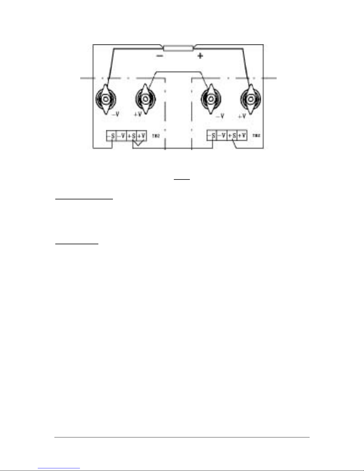
LOAD
HERCULES 1 HERCULES 2
Fig. 6
9.1 Remove Jumpers:
1.1 For HERCULES 1, Jumper between -S and –V
1.2 For HERCULES 2, jumpers between -S and -V, also between +S and +V
9.2 Connections
2.1 HERCULES 2 +V load terminal to the plus pole of load (wire with sufficient
cross section ≥ 5A/1mm²)
2.2 HERCULES 1 -V load terminal to minus pole of load (cross section ≥ 5A/1mm²)
2.3 HERCULES 2 -V load terminal to HERCULES 1 +V load terminal
(cross section ≥ 5A/1mm²)
2.4 HERCULES 2 +S to plus pole of load
2.5 HERCULES 2 -S to HERCULES 1 +S
2.6 HERCULES 1-S to minus pole of load
The output voltages are adjusted via the corresponding ‘‘VOLTAGE’’ Pots.. The total output voltage is
the sum of the two adjusted voltages. When the current limit values are not equal, the higher value
applies as valid total current limit. When one HERCULES surpasses its current limit it will deliver no
energy anymore and will have a small negative voltage (< 1V) at its load terminal.
Because none of the two HERCULES measures the total voltage, an overvoltage protection function
(OVP) is not possible. In order to obtain an even load distribution it is recommended to adjust the
‘‘VOLTAGE’’ and ‘‘CURRENT’’ control of both HERCULES in such a way that they display an equal
voltage. Devices should be switched on and off simultaneously.
Hercules 5000
Page 13 von 17 ISSUE 07/05
Page 14

10. Parallel operation
If higher output currents are required it is possible to have the ARGOS power supplies operate in a
parallel manner.
10.1 Simple output load terminals connection
Note:
In order to get an even load current distribution, both HERCULES power supplies have to be
adjusted to the same output voltage prior to connecting the output load terminals. The
connecting cables should be as short as possible and with corresponding cross section.
Because it is not possible to ensure a simultaneously switch off of the devices in case of an over
voltage, decoupling diodes should be used. In that case a sensing compensation is not possible
(see also point 8).
If an accurate regulation in necessary an Auto-Load-Share Parelling operation is to be
configured (point 10.2).
10.2 Auto-Load-Share Paralleling Operation
(only possible with supplies of same voltage and current range)
10.3 Configuration (see Fig. 7)
Select any one of the HERCULES power supplies as a master, the others (max. 3) as
slave(s).
Last
+S
-S -V
+V
-V
+V
TB4
TB3
Slave 1
+S
-S
-V
+V
-V
+V
TB4
TB3
Slave 2
+S
-S -V
+V
-V
+V
TB4
TB3
Master
100100
Fig. 7
Hercules 5000
Page 14 von 17 ISSUE 07/05
Page 15

1. Remove Jumpers:
For master HERCULES Jumpers between +S and +V, also -S and -V
2. Connections (see Fig. 7)
2.1 All HERCULES +V load terminals to the plus pole of load (with sufficient wire cross
section ≥ 5A/1mm²)
2.2 All HERCULES -V load terminals to minus-pole of load (cross section ≥ 5A/1mm²)
2.3 Master -S to minus pole of load
2.4 Master +S to plus pole of load
2.5 (TB 3 - 4) master to (TB 4 - 6) master
2.6 (TB 4 - 13) master to (TB 4 - 6) first slave
2.7 (TB 4 - 14) master with an 100Ω Resistor to (TB 4 – 8) first slave
2.8 The first slave Hercules is used as master for the second slave device and so on
2.9 (TB 4-15) of first slave to (TB 3-4) of first slaves. This one do for all slaves again.
3. Please note
3.1 All HERCULES power supplies have to be switched on and off simultaneously
3.2 In view of the stability no more than 3 slave HERCULES should be configured.
4. Operation
4.1 ‘‘VOLTAGE’’, ‘‘CURRENT’’ and ‘‘OV ADJUST’’ controls of all slaves are turned
clockwise to the maximum.
4.2 By all the slaves push the EXTERN-knob.
4.3 The desired overvoltage limit should be adjusted on the master (see chap.8)
4.4 Voltage and current limiting adjustments are performed using the master controls. The
total current limit in that case is I
lim
total = (n+1) I
lim
, n is the number of slaves and I
lim
the adjusted current limit of the master.
Hercules 5000
Page 15 von 17 ISSUE 07/05
Page 16
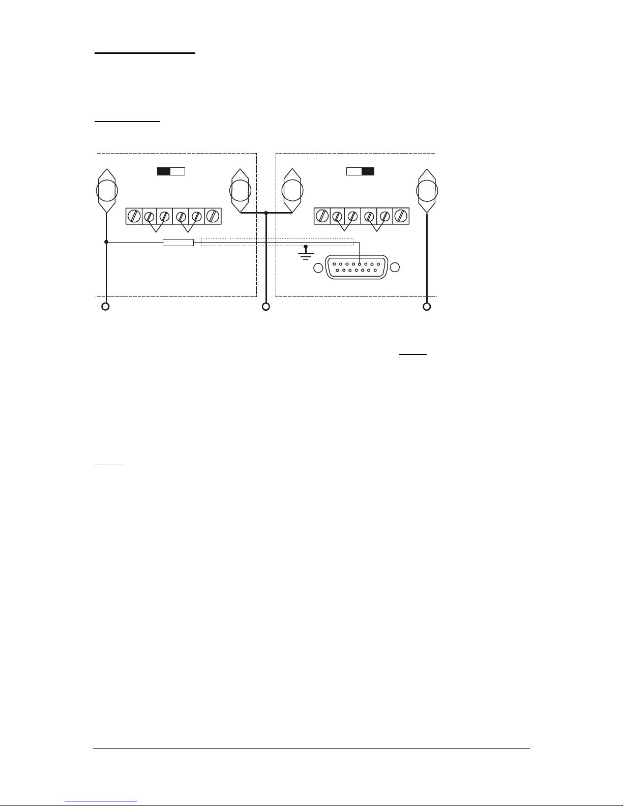
11. Tracking mode
The tracking mode permits to structure a symmetric power supply. For this two HERCULES are
necessary, the unit with negative output acts as master.
Configuration:
-V
+V
Masse
+S
-S
-V
+V
-V
+V
+S
-S
-V
+V
-V
+V
TB3
1
8
9
15
S1 S1
Master Slave
R1
Fig. 8
The resistance R1 is calculated using the following formula:
R1=(V
max
/5-1) x 20 kOhm
V
max
is the maximum output voltage in Volt of the master device.
The resistor R1 should be oversized (eg. 2W) with a Tc of ≤ 20ppm/°C.
NOTE:
a) In tracking mode the slave HERCULES is to be set in RVP mode. (S1 right, EXTERN not
pushed). However a programming resistor is not connected, consequently RVP programming is
set to zero. Because the output voltage results from the highest programmed value, the tracking
mode affects the total output voltage range.
b) The slave output voltage always results from the one of the master, independently of the
operation mode of the later, except if the current limiting or the OV protection of the slave
HERCULES is activated.
Hercules 5000
Page 16 von 17 ISSUE 07/05
Page 17

12. Monitor and status outputs
12.1 Monitor outputs
The output voltage and current can be read via two analog signals. Those signals are
proportional with the output parameters and are rated to + 10V. They are marked ‘‘V-Monitor’’
(TB 4-7) and ‘‘I-Monitor’’ (TB 4-13) and measured against TB 4-14.
Both monitor ouputs may be loaded with max. 10mA.
12.2 Status signals
Both status output are ‘‘open-collector’’ outputs, related to TB 4-8 and may be loaded with
max. 100mA. Outputs are ‘‘low’’ active. If device works in constant current mode, the CC
status output (TB 4-1) is always active. The OV status output (TB 4-2) is active if the OV
protection circuit has turned off the power supply and remains active until the OV button is
pushed or a OV-RESET signal is applied.
13. Overtemperature-protection
HERCULES is equipped with a 2 step temperature control circuit. Whenever the temperature of the
Power-Mosfet´s approx. surpasses 65°C, the fan is switched to a faster speed. If the Mosfettemperature surpasses approx. 100°C an acoustic signal is generated and the OT LED indicator
illuminates (red). Simultaneously the output power is slowly diminished. During this state only the
MOSFET’s temperature (approx. 85°C) is regulated. The LED indicators CV and CC do not light up as
ARGOS under such conditions can not full fill the specifications.
This status is not latched and after the Mosfet´s are cooled the ARGOS goes back in a normal
operation mode (CC or CV).
14. APPENDIX
Please note followings :
IEEE-488 / RS 232 INTERFACE ( OPT 34 ) Starting with Series Nr.: 907785 an automatic switching
from " INTERN " to " EXTERN " is implemented. If the BUS activates the IEEE-Interface, the
powersupply switches automatically in " Extern / Remote " mode. The command "LOCAL" switches
then automatically back to " INTERN " mode. For the RS 232 Interface the command " B1 " must be
sent in order to switch in " EXTERN / REMOTE " mode. The command " B 0 " switches back to
"INTERN" mode.
For the “IEE-488” interface, if the connection with the bus is interrupted, the power supply switches
back to “INTERN” mode. For the RS232 interface, an interruption causes no automatic switching. The
commands “B1” and “B0” may besent over the IEEE-488 bus too. If the command “B1” was sent, a
disconnection from the IEEE-488 bus will not cause automatic switching back to “INTERN”.
Hercules 5000
Page 17 von 17 ISSUE 07/05
 Loading...