

Page 1

IndustrieAlpine Allee 1
D - 94513 Schönberg
Tel.:+49 (0) 85 54/9609-0
Fax:+49 (0) 85 54/96 09 20
Mail: sales@tetelectronics.de
INSTRUCTION MANUAL
ATLAS-2000
High-performance power supplies
Atlas 2000
Page 1 von 26 ISSUE 07/05
Page 2

Inspection on receival:
All TET instruments are not cleared for dispatching until having successfully concluded
exhaustive function testing (as documented by a detailed test report). 8 hours continous
operation under worst-case conditions followed by final inspection.
It is however, good practice, to check the instruments immediately on delivery and any
mechanical damage to the instruments must be reported immediately to the corresponding
carrier for his confirmation.
Guarantee:
TET provides a 2 year guarantee on 19"-rack power supplies, valid as of the date of delivery.
This guarantee does not cover mechanical damage or defects in the instrument, caused by
failure to observe the operating instructions. This guarantee also expires, should the
instrument be opened by the user.
Guarantee is generally subject to the firm terms and conditions in the confirmation of order.
Repairs:
Should the instrument be in need of repair, you are kindly requested to contact your local TET
representative. All TET after-sales facilities are dedicated to meet requirements with
minimum delay.
Users can also turn instruments directly to:
IndustrieAlpine GmbH & Co. KG
IndustrieAlpine Allee 1
D - 94513 Schönberg
Always state type of model and serial number.
Spare parts:
Spare parts should be ordered in accordance with the following arrangement:
Qty. Designation Type Item Instrument Serial-No.
3
Transistor
2N3055
Q101-Q102
Atlas 40-30
XXXXXX
Atlas 2000
Page 2 von 26 ISSUE 07/05
Page 3

CONTENTS
CHAPTER 1: Description
1.1 General
1.2 Features
1.3 Options
CHAPTER 2: Specifications
2.1 Electrical Specifications
2.2 hysical Specifications
2.3 General Specifications
2.4 Frontpanel description
2.5 Rearpanel description
CHAPTER 3: Operating Manual
3.1 Putting into operation
3.2 Constant voltage operation with current limiting
3.3 Constant current operation with voltage limiting
3.4 Remote sensing
3.5 Remote voltage programming
3.5.1 Programming by resistance (RVP)
3.5.2 Programming by voltage (VVP=5V od. 10V)
3.6 Remote current programming
3.6.1 Programming by resistance (RCP)
3.6.2 Programming by voltage (VCP=5V od. 10V)
3.7 Series operation
3.7.1 Simple connection of load terminals
3.7.2 Master-Slave-Tracking
3.8 Parallel operation
3.8.1 Simple connection of load terminals
3.8.2 Auto-Load-Share-Paralleling
3.9 Overvoltage protection
3.9.1 OV with adjustable threshold
3.9.2 Remote threshold programming
3.9.3 Delayed current limitation (C-DYN)
3.10 Output signals
3.10.1 Monitor output
3.10.2 Status signals
3.11 Remote programming by means of the IEEE-488/RS-232 interface-card
CHAPTER 4: Options (connection and operation)
4.1 Option 07: Line change to 115VAC
Atlas 2000
Page 3 von 26 ISSUE 07/05
Page 4

CHAPTER 1
1.1 General
ATLAS-power supplies are precision constant voltage or constant current sources. TET new
ATLAS-series represents the latest generation of power supplies in accordance with state-oftheart requirements. This series features excellent flexibility of application and controls
designed in function to meet particular applications. The high quality standard permits a 2
year guarantee on these instruments.
Due to the broad range of output voltages available, instruments of this series are ideally
suited for applications as laboratory power supplies, the programming capabilities of which
ensure application in almost any system. The exceptionally high regulated and stabilized
outputs make ATLAS series instruments useful as DC standards in a great many applications.
The electrical conception of these instruments i. e. initial thyristor preregulation followed by
linear main regulation - permits more or less optimum relationship of output power to
volume. All instruments are physically concepted for compatibility with 19"-rack and panel
requirements. ATLAS series instruments meet German VDE-Class-Protection-I requirements.
1.2 Features
ATLAS series power supplies are designed for constant voltage operation with adjustable
current limiting, and constant current operation with adjustable voltage limiting with
automatic crossover. Constant current operation is indicated on the front panel by the light
emitting diode. The electronic current limiting circuit ensures permanent short-circuit
protection of all instruments.
The floating output permits output voltages to be used in conjunction with other voltages as
required. High voltages however, have to be taken in consideration to eliminate possible
electrocution hazards (as governed by German VDE regulation).
Series and parallel operation of a multiple arrangement of power supplies is provided for. The
standard versions employing remote sensing , remote current and voltage programming, series
configuration for master-slave-tracking and parallel configuration for auto-load-share
paralleling, emphasizes the universal communication capabilities on these series.
The integral overvoltage protection circuit (OV) protects the instrument from error voltages
occurring both within and external. This circuit is provided as a fixed OV as standard. These
power supplies are designed for compatibility in a 19" cabinet as long as due consideration is
given to adequate forced air cooling. A fan is provided in the power supply for removing the
heat emitted by the cooling stages, the fan drawing in fresh air at the front and blowing out
the warm air through the rear panel.
A built-in transient absorber gives added protection against voltage-spikes from the load.
1.3 Options
The high flexibility of this instrument series can be further improved by including reasonably
priced optional moduls:
Option 07: 115VAC line-voltage
Option 34: Listener-talker interface card for IEEE-488 bus and RS-232 serial port. This
card can be mounted in a slot on the rear side of the ATLAS instrument by the
customer.
Option 50: Digital display for voltage and current, 7-segment LED´s, 4 digits, as
replacement for the analog meters.
Atlas 2000
Page 4 von 26 ISSUE 07/05
Page 5

CHAPTER 2
2.1 Electrical Specifications
Model
Output voltage 0-40V 0-60V 0-160V
Output current 0-50A 0-30A 0-15A
Input 230VAC +10%, 47....65Hz (Option 07 for 115 VAC ±10%)
Output floating, isolated form ground, up to 300 VDC max.
Constant voltage mode with adjustable current limiting
Regulation:
Line 0,001% or 0,5mV*) for ± 10% line change.
Load 0,001% or 0,5mV*
Recovery time:
50µs for a change of load from 50 to 100%, and regulation within 15mV.
30µs for a load change form 50 to 100%, and regulation within 50mV.
Ripple ≤ 1 mV
Stability:
0,005% or 1mV*
ambient temperature.
Storage temperature range -20....+70°C
Operating temperature range 0....+40°C (+60°C for 20% reduction of rated current).
Temperature coefficient 0,005%V rated /°C over temperature range 0....+40°C.
Short circuit protection:
Automatic current limiting adjustable from < 100mA to rated current.
Voltage adjustment range from V
Remote sensing:
Maximum drop 0,5V per leg.
Constant current mode with adjustable voltage limiting
Regulation:
Line 0,01% for ± 10% line change.
Load 0,1% + 5mA from full load to short-circuit.
Ripple 0,1% or 50 mA
Stability:
0,05% I rated for 8 hour after warm-up. Measured at constant line voltage, load and ambient
temperature.
Temperature coefficient 0,03% I rated / °C in temperature range 0...+40°C.
Voltage compliance 0V to rated output voltage.
Constant current range adjustable from < 100mA to I rated by means of current control.
*
) whichever is greater
ATLAS 40-50 ATLAS 60-30 ATLAS 160-15
) no load to full load as measured at sensing terminals.
rms
) for 8 hours after warm-up. Measured at constant line voltage, load and
0 = 0 to V rated by means of 10-turn control.
*
)
Atlas 2000
Page 5 von 26 ISSUE 07/05
Page 6

2.2 Physical specifications
Dimensions: Width x depth: 443 x 470 mm + (handle 43 mm)
Height: 178 mm
Module width x depth: 443 x 510 mm
Weight: approx. 50 Kg
2.3 General Specification
Metering: Voltmeter and amperemeter, each class accuracy 2.5
Ventilation: Two-speed fan ventilation. Cold air inlet on the front side, warm air output on
the rear side.
Front panel controls: See Fig.1
Rear panel controls: See Fig.2 and Fig.3
Line current:
Approx. 20A at 230V and full load, 2,5A at 230V and no load.
Inrush-current limiting with 5,6 Ohm.
Atlas 2000
Page 6 von 26 ISSUE 07/05
Page 7

2.4 Frontpanel layout description
17 2 3 10 9
4 5 15 1
Fig.1
1...... Power switch
2....... Voltage output display
3....... Current output display
4....... Voltage adjustment control (10-turn pot)
5....... Current adjustment control (10-turn pot)
6....... External / internal switch and external LED-indicator
7....... Remote enable indicator
8....... LED-indicator for constant voltage mode
9....... LED-indicator for constant current mode
10..... Adjustment control for the OV-protection
11..... Overvoltage reset button and overvoltage LED-indicator
12..... Current balance
13..... Delayed current limitation ON - OFF
14..... Time-adjust for delayed current limitation
15..... Test sockets for output voltage
16..... Power-ON-indicator
17..... Ventilation
Caution:
The test sockets (15) are not appropriate to source current !
12
8
6
7
13
11
14 16
Atlas 2000
Page 7 von 26 ISSUE 07/05
Page 8

2.5 Rear panel layout description
Fig.2
1....... Rear panel
2,3... Load terminals (TB2)
4...... AC input (TB1)
5....... Mechanical stress-relevement for the input cord
6....... Grounding screw
7....... Ventilation
8....... Terminal block for +/- sense and output voltage +V, -V
9....... Regulation board with TB3, TB4, S1, S2 (see Fig.3)
10..... Opt.34 Interface-card
11..... Handle
12..... Output-cover
Atlas 2000
Page 8 von 26 ISSUE 07/05
Page 9

TB3
RVP
VVP
RCP
VCP
TB4
TB3 pin-layout 15-pol. sub-D connector
TB3-1........................... SLAVE
TB3-2........................... MASTER
TB3-3........................... RCP (0-10 KOhm)
TB3-4........................... NC
TB3-5........................... NC
TB3-6........................... NC
TB3-7........................... NC
TB3-8........................... RVP (0-10 KOhm)
TB3-9........................... NC
TB3-10......................... NC
TB3-11......................... RTN
TB3-12......................... RTN
TB3-13......................... RTN
TB3-14......................... RTN
TB3-15......................... RTN
TB4 pin-layout 15-pol. sub-D connector
TB4-1........................... CC STATUS
TB4-2........................... OV STATUS
TB4-3........................... -15VCC
TB4-4........................... +15VCC
TB4-5........................... OV-PROG. (0-12V or 0-12 KOhm)
TB4-6........................... I-PROG. (0-10V or 0-5V)
TB4-7........................... V-MONITOR (0-10V)
TB4-8........................... RTN (referred to +S)
TB4-9........................... N.C.
TB4-10......................... N.C.
TB4-11......................... OV STATUS RTN
TB4-12......................... RTN
TB4-13......................... I-MONITOR (0-10V)
TB4-14......................... RTN
TB4-15......................... V-PROG. (0-10V or 0-5V)
Fig.3
Atlas 2000
Page 9 von 26 ISSUE 07/05
Page 10

Chapter 3
3.1 Putting into operation
Prior to putting the instrument into operation, a threepole power cord must be connected to
the power barrier strip 'TB1' on the rear panel. The gauge of the power cord is to be selected
so, that the cord can carry 20A at 230V or 40A at 115V.
The phase (Ph) and common (N) are connected to the AC-AC terminals (TB1-1 and 3).
Ground (E) is wired to the terminal G (TB1-2) or the grounding screw. As soon as the the
power switch is positioned 'ON', the instrument is ready for operation. The warm-up time
required to achieve the stability specification being negligible at room temperature.
Note: The outputs of the power source should not be connected to AC- sources, DC- sources
with reverse polarity or DC-sources with higher voltage than 1.2 x U
mode is inevitable (e.g. charging batteries, paralleling power sources or working with heavy
inductive loads), the customer must assure proper safety measures ( e.g. OR-ing diodes, fuses
etc.).
nominal If such an operating
3.2 Constant voltage operation with current limiting
This mode of operation is reached, when the LED-indicator 'CV' lights up. Because of the
high stability of ATLAS, it is possible to adjust accurately the output voltage to several
decades. For this, an adequate digital voltmeter should be used. The local adjustment is
performed using the voltage control knob 'VOLTAGE'.
The adjustment to the desired and limited current is achieved by short-circuiting the output
and using the current limiting control knob while reading the display.
3.3 Constant current operation with voltage limiting
This mode of operation is reached when the LED-indicator 'CC' lights up. The hight of the
constant current is locally adjusted using the current control knob 'CURRENT'. The lower
limit for the constant current operation is 100mA. It is important to be careful, particularly
when working with small output currents, since the charging or discharging currents of the
output capacitor affects the constant current, depending on the charging condition of the
output capacitor under dynamic loading condition.
The output voltage to be maximum limited is adjusted by using the voltage control knob and
reading the display.
3.4 Remote sensing
Unavoidable voltage drops across the output terminals and the load lines can be compensated
by including sensing leads in conjunction with the load. Noting however, that a voltage drop
of 0,5V for each lead must not be exceeded.
Circuit arrangement:
1. Open links between +V and +S, -V and -S respectively.
2. Connect the load (±V), and sensing (±S) leads, and connect them to the load
connections (same polarities together).
Note:
When operating the power supply with the sensing leads opened or interrupted, rated data can
no longer be maintained. However, instruments are protected so that no damage can be result
even
with an S-lead open.
Atlas 2000
Page 10 von 26 ISSUE 07/05
Page 11

When using long sensing leads, it is good practice to screen cables and to provide the
blocking capacitors, as shown in Fig.4, connected to the instruments terminals.
With sensing leads connected but load leads interrupted, a protection circuitry will inhibit
both pre-regulator and series-regulator. This mode is latched and can be reset only switching
the power supply OFF and ON again.
Terminal-block links from factory:
+V +S –S –V
Load
Fig.4 (rear panel partial view)
3.5 Remote voltage programming
1. The output voltage can be adjusted by means of a remote programming resistance or
a remote programming voltage.
2. When using long programming leads, it is a good practice to screen the wires, to
prevent pickup disturbances. If the instrument tends to oscillate, due to the inductivity
of the long programming line, users are recommended to apply blocking capacitors
across the programming terminals.
3. Programming speed:
Speed at which the output voltage responds to a change of adjustment depends on the
parameters load impedance, output capacity, programming element response, direction
and amount of change. Response can thus vary depending on individual parameters.
The fastest output voltage response is between 200 and 400ms for a programming step
of 100% and depending on the type of power supply.
Atlas 2000
Page 11 von 26 ISSUE 07/05
Page 12

3.5.1 Resistance voltage programming (RVP)
↑
Configuration:
1. Push the 'EXTERN' knob on the front and switch 'S1' upwards.
2. Connect the programming resistance between TB3-8 and TB3-15
Note:
1. The output voltage will be proportional to the programming resistance. For
10KOhm the output has nominal value. To avoid stability errors, the resistor should
feature a temperature coefficient of 20ppm/°C and sized >0,5W.
TB3
Meaningless for RVP
-
RVP
0...10kOhm
-
Fig.5
2. A resistance over 12KOhms (e.g. open leads) will block the series-regulator and the
preregulator.
3. With the 'EXTERN' knob pushed, the output current too has to be programmed
(RCP or VCP, see chapter 3.6.1 and 3.6.2).
3.5.2 Voltage voltage programming (VVP) (VPROG = 5V or 10V)
Configuration:
1. Push the 'EXTERN' knob on the front and switch 'S1' downwards.
2. Connect:
Negative from the programming voltage to TB4-8.
Positive from the programming voltage to TB4-15.
Note:
The Instruments are factory-preset for 10V programming. For 5V programming pull
the regulation board from the power supply, short the jumper 'J301' (see last page),
push the regulation board back on it´s place.
Atlas 2000
Page 12 von 26 ISSUE 07/05
Page 13

Operation:
↓
1. Switch on power supply
2. Switch on the programming voltage
3. The output voltage will be proportional to the
programming voltage. For 10V (5V) programming
voltage the output has nominal value.
Note:
1. Stability, ripple and thermal-coefficient are now a
function of the programming source.
2. With the 'EXTERN' knob pushed, the output current
too has to be programmed (RCP or VCP, see chapter
3.6.1 and 3.6.2)
VVP
0...10V
0....5V
-
-
=
+
-
Fig.6
TB3
(meaningless for VVP)
TB4
Atlas 2000
Page 13 von 26 ISSUE 07/05
Page 14

3.6 Remote current programming
↑
1. The output current can be adjusted by means of a remote programming resistance or
a remote programming voltage.
2. When using long programming leads, use the same precautions as for remote
voltage programming ( see chapter 3.5)
3.61 Resistance current programming (RCP)
Configuration:
1. Push the 'EXTERN' knob on the front and switch 'S2' upwards.
2. Connect the programming resistance between TB3-3 and TB3-11 (see fig.7 )
Note:
1. The output current will be proportional to the programming resistance. For
10KOhm the output has nominal value. To avoid stability errors, the resistor should
feature a temperature coefficient of 20ppm/°C and sized > 0,5W.
2. A resistance over 12KOhms (e.g. open leads) will block the series-regulator and the
preregulator.
3. With the 'EXTERN' knob pushed, the output voltage too has to be programmed
(RVP or VVP, see chapter 3.5.1 and 3.5.2).
RCP
0...10kOhm
TB3-3
TB3-11
Fig.7
(meaningless for RPC)
TB3
Atlas 2000
Page 14 von 26 ISSUE 07/05
Page 15

3.6.2 Voltage current programming (VVP) (VPROG = 5V or 10V)
↓
Configuration:
1. Push the 'EXTERN' knob on the front and switch 'S2' downwards.
2. Connect: Negative from the programming voltage to TB4-8.
Positive from the programming voltage to TB4-6
Note:
The intruments are factory-preset for 10V programming. For 5V programming pull the
regulation board from the power supply, short the jumper 'J302' (see last page), push the
regulation board back on it´s place.
Operation:
1. Switch on power supply.
2. Switch on the programming voltage.
3. The output voltage will be proportional to the programming voltage. For 10V (5V)
programming voltage the output has nominal value.
Note:
1. Stability, ripple and thermal-coefficient are
now a function of the programming source.
2. With the 'EXTERN' knob pushed, the output
voltage too has to be programmed (RVP or VVP,
see chapter 3.5.1 and 3.5.2).
VCP
0...10V
0....5V
=
TB3
(meaningless for VCP)
-
-
+
-
Fig.8
TB4
Atlas 2000
Page 15 von 26 ISSUE 07/05
Page 16
3.7 Series operation
V
3.7.1 Series operation by simply connecting the output terminals
Series operation of ATLAS power supplies enable a higher output voltage, however the total
output voltage should not exceed 300V. Besides it is to be noted that a voltage drop due to the
connecting lines is generated according to the current load. For an accurate regulation the
following configuration is to be respected.
+ Load -
+V
Open:
1. Link between +S and +V by ATLAS 1
2. Links between +S and +V and -S and -V by ATLAS 2
Connect:
1. +V load terminal from ATLAS 1 to the plus-pole of load (wire with sufficient cross section
> = 5A/mm²).
2. -V load terminal from ATLAS 2 to the minus-pole of load (cross section > = 5A/mm²).
. -V load terminal from ATLAS 1 to +V load terminal from ATLAS 1 (cross section > =
5A/mm²).
4. +S from ATLAS 1 to the plus-pole of load.
5. -S from ATLAS 1 to +S from ATLAS 2
6. -S from ATLAS 2 to the minus-pole of load.
ATLAS 1
-
+V
-V
ATLAS 2
Fig. 9
Atlas 2000
Page 16 von 26 ISSUE 07/05
Page 17

The output voltages are adjusted via the corresponding VOLTAGE- potentiometer. The total
output voltage is the sum of the two adjusted voltages. The two units may be programmed in
different manner (e.g. unit 1 in RVP, unit 2 in VVP). If the current-limits are not equal, the
lower current-limit will be efficient.
Because none of the two ATLAS measures the total voltage, an overvoltage protection
function
(OVP) is not possible. In order to obtain an even load distribution it is recommended, to
adjust the 'VOLTAGE' and 'CURRENT' control of both ATLAS in such a way that they
display an equal voltage. Devices should be switched on and off simultaneously.
3.7.2 Series operation in Master-Slave-Tracking mode
The tracking mode permits to structure a symmetric power supply. For this, two ATLAS units
are necessary, the units with positive output acts as master. The configuration is given in
fig.10.
Open:
1. Links between +S and +V and -S and -V from master.
2. Links between +S and +V and - S and -V from slave.
Connect:
1. +V load terminal from master to the plus-pole of load.
2. - V load terminal from slave to minus-pole of load.
3. -V load terminal from master to the common of load.
4. +V load terminal from slave to the common of load.
(above four connections with sufficient cross section > = 5A/mm²)
5. +S from master to the plus-pole of load.
6. -S from master to the common of load.
7. +S form slave to - S from master.
8. Between +S from master and +S from slave two resistors in series (R1, R2, see fig.10).
They should have a temperature coefficient of less than 20ppm/°C and should be
oversized (> 2W), in order to avoid stability faults. R1 should have a value between
1Kohm and 10KOhm, R2 is given by the formula from fig.10.
9. The common from R1 and R2 to TB4-15 from slave.
10. A 10KOhm resistor between TB3-3 and TB3-11 (see chapt. 3.6.1). The slave must operate
in 'VVP' (10V) for voltage and 'RCP' for current: 'EXTERN' knob pushed, 'S1' downwards,
'S2' upwards. The master can be programmed in any allowed way.
Atlas 2000
Page 17 von 26 ISSUE 07/05
Page 18

EXTERN-knop on front
side pushed
R2 = R1 x (U
U
= Nominal voltage from master in volts
max
– 10) /10
max
Fig.10
Note:
In the configuration shown in fig.10, the currents flowing through +R load and -R load must
not be equal. The master can limit only the current through +R load. The current limit from
slave can be set with a resistance (< 10KOhms), connected between TB3-3 and TB3-11 (see
chapt 3.6.1). Power must be switched on and off simultaneously on both units.
Atlas 2000
Page 18 von 26 ISSUE 07/05
Page 19

3.8 Parallel operation
If higher output currents are required, it is possible to have the ATLAS power supplies
operate in a parallel manner.
3.8.1 Simple output load terminals connection
In order to get an even load current distribution, both ATLAS power supplies have to be
adjusted to the same output voltage prior to connecting the output load terminals. The
connecting cables should be as short as possible and with corresponding cross section.
Protection diodes (redundant diodes, 'or-ing' diodes) are not necessary. Power must be
switched on and off simultaneously on both units.
If an accurate regulation is necessary, an auto-load-share paralleling-operation is to be
configured.
3.8.2 Auto-load share-paralleling
Configuration:
Choose one ATLAS as master, the other (others, max. 3) as slave (slaves) (see fig. 11).
Open on the slave (slaves):
1. The jumper 'J304' on the regulation board. Pull the board from the unit, remove the
jumper, push the board back into the unit.
2. The links between +V and +S and -V and –S
Connect:
1. +V load terminal(s) form slave(s) to +V load terminal from master; +V load
terminal from master to the plus-pole of load.
2. -V load terminal(s) from slave(s) to -V load terminal from master; -V load terminal
from master to the minus-pole of load. All above connections with sufficient crosssection (>= 5A mm²).
3. +S from slave(s) to +S from master (0,25mm²).
4. -S from slave(s) to -S from master (0,25mm²).
5. TB3-1 from slave(s) to TB3-1 from master (0,25mm²).
Operation:
1. On the slave(s) turn the 'voltage' and 'current' potentiometers full clockwise (max.).
2. Voltage and current can be adjusted from the master.
3. Connect the load.
4. If necessary, adjust equal currents on the units by means of the 'current-balance'
(C-BAL) potentiometer.
Note:
Power must be switched on and off simultaneously on all units.
Atlas 2000
Page 19 von 26 ISSUE 07/05
Page 20

Remove jumper “J304” on the
Atlas 2000
Page 20 von 26 ISSUE 07/05
Fig. 11
Regulation board (see last page)
Page 21

3.9 Overvoltage protection
3.9.1 Internal programming of the overvoltage-threshold
Adjusting the threshold:
1. Turn, by means of a small srewdriver, the 'OV-ADJ' potentiometer full clockwise.
2. Turn on the unit and adjust the output voltage on the value of the desired threshold.
Should this value be higher then the nominal voltage, use a short-protected, floating
external DC-supply with sufficient voltage and connect it directly on the output load
terminals. The threshold should be at least 0,5V higher than the desired working
voltage.
3. Turn the 'OV-ADJ' potentiometer slowly counter-clockwise, until the protection
trips.
4. Is the overvoltage –threshold on work (red 0V – LED is lightning), turn the power
of the supply off and turn it again on about 5 secounds later.
Caution:
OV –potentiometer at frontpanel is turned full right means an output voltage about
20% over U
rated
3.9.2 Remote programming of the overvoltage-threshold
The threshold can be programmed by means of a remote programming resistance or voltage
(see fig. 12).
Configuration:
The programming voltage should be connected with it´s negative on TB4-12, it´s positive on
TB4-5. The programming voltage should take values between zero and 12V, the threshold
will be proportional to the programming voltage. For 12V the threshold will be 120% from
the nominal output voltage. Instead of a programming voltage, a programming resistance can
be connected on the same terminals, TB4-5 and TB4-12. It should have a low temperature
coefficient (< 50ppm/°C) and oversized (< 0,5W). It´s value can vary between 0KOhm and
12KOhm.
The threshold is proportional to the resistance. For 12KOhm the threshold will be 120% from
the nominal output voltage.
Atlas 2000
Page 21 von 26 ISSUE 07/05
Page 22

Fig. 12
Note:
The remote-programmed threshold and the one adjusted by means of the 'OV-ADJ'
potentiometer, are members in a minimum function, it acts always the smaller valule. In this
minimum function automatically will be considererd the threshold programmed via the
Opt.34- board (Interface-card) too, if the Opt.34-board is activated.
If the programming voltage can not sink current, a 100 Ohm/0,5W resistor should be
connected parallel to the source.
+
=
-
100Ohm
(see note)
S1 and S2 with no
meaning
TB4
Atlas 2000
Page 22 von 26 ISSUE 07/05
Page 23

3.9.3 Delayed current limiting.
The load can draw from the power supplies ATLAS an overcurrent (150% from the actual
current limit, I
limited to the currrent limit. Every overcurrent period is followed by a relaxtion-time, approx.
10 times longer than the overcurrent-time, in which no overcurrent can be delivered (see
diagram in fig. 13).
Note:
The dalay-circuit will be activated only by driving the power supply in current-limiting,
indicated by the yellow LED 'CC'.
Adjusting the delayed current limiting:
1. Connect to the outputs a resistive load (> 150% I
correspondingly sized shunt. With an oscilloscope you can monitor the time-diagram.
2. Disconnect the load, adjust the trimmer 'TIME' to approx. central postition.
3. After connecting the load, the output current will rise up to 150% from the actual
current limit, I
4. The time-span for the overcurrent is 5ms to 500ms, and can be adjusted from the
trimmer 'TIME' on the front panel.
5. Relaxion-time = 10 x overcurrent-time
SET) for a period not exceeding 500ms. After the delay-time, the current will be
SET) and in series with the load a
SET. After a few hundred milliseconds falls it back to ISET.
Fig.13
Atlas 2000
Page 23 von 26 ISSUE 07/05
Page 24

3.10 Monitor and status outputs
3.10.1 Monitor outputs
The output voltage and current can be read via two analog signals. These signals are
proportional with the output parameters and are rated to +10V. They are marked 'V-Monitor '
(TB4-7) and 'I-Monitor ' (TB4-13), and measured against TB4-14. Both monitor outputs may
be loaded with max. 10mA.
3.10.2 Status signals
Both status outputs are 'open-collector-outputs', related to TB4-8 and may be loaded with
max. 100mA. Outputs are low-active. If device works in constant current mode, the CCstatus-output (TB4-1) is always active.
The overvoltage-status (TB4-2, TB4-11) will be activated, when the overvoltage-protection
trips. It is a floating NPN-Transistor form an optocoupler, TB4-2 is the collector, TB4-11 is
the emitter. Absolute limits are: V
Note:
In instruments equipped with Opt.34 interface-card are the OV-status-outputs loaded by the
interface and they are not allowed to be used externally.
3.11 Remote programming by means of the IEEE-488/RS-232 interface-
card (Opt.34)
For a complete description of the interface-card, consult the manual. There only aspects
typical for ATLAS will be described.
If the IEEE-488 port receives a valid command, the power supply will switch automatically in
'EXTERN/Interface' mode. In this mode are all programming possibilities ineffective, only
the overvoltage threshold can be programmed (by means of the 'OV-ADJ' trimmer or remote)
lower than the value programmed on the BUS. This working-mode can be abandoned with the
command 'LOCAL'.
Using the RS-232 (serial) port, the automatic switchover will be activated with the command
'B1', to abandon, send 'B0'. The digital outputs of the card are not used, digital input 'DINP1'
reads the OV-status, ' DINP2' reads the CC-status, ' DINP3' is not used.
CE = 35V and IC = 20mA.
Atlas 2000
Page 24 von 26 ISSUE 07/05
Page 25

CHAPTER 4 (Options)
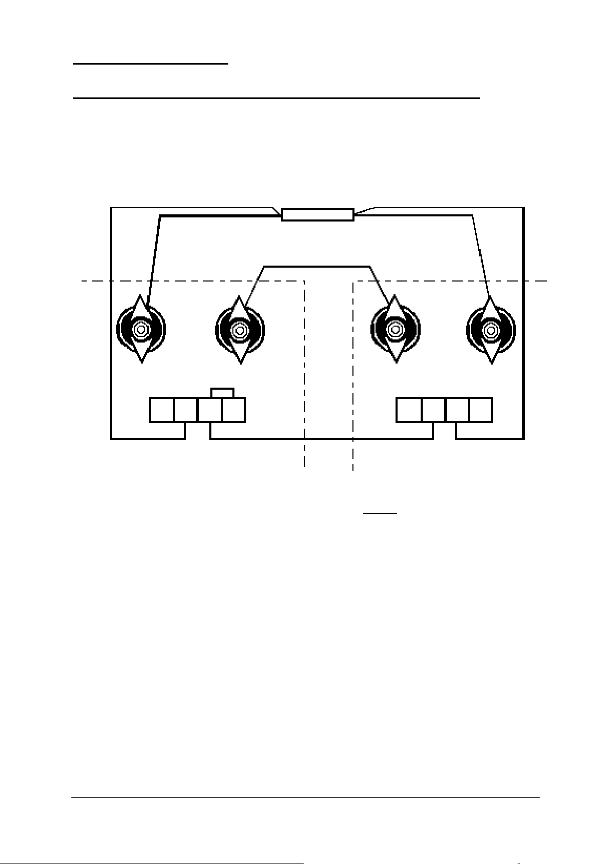
4.1 Option 07: 115 VAC line connection (see Fig. 14)
1. Option 07 power supplies are delivered for 115 VAC line voltage.
2. Switching from 115 VAC to 230 VAC
a) Remove the links connecting terminals 1-21 and 2-22 on the power transformator T101.
Connect the jumper J3 on transformer T101 between terminal 21-22.
b) Remove on the power switch the jumper J1 and J2
c) Note: In the unit for 115 VAC the OV-funktion is clamping.
To reset the OV, turn the line switch off and on again.
Fig. 14
Atlas 2000
Page 25 von 26 ISSUE 07/05
Page 26

r
r
Remove by Slaves
(see page 20)
U-max
(Opt.34)
U-Monito
I-Monito
I-max I-min
U-min
(Opt.34)
RVP
VVP 5V or 10V
(see page 15)
VVP 5V or 10V
(see page 12)
Atlas 2000
Page 26 von 26 ISSUE 07/05
 Loading...