

Page 1
Validator-NT
NETWORK/CABLING CERTIFIER
OPERATING INSTRUCTIONS
TM
Validator NT955
Page 2
6
MNO
JKL
5
4
GHI
*
7
PRS
0
#
9
TUV
8
QZ
WXY
M
E
N
U
1
A
C
C
P
T
T
E
S
T
3
ABC
2
DEF
SEL
Q
U
I
T
Test Results
Untitled1.job
50%
Test-Um Inc.
validator
2004 Oct11
10:53:01
Expected
Results
1 1
2 2
3 3
6 6
4 4
5 5
7 7
8 8
Cable001
Pass
1 1
2 2
3 3
6 6
4 4
5 5
7 7
8 8
Test Time: 10/11/2004 10:53 A.M
Test Results
PASS
VALIDATOR-NT
TM
CONTEXT
SENSITIVE
KEYPAD
SELECT
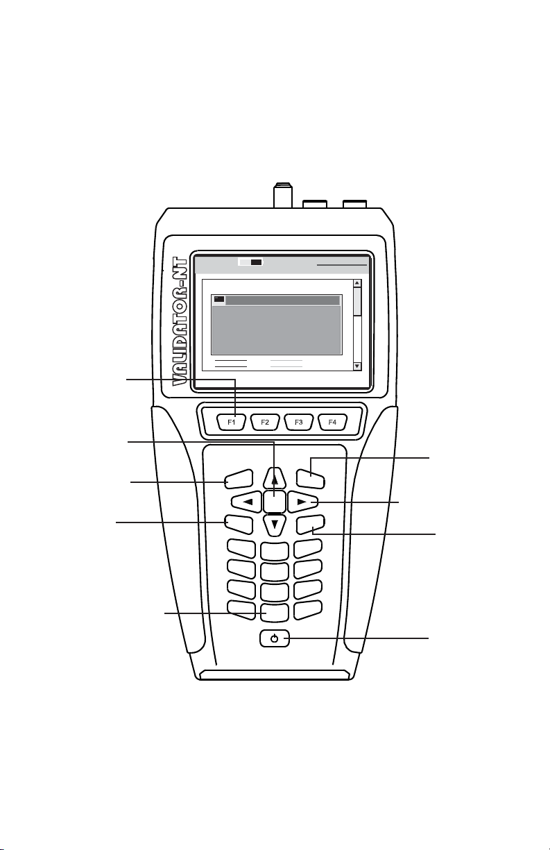
ACCEPT
MENU
ALPHANUMERIC
KEYPAD
QUIT
NAVIGATION KEYS
TEST
POWER
Page 3

Congratulations!
You have just purchased the world’s most advanced Speed and
Performance Certier. Your Validator-NT is designed to give you years of
reliable service with reasonable care. Remember these important Care
Points.
• Re-charge the lithium-ion batteries nightly. Lithium-ion batteries
like to be charged overnight. They do not have “memory”
problems like older battery technology and are smart enough
to know when they are full. Make sure you start your job with
enough battery power to nish it.
• Keep your Validator-NT clean with a damp soft cloth. Using
cleaning agents can damage the poly carbonate lens over the
LCD screen
• Clean spills and moisture from the Validator-NT immediately. Do
not allow the Validator-NT to be submerged. Battery and display
damage will result.
• Use the RJ45 Sacricial Cable Modules (TP74) provided with
the NT955 kit to prolong the life of your RJ45 data jack on your
Validator-NT main and remote unit. Replace these as necessary.
• Remember to register your Validator-NT online immediately. You
must register your product at www.test-um.com to download
rmware and software updates and obtain access to other
valuable support tools available on our web site. If you prefer,
you may ll out the enclosed warranty registration card and mail
it in.
Above all, enjoy your new Validator-NT. It will make your testing life
easier.
Page 4

TABLE OF CONTENTS
Introduction ........................................................................ 5
Ethernet Cable Certication .............................................................. 6
Active Network Features ................................................................... 7
Plan-Um
Test Ports and Cable Adapters ......................................................... 8
Registration ..................................................................................... 12
Support Information ......................................................................... 13
Tests Performed .............................................................................. 14
TM
Software .......................................................................... 7
About Your Validator-NT ................................................. 15
Main Unit Features .......................................................................... 15
Remote Unit Features ..................................................................... 18
Standard Accessories ..................................................................... 20
Optional Accessories ....................................................................... 21
Menu Options & Navigation ............................................................ 22
Battery and Power Management .................................... 23
Battery Lock Feature ....................................................................... 26
Operations ........................................................................ 27
1. Setting Up the Test Tool .............................................. 29
1.1. Display Contrast ....................................................................... 30
1.2. Printer Settings ......................................................................... 31
1.3. Shutdown Timeouts .................................................................. 32
1.4. Set the Clock using the Real Time Clock Screen ..................... 33
1.5. Localization ............................................................................. 34
1.6. Calibrate .................................................................................. 35
2. Validator-NT Properties ............................................... 36
2.1. Battery Info ............................................................................... 37
2.2. Product Version ........................................................................ 39
2.3. Compact Flash Card Usage ..................................................... 40
2.4. Support Info ............................................................................. 41
3. Managing Job Files ..................................................... 43
3.1. Creating A New Job .................................................................. 46
3.2. Creating Job Information .......................................................... 47
3.3. Creating Template Information ................................................. 48
3.4. Using Template Files ................................................................ 49
3.5. Step By Step Instructions for Creating a New Job ................... 50
Page 5

TABLE OF CONTENTS
4. How Auto Test Works .................................................. 52
4.1. Cable Test Schedule ................................................................ 54
4.2. Site Info .................................................................................... 58
4.3. Contractor Info ......................................................................... 58
4.4. Custom Cable Denitions ......................................................... 59
4.5. Job Utilities .............................................................................. 62
4.6. Step by Step Instructions for Performing Auto Tests ............... 63
5. Running Manual Tests ................................................. 65
5.1. Data Cables ............................................................................. 65
5.2. Phone Cables ........................................................................... 67
5.3. 2-Wire Cables .......................................................................... 68
5.4. Step by Step Instructions for Performing Manual Tests ........... 69
6. Performing Active Network Tests ............................... 74
6.1. Port Discovery ........................................................................ 75
6.2. Ping Test .................................................................................. 79
6.3. Cisco Discovery Protocol ......................................................... 84
6.4. Hub Flash ................................................................................ 87
6.4. Step by Step Instructions for Performing Network Tests .......... 88
7. Uploading/Downloading Jobs .................................... 91
7.1. Uploading the Cable Test Schedule to the Validator-NT .......... 91
7.2. Downloading Test Results from Validator-NT to Plan-Um ........ 92
8. Archiving/Saving Test Results ................................... 93
9. Printing Test Results ................................................... 94
10. Application Notes for Typical Field Use ....................95
10.1. New Job, New Cable Installations .......................................... 95
10.2. New Job, Previously Installed Cables .................................... 95
10.3. Existing Job, Adds, Moves and Changes .............................. 96
Page 6

Test-Um NT955 Series
ValidatorTM IntroductionValidatorTM Introduction
Introduction
The Validator-NT (NT955) Certier uses Speed and Performance
criteria to test and certify Ethernet network cables against IEEE802.3
specications up to 1 Gigabit. It also tests critical noise and delay
(Skew) measurements to assure that the respective cable runs will
perform to their maximum capability. Breakthrough technology has made
Speed and Performance Certication possible. It is the most up to
date way of seeing the physical condition of the wiring and how a specic
cable run will handle data ow on Ethernet speeds, 10 Megabit, 100
Megabit and Gigabit.
In addition to its state of the art 21st Century cable certication
technology, Validator-NT boasts a full selection of active network features
designed to report cable performance and verify connectivity to network
devices. These features include the ability to negotiate with network
components and discover both the speed and conguration of connected
equipment.
5
Page 7

Test-Um NT955 Series
Ethernet Cable Certication
Speed and Performance Certication uses digital technology centered on
the latest advances in Gigabit Ethernet Transceivers. These new highly
integrated chips are capable of testing for noise in the network, faults in
the cabling wiring and even generating live data packets that stress the
cables to make sure they are able to support the equipment connected to
them. This is the heart of the Validator-NT Certier.
To do Speed and Performance Certication Validator-NT measures
three specic levels of cable and connector conditions. Unless all three
of these levels are tested it is impossible to accurately determine a cable
run’s capability.
1. Measure TIA 568 Interconnect Specications such as Opens,
Shorts, Miswires, Split Pairs and Reversals. The distance to
faults and length of cable runs are accurately pinpointed with
the use of both TDR and capacitance length measurement
techniques. The Validator-NT measures length up to a maximum
of 1500 feet or 457 meters.
2. Measure Pertinent Parameters of Noise and propagation delay.
NEXT, Return Loss, Attenuation, Amplitude and other noise
factors are tested using Signal to Noise Ratio measurements.
SKEW is measured using TDR (Time Domain Reectometry) to
insure acceptable signal time delay differences between pairs for
Gigabit use.
3. Conduct a Bit Error Rate Test. BERT sends actual data
packets down specied cable runs at dened data rates and
quantities. Random code data is generated and checked for
errors at the maximum throughput of the link, full duplex.
ValidatorTM IntroductionValidatorTM Introduction
6
Page 8

Test-Um NT955 Series
ValidatorTM IntroductionValidatorTM Introduction
Active Network Features
Validator-NT includes three functional test areas that are designed to
report cable performance and verify connectivity to network devices.
They are Port Discovery, Ping, and Hub Flash.
Port Discovery identies telephone or network devices connected to the
other end of the jack or cable.
A Ping Test veries connectivity to resources on or off the network
and IP addresses. The Ping Test will simultaneously Ping up to seven
different IP addresses and can be run in DHCP or manual addressing
modes.
Cisco Delivery Protocol detects messages broadcast by Cisco bridges
and routers over the network to inform each other of their existence.
Hub Flash sends an intermittent link signal to ash the link status light
on Ethernet equipment.
Plan-Um
TM
Software
If the heart of Validator-NT is a Gigabit Ethernet Transceiver then the
soul of the Validator-NT is the powerful planning and reporting software
included in your test kit, Plan-Um. Plan-Um software ties the superior
testing capability of the Validator-NT with a simple to use software tool
that helps organize the cable information and test results associated with
your jobs.
Plan-Um will help set up each job, dene the scope of the job, aid in
testing the individual cable runs accurately and produce an End of Job
report that will tie in all the expectations of the installer and the customer.
The Network Tools feature in Plan-Um allows you to quickly and easily
create a topological representation of your physical network, annotate
each piece of equipment, and characterize the connection methods.
This feature is completely separate from the layout of the cable runs and
the Cable Test Schedule. It provides a quick way to see the architecture
of your network and a way to document moves, adds, and changes in an
organized and effective manner.
Validator-NT and the Plan-Um software combine to close the loop on
cable/network installations so that both the network user and the network
installer can be condent of the physical properties of specic cable runs
and the overall capability of the network in general.
7
Page 9

Test-Um NT955 Series
Test Ports and Cable Adapters
Validator-NT is equipped with four dedicated ports for testing data,
telephone, coax, and 2-wire cable types.
Data Jack RJ45 8-wire data interface
Telephone Jack RJ11, 6-wire Telco interface
USOC pairing
Coaxial Connector “F” connector coax interface
Banana Jacks 2-wire testing
The Validator-NT test kit is supplied with ve cable assemblies designed
to connect to the data, telephone, coax, and 2-wire ports of the main or
remote Validator-NT units. A set of 8 wiremap remotes (TP610) are also
included in this test kit.
TP74 4” sacricial cable with RJ45 connectors
TP20 7.5” no fault cable assembly with RJ11
connectors for the RJ11 or RJ45 port
TP55 12” shielded cable assembly with RJ45 connectors
ValidatorTM IntroductionValidatorTM Introduction
TP68 24” cable assembly with an RJ45 connector and 8
alligator clips
TP62 Adapter, BNC plug to F jack
Note: It is recommended that you leave the TP74 Sacricial Cables
connected to prolong the life of the RJ45 network cable port of your
Validator-NT main and remote unit.
8
Page 10
Test-Um NT955 Series
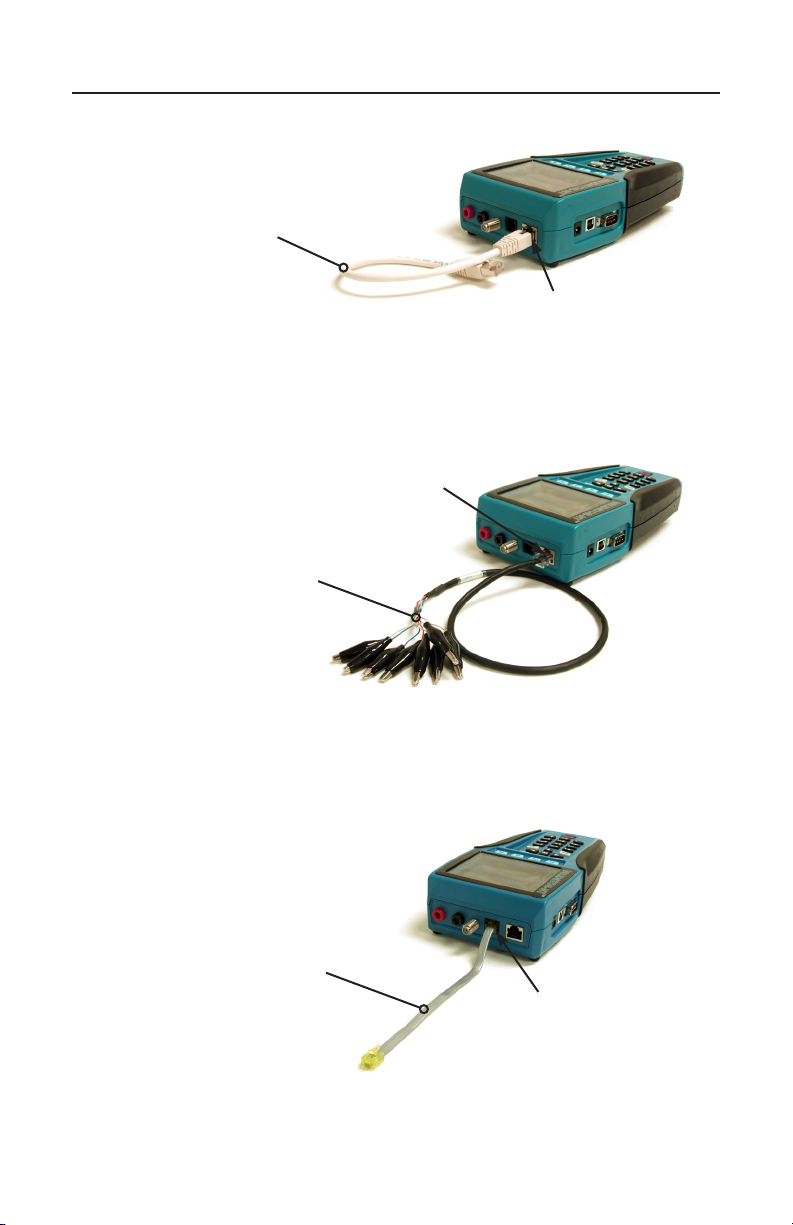
Data Cables and Connection
12” shielded cable
assembly with RJ45
connectors
(TP55)
Figure 1. TP55 Connected to Validator-NT
RJ45 8-wire data
interface
24” cable assembly with
an RJ45 connector and
8 alligator clips
(TP68)
ValidatorTM IntroductionValidatorTM Introduction
RJ45 8-wire data
interface
Figure 2. TP68 Connected to Validator-NT
Telephone Cable and Connection
7.5” no fault cable
assembly with RJ12
connectors for the RJ11
or RJ45 port
(TP20)
Figure 3. TP20 Connected to Validator-NT
RJ11, 6-wires
Telco interface
USOC pairing
(TP20)
9
Page 11
Test-Um NT955 Series
Two Wire and Connections
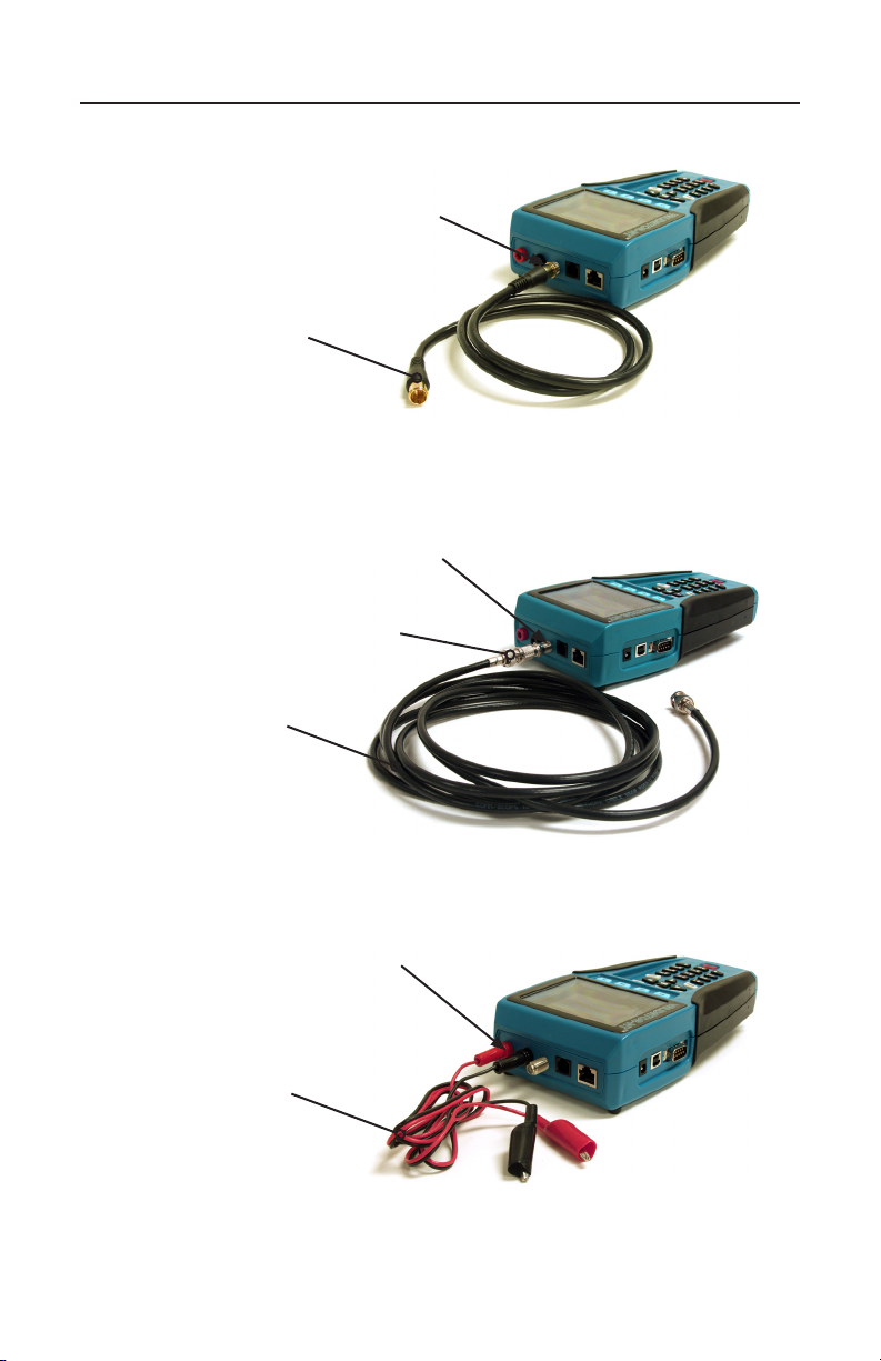
“F” connector coax
interface
3’ RG6 video
coaxial cable
(not included)
Figure 4. Video Coaxial Cable Connected to Validator-NT
“F” connector
coax interface
Adapter, BNC plug to F Jack
(TP62)
RG59/U Coaxial
cable with BNC
connectors (not
included)
ValidatorTM IntroductionValidatorTM Introduction
Figure 5. Security Cable Connected to Validator-NT
Banana Jacks
2-wire testing
Banana Jacks to alligator
clip cable assembly
(not included)
Figure 6. Banana Jack Cables Connected to Validator-NT
10
Page 12
Test-Um NT955 Series
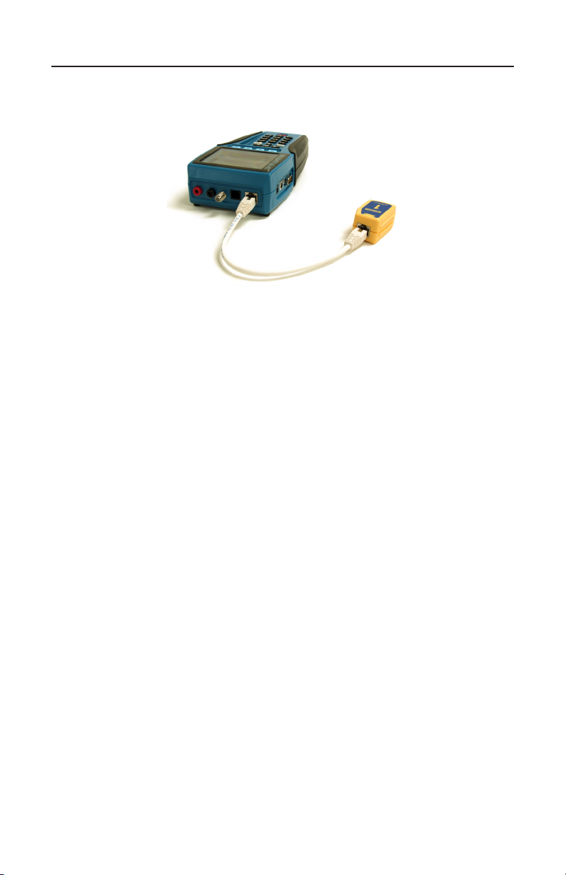
Data Cable & Remote Connection
Figure 7. Wiremapper Remote #1 Connected to Validator-NT
ValidatorTM IntroductionValidatorTM Introduction
11
Page 13
Test-Um NT955 Series
Registration
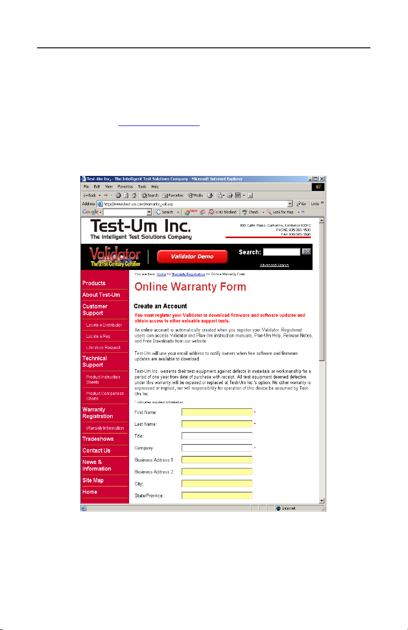
You must register your product with Test-Um Inc. to be eligible to
receive rmware and software updates, as well as important product
announcements, helpful hints and other support services. To register, go
to our web site at www.test-um.com and click on Warranty Registration
or ll out the enclosed warranty registration card completely and mail it
immediately.
ValidatorTM IntroductionValidatorTM Introduction
12
Page 14

Test-Um NT955 Series
Support Information
Post-sale Technical support is available Monday through Friday 8:30
am to 4:30 p.m. Online technical assistance is available via our web site
at www.test-um.com by selecting Validator-NT from the Home screen
and clicking Contact Us. You may send e-mail to [email protected]
or click Live Chat to communicate real time with our Technical Support
department via instant messaging. To get the location of the nearest
Test-Um distributor, go to the web site or call (805) 383-1500.
Accessing the Technical Reference Manual
The NT955 Operating Instructions are available at www.test-um.com. As
product updates are released, revisions to the instructions will be posted
to our web site.
ValidatorTM IntroductionValidatorTM Introduction
13
Page 15
Test-Um NT955 Series
Tests Performed
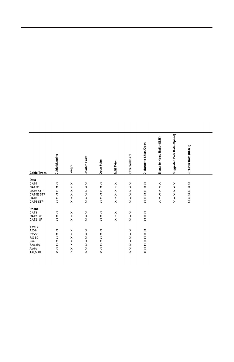
Validator-NT performs specied tests that produce PASS or FAIL results
on a wide range of standard cables. In addition, a Bit Error Rate Test
(BERT) is performed to determine the actual speed capabilities of CAT
5, CAT 5E, and CAT 6 network cables. A green check mark with VoIP
indicates the cable is certied to support a data rate of 100 Megabit or
greater, which is a basic requirement for VoIP applications.
The following chart species the pre programmed tests that are
performed on specic cable types (see gure 7).
Figure 7. Pre programmed Auto Tests for Specic Cable Types
ValidatorTM IntroductionValidatorTM Introduction
In addition, the installer can dene custom or nonstandard cable type test
denitions. Once a Custom Cable Denition is created, you can create a
Template File to store this information and retrieve it as needed.
14
Page 16
Test-Um NT955 Series
6
MNO
JKL
5
4
GHI
*
7
PRS
0
#
9
TUV
8
QZ
WXY
M
E
N
U
1
A
C
C
P
T
T
E
S
T
3
ABC
2
DEF
SEL
Q
U
I
T
15
16
17
10
20
18
19
8
3
2
1
9
4
7
5
11
12
14
13
6
21
VALIDATOR-NT
TM
About Your Validator-NT
Main Unit Features
ValidatorTM About Your Validator-NTValidatorTM About Your Validator-NT
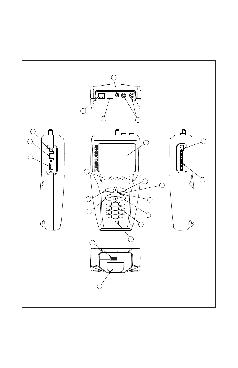
Figure 8. Main Unit Features
15
Page 17
Test-Um NT955 Series
M
E
N
U
A
C
C
P
T
Q
U
I
T
T
E
S
T
SEL
6
MNO
JKL
5
4
GHI
*
7
PRS
0
#
9
TUV
8
QZ
WXY
1 3
ABC
2
DEF
@
ValidatorTM About Your Validator-NTValidatorTM About Your Validator-NT
.
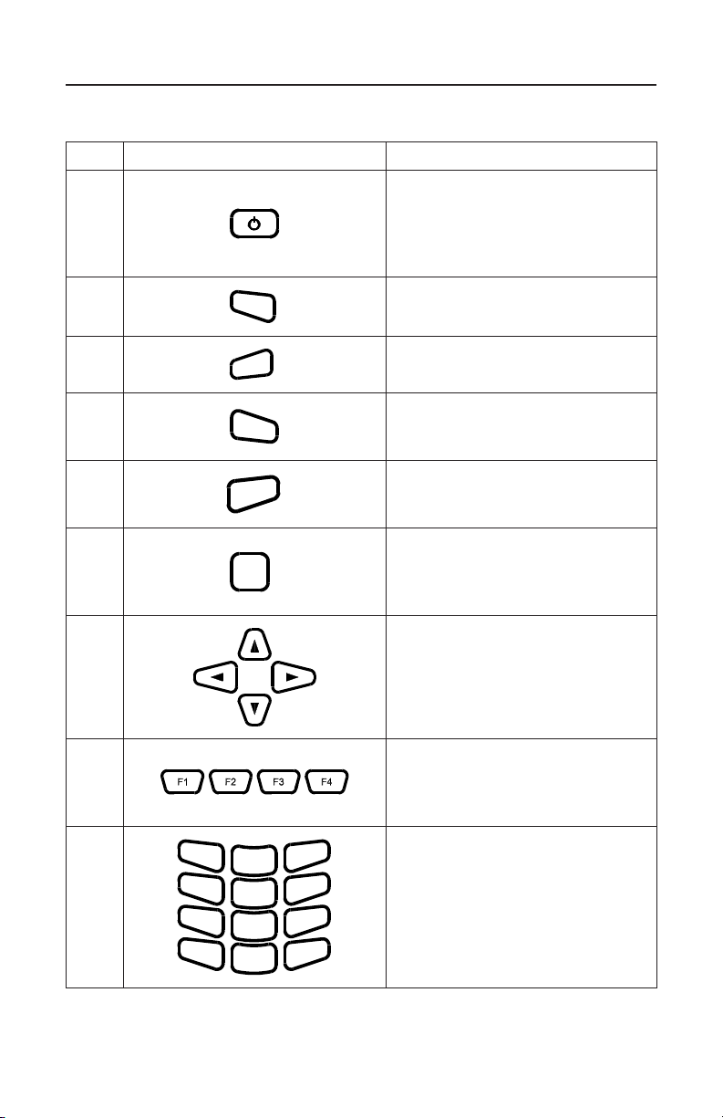
Table 1. Main Unit Features
Item Feature Description
Power Key is pushed to power unit
on/off. When unit is on a short tap
1
changes the backlight from dim to
bright. Holding key down for over a
second turns the unit off.
2
3
Menu Key opens a shortcut
window of simple functions.
Accept Key accepts the current
selection or edited eld.
Quit Key exits the current
4
selections or moves backup in the
menu sequence.
Test Key runs the automatic test
5
sequence for the highlighted
cable.
Select Key enables editing of
6
currently highlighted eld or
activates the next level into the
menu navigation sequence.
Arrow Keys are used for
navigation of the active-selected
7
eld on the current menu.
Context Sensitive function keys
8
enable the soft keys, which
appear on the bottom of the LCD
screen.
Alphanumeric keypad used
to enter data. Pressing the 1
key multiple times displays the
9
following special characters: @
( ) - . , and space. The (*) key is
also a shortcut for the (.) period
punctuation mark.
16
Page 18

Test-Um NT955 Series
ValidatorTM About Your Validator-NTValidatorTM About Your Validator-NT
Table 2. Main Unit Features (Cont.)
Item Feature Description
10 Display 4 inch LCD color screen.
11 Data Jack
12
13
14 Banana Jacks Connection for 2-wire testing
15
16 USB Port
17 DC Power Supply External power supply
18
19 Card Ejector
20 Battery
21 Battery Lock Sliding lever to secure battery
Telephone Jack RJ11, 6 Wire Telco interface,
Coaxial Cable Connector “F” Connector Coaxial Cable
Serial Port
Compact Flash Card
RJ45, 8 wire data interface,
T568A/B pairing.
USOC pairing.
interface
Connection for serial port printer
(Currently inactive)
When computer is sensed
connected to USB port, NT955
powers down and enters USB
mode.
Standard data grade compact
ash card, 32 Megabytes minimum
capacity. Only remove when unit
is off.
Folding ejector button. Fold over to
prevent accidental ejection of the
compact ash card.
Li-ion rechargeable battery
(NT93)
17
Page 19
Test-Um NT955 Series
1
2
4
3
9
11
6
5
8
7
10
VALIDATOR
REMOTE
76~10076~100
50~7550~75
25~4925~49
5~245~24
LOW
BATTERY
STATE
CHARGE
LINK
MADE IN USA
TMTM
Remote Unit Features
ValidatorTM About Your Validator-NTValidatorTM About Your Validator-NT
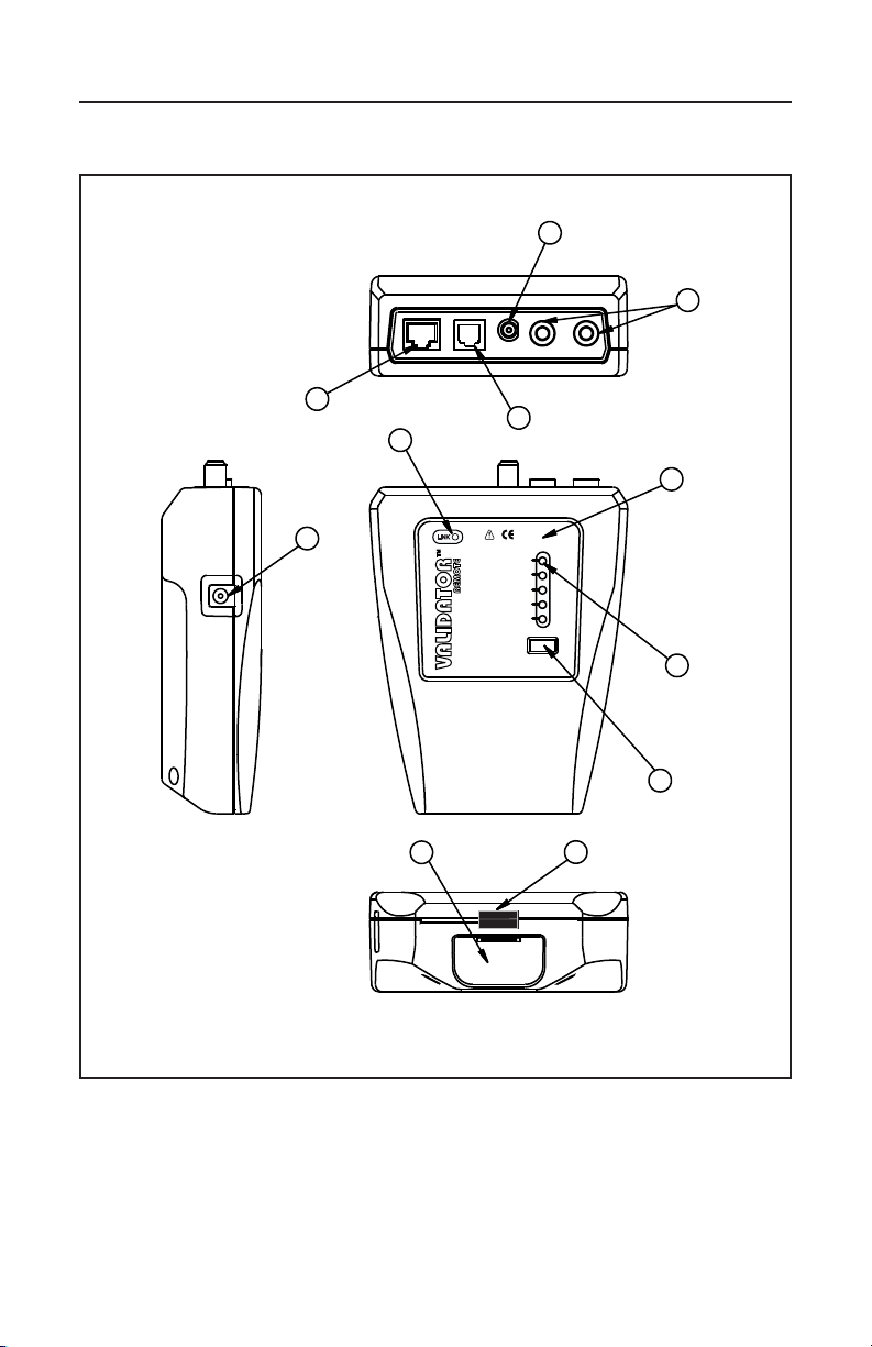
Figure 9. Remote Unit Features
18
Page 20

Test-Um NT955 Series
Table 3. Remote Unit Features
Item Feature Description
ValidatorTM About Your Validator-NTValidatorTM About Your Validator-NT
1 Link LED
2 Charge LED
3 Battery state
4
5 Data Jack
6 Telephone Jack
7
8 Banana Jacks Connection for 2-wire testing
9 DC Power Supply External power supply
10 Battery Li-ion rechargeable battery (NT93)
11 Battery Lock Sliding lever to secure battery
Battery State
Indicator
Coax Cable
Connectors
Turns on when a link is established with
another network device.
Battery is charging when LED light is
blinking.
When selected the battery life capacity is
shown.
Battery life capacity is
76-100 LED
50-75 LED
25-49 LED
5-24 LED
LOW
RJ45, 8 wire data interface, T568A/B
pairing.
RJ11, 6 Wire Telco interface, USOC
pairing.
“F” Connector Coaxial Cable interface
between 76% to 100%,
fully charged
Battery life capacity is
between 50% to 75%
Battery life capacity is
between 25% to 49%
Battery life capacity is
between 5% to 24%
Battery life capacity is
low, and does need to
be recharged.
19
Page 21
Test-Um NT955 Series
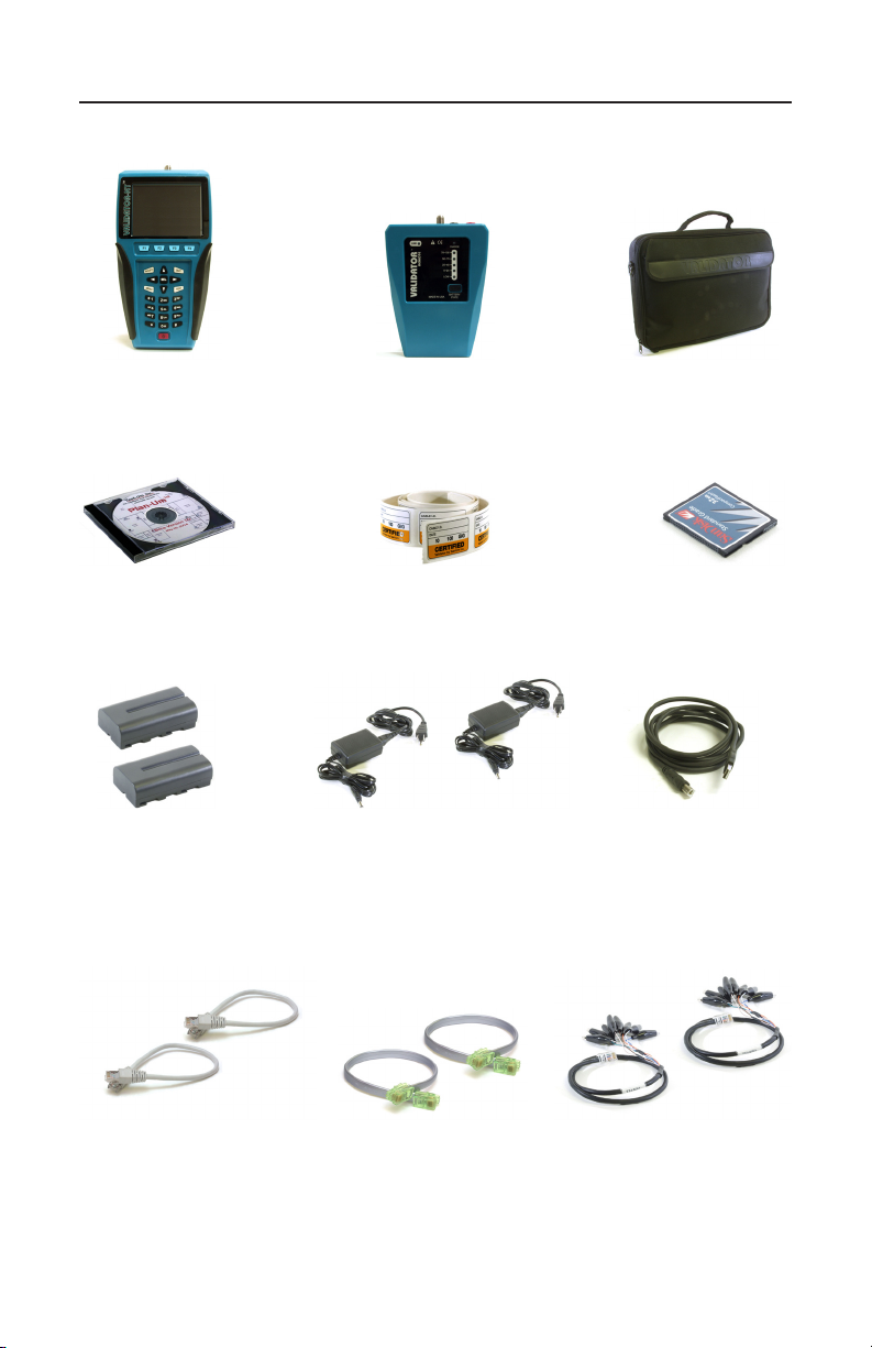
Standard Accessories
NT955
NT955
Validator-NT™
Validator-NT™
NT940
NT940
Plan-Um™
Plan-Um™
Software
Software
ValidatorTM About Your Validator-NTValidatorTM About Your Validator-NT
NT928
NT928
Validator-NT™
Validator-NT™
Remote
Remote
NT95
NT95
Cable Labels
Cable Labels
NT930
NT930
Validator-NT™
Validator-NT™
Carrying Case
Carrying Case
Compact
Compact
Flash Card
Flash Card
(2) NT93
(2) NT93
Lithium-ion
Lithium-ion
Rechargeable
Rechargeable
Batteries
Batteries
(2) TP55
(2) TP55
12” Cable
12” Cable
Assemblies,
Assemblies,
Shielded RJ45
Shielded RJ45
Connectors
Connectors
(2) NT92
(2) NT92
AC Adapter,
AC Adapter,
Charger Units
Charger Units
(2) TP20
(2) TP20
7.5” Cable Assemblies,
7.5” Cable Assemblies,
No Fault
No Fault
RJ12 Connectors for RJ11
RJ12 Connectors for RJ11
or RJ45
or RJ45
20
(2) NT94
(2) NT94
72” Cable
72” Cable
Assembly, USB
Assembly, USB
(2) TP68
(2) TP68
24” Cable
24” Cable
Assemblies,
Assemblies,
RJ45 with 8
RJ45 with 8
Alligator Clips
Alligator Clips
Page 22
Test-Um NT955 Series
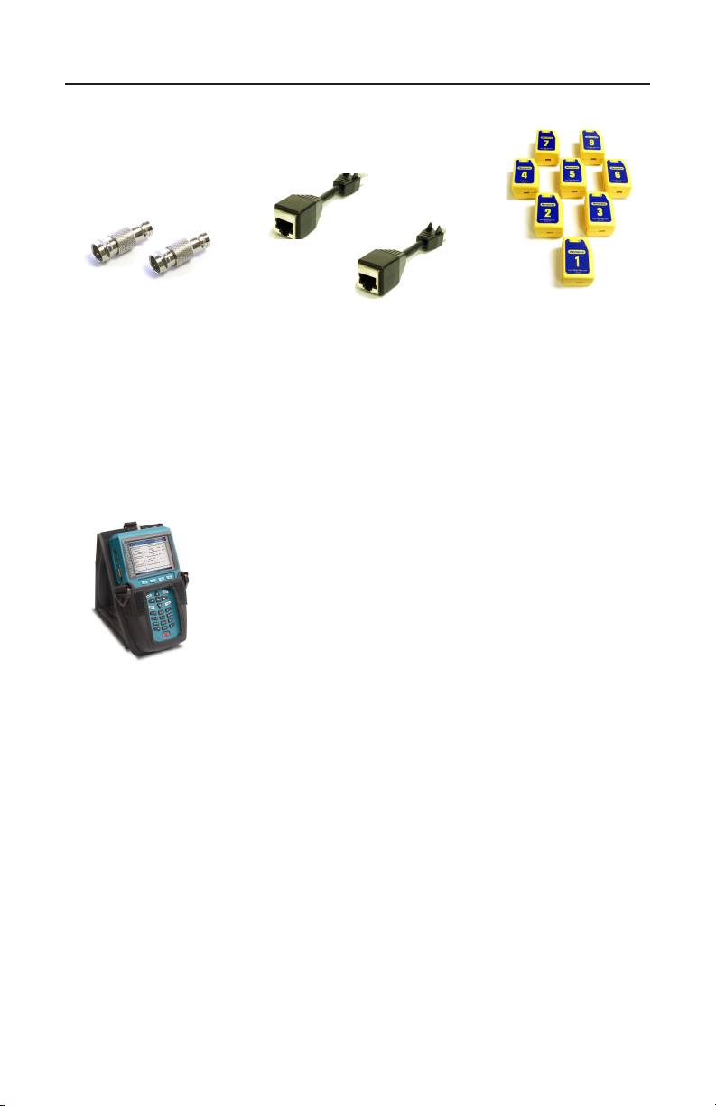
Standard Accessories (Continue)
(2) TP74
(2) TP62
(2) TP62
Adapters, BNC Plug
Adapters, BNC Plug
to F Jack
to F Jack
Extending Modular Plug
Extending Modular Plug
(2) TP74
Sacricial Cables for
Sacricial Cables for
Optional Accessories
ValidatorTM About Your Validator-NTValidatorTM About Your Validator-NT
TP610
TP610
Set of 8 Wiremap
Set of 8 Wiremap
Remotes
Remotes
NT935
NT935
Validator Main Unit
Validator Main Unit
Carrying Case
Carrying Case
21
Page 23
Test-Um NT955 Series
6
MNO
JKL
5
4
GHI
*
7
PRS
0
#
9
TUV
8
QZ
WXY
M
E
N
U
1
A
C
C
P
T
T
E
S
T
3
ABC
2
DEF
SEL
Q
U
I
T
VALIDATOR-NT
TM
OPEN RENAME
COPY
DEL JOB
Job Manager
Untitled1.job
Test-Um Inc.
validator
File Name Modified File Size
Test-um.job
Technicolor.job
Untitled1.job
10.21 Wed 2005 Oct 06
9.51 Fri 2005 Oct 08
10.00 Mon 2005 Oct 11
25.1 K
11.7 K
5.7 K
Magicworld.job
13.17 Tue 2005 Oct 05
13 K
100%
2005 Aug 25
10:53:01
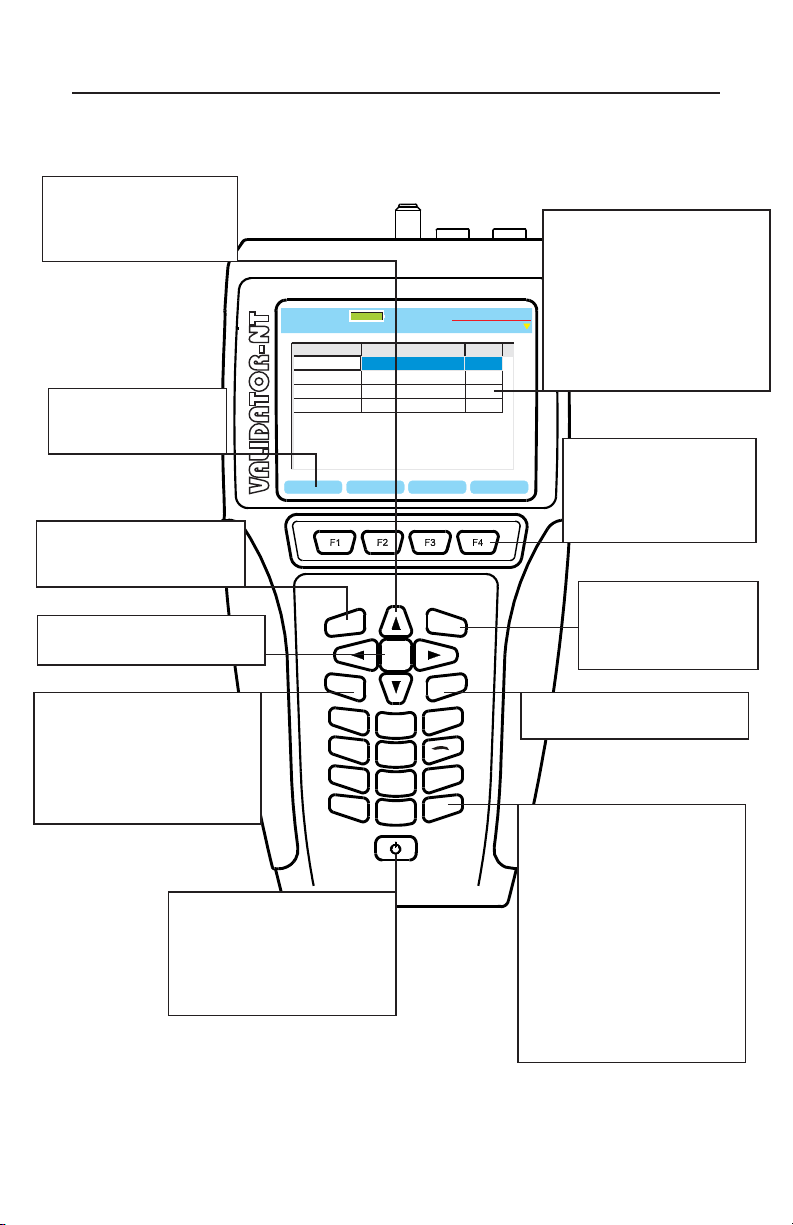
Menu Options & Navigation
Arrow Keys – are used
to navigate up, down,
right, or left between
cells, words or spaces.
Soft Keys – Denes
functions specic to
the current screen.
*Accept Key – used to
exit a cell and accept any
changes that were made.
*Select Key – is used to
enter a menu or cell.
*Menu Key – prompts a
menu that displays options
for going back to the start
screen, saving your job,
printing or shutting down the
Compact Flash Card.
*Power Button – is used to
power the unit on/off. When
the unit is on, a short tap
dims the backlight. Holding
key down for over a second
turns the unit off.
ValidatorTM About Your Validator-NTValidatorTM About Your Validator-NT
Cells – are boxes for
inputting data. To enter a cell,
press the Select Key. Use
the Alphanumeric Keys and
the Arrow Keys to enter data
and create spaces. Press the
Accept Key to exit a cell and
automatically increment to
the next cell.
Function Keys Execute the soft key
functions displayed
above them on the
screen.
*Quit Key – is used
to navigate backwards
one step or exit a cell
without changing it.
*Test Key – is pressed to
initiate a test procedure.
Alphanumeric keypad – is
used to enter data. Multiple
presses of a key advance the
letters and numbers of each
key. The cursor will increment
to the next space when a
different key is pressed.
When the subsequent letter
is on the same key, advance
the cursor to the next space
using the right arrow key
before pressing the key
again.
Figure 10. Keypad Navigation
22
Page 24

Test-Um NT955 Series
ValidatorTM Battery and Power ManagementValidatorTM Battery and Power Management
Battery and Power Management
The lithium-ion rechargeable batteries (NT93) included with the ValidatorNT main unit and remote are recharged any time the Validator-NT or
remote are connected to the AC adapters included in the Validator-NT
kit. Use of other adapters, particularly car adapters, should always be
avoided.
The batteries continue to charge during operation. The batteries included
in the kit are designed to work with the Validator-NT battery information
system. They have the ability to store usage information that can be
used to monitor the loss of capacity in the battery over time. Using other
batteries of similar style will result in not knowing the battery condition or
state of charge.
Each unit can run on battery power for approximately 8 hours. Since the
remote uses considerably less power than the Validator-NT main unit, a
full days use can be assured by swapping the batteries between the two
in the middle of the day.
A full recharge cycle takes approximately 2 ½ half hours.
The lithium-ion batteries for Validator-NT can be used and stored in
locations that do not exceed 122 degrees Fahrenheit (50 degrees
Celsius) or 32 degrees Fahrenheit (0 degrees Celsius) limits. If the
Validator-NT senses an out of range condition while charging, it displays
Hot or Cold below the battery symbol and suspends charging. The
remote ashes the charging light rapidly and suspends charging for as
long as the temperature is out of range.
Note: Do not discard lithium-ion batteries in an area where they can
be burned or in regular trash. Li-Ion batteries can explode if exposed
to open ame and create hazardous waste. Dispose in a proper
environmentally safe fashion.
WEEE Compliant: Prior to disposal of this product, please
contact Test-Um Inc for proper disposal options.
23
Page 25

Test-Um NT955 Series
Validator-NT Main Unit
When powered on, the Validator-NT reports the charging status at the top
of the screen under the battery icon. A green full battery icon indicates
the battery is fully charged. As the battery discharges, the percentage of
remaining charge is displayed in 10% steps. The battery icon changes
from green to amber when the battery reaches approximately 30% of its
charge capacity.
When the battery is Low, the battery icon will change to red and
begin to ash. An audible warning tone will sound when the battery
reaches approximately 10% of its charge capacity to notify the user
that in approximately three minutes, the Validator-NT will power down
automatically and save the current job.
Note: The battery must be fully charged the rst time it is used to report charging status. After one full charge, the batteries in the main unit
and the remote unit are interchangeable.
If the battery is replaced, it is necessary to start a new charge cycle by
either disconnecting the AC adapter momentarily or pressing the Reset
Charge (RST CHRG) soft key (F1) on the Properties/Battery Info screen.
In addition to the charging status, additional information that is useful to
monitor the loss of capacity in the battery over time is displayed on the
Battery Properties screen.
ValidatorTM Battery and Power ManagementValidatorTM Battery and Power Management
Charging will continue when the Validator-NT is powered off but there is
no visual indication. The Validator-NT has various timeout conditions to
conserve battery life. The specic timeout values are adjustable in the
Setup, Shutdown Timeouts screen.
24
Page 26

Test-Um NT955 Series
Validator-NT Remote Unit
The Remote unit has a battery charge indicator light that is on solid
during rapid charge, blinks slowly while topping off, or is off when
charging is completed. The 76-100% light will be on to indicate a fully
charged battery. The remote unit displays the percentage of charge
remaining in 25% increments. If no lights are on while powered by an AC
adapter, the battery is not inserted.
If the battery is replaced by another while topping off, it is necessary
to press the Battery State button to initiate a new charge cycle. When
operating from battery, a state of charge light is on whenever the remote
is auto-powered on by the Validator-NT or the Battery State button is
pressed.
Although the display capability is limited on the remote, you can view the
detailed charging information on the remote battery by inserting it in the
main unit.
ValidatorTM Battery and Power ManagementValidatorTM Battery and Power Management
25
Page 27
Test-Um NT955 Series
Battery Lock Feature
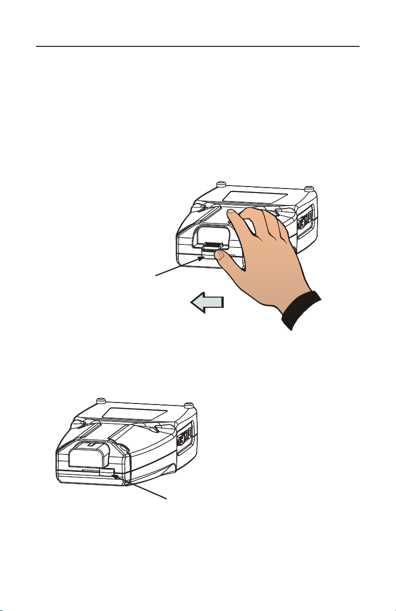
A Battery Lock feature on the main and remote Validator-NT units is
designed to prevent accidental ejection of the battery.
Apply pressure with your thumb to slide the Battery Lock lever across the
channel to secure the battery in the locked position (see Figure 11) and
in the opposite direction to unlock the Battery Release button (see Figure
12). Press the Battery Release button to eject the battery.
Locking PositionLocking Position
ValidatorTM Battery and Power ManagementValidatorTM Battery and Power Management
Figure 11. Battery Locking PositionFigure 11. Battery Locking Position
Open Position Open Position
Figure 12. Battery Lock Open Figure 12. Battery Lock Open
26
Page 28

Test-Um NT955 Series
ValidatorTM OperationsValidatorTM Operations
Operations
The Validator-NT main unit is powered on by pressing the red power
button. When powering on, the unit will display a series of start up
screens until the Start screen is reached, which contains the main menu.
At the top of every screen the following information appears - The name
of the screen being displayed “Start, Auto Test” etc., the current job
name, the battery condition and the date/time from the internal clock.
The Validator-NT always has a le open, which is the current le name
that appears at the top of the screen, so that data can be saved in
the event of auto-power down. The last job opened will remain as the
current job until changed even through on and off cycles.
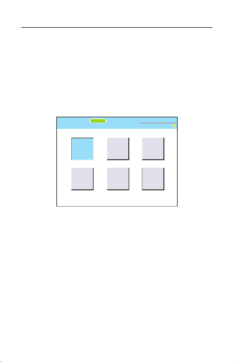
The Start screen has ve buttons: Auto Test, Manual Tests, Network
Tests, Job Manager, Setup and Properties. You can navigate between
these buttons with the arrow keys that move from left to right on each
row.
Auto Test
Selecting this button takes you to a menu of ve functions used to work
with existing jobs or create new jobs and test cables. Test Results are
automatically saved and can be downloaded to Plan-Um to document
and archive the job.
Cable Test Schedule: Tests cables from a predened job le or deneas-you-go Cable Schedule using Pass/Fail criteria.
Site Information and Contractor Information: View, edit or create this
job information.
Custom Cable Denitions: View existing cable denitions and create
or edit custom cables.
Job Utilities: File utilities used to create or manipulate job les.
Manual Tests
Select this button to test data, phone, or 2 wire cables without dening
the job, cable name or type. The specied test is run and the raw results
displayed without pass or fail criteria being applied. Manual tests cannot
be saved as Auto Tests can.
27
Page 29

Test-Um NT955 Series
Network Tests
Selecting this button takes you to a menu of three manual tests that
report the condition of the cable and verify connectivity to network
devices. They are Port Discovery, Ping Test, and Hub Flash. Test
Results cannot be saved.
Port Discovery: Identies an Ethernet connection and reports pertinent
information including speed of the link, type of link (MDI, MDI-X or Auto
MDI/MDI-X), Signal to Noise Ratio and Skew (if over 1000 Megabit). Also
Identies telephone connections.
Ping Test: Simultaneously pings up to seven different IP addresses and
can be run in DHCP or manual addressing modes.
Hub Flash: Sends an intermittent link signal to ash the link status light
on Ethernet equipment.
Job Manager
The Job Manager displays a list of jobs that have been uploaded from
the Plan-Um software or have been created in the Validator-NT and are
on the CF card. By highlighting a job name and pressing the Open (F1)
soft key you can select an existing job to test or edit the job information
using the Auto Test menu functions.
ValidatorTM OperationsValidatorTM Operations
Setup
This key takes you to internal adjustment functions of Validator-NT such
as Display Units, Display Contrast, internal time settings, Shutdown
Timeouts etc. Normally these can be set once and left alone unless
some specic change is desired. Each function has drop down dialog
boxes for changes, if necessary.
Properties
This screen displays internal information on Validator-NT such as Battery
life, Compact Flash usage, revision levels, support phone numbers and
web site support information etc.
28
Page 30
Test-Um NT955 Series
Printer
Settings
Locali-
zation
Shutdown
Timeouts
Display
Contrast
Setup
Untitled1.job
Calibrate
Real
Time
Clock
Test-Um Inc.
validator
100%
2005 Aug 25
10:53:01
ValidatorTM Setting Up the Test ToolValidatorTM Setting Up the Test Tool
1. Setting Up the Test Tool
The Setup menu allows the user to adjust internal functions such as
Display Contrast, the internal time clock, English or Metric units, the
displayed language, and Shutdown Timeouts. Most of these functions
can be set once and left alone unless a specic change is desired. In
addition, although currently not functional, future upgrades may permit
the user to print Test Results directly from the Validator-NT to a serial
port printer.
Figure 1.1 Setup Screen
29
Page 31

Test-Um NT955 Series
+
-
Test-Um Inc.
validator
100%
2005 Aug 25
10:53:01
Set LCD Contrast
Untitled1.job
ValidatorTM Setting Up the Test ToolValidatorTM Setting Up the Test Tool
1.1. Display Contrast
The Validator-NT main unit allows contrast settings for different
environments. Use the + (F1) soft key to increase the contrast for a dark
environment or – (F2) soft key to decrease the LCD contrast in a bright
environment (see Figure 1.2).
Figure 1.2 Display Contrast Settings
30
Page 32
Test-Um NT955 Series
Save
115200
Bit Rate:
Printer
Untitled1.job
100%
Test-Um Inc.
validator
2005 Aug 25
10:53:01
ValidatorTM Setting Up the Test ToolValidatorTM Setting Up the Test Tool
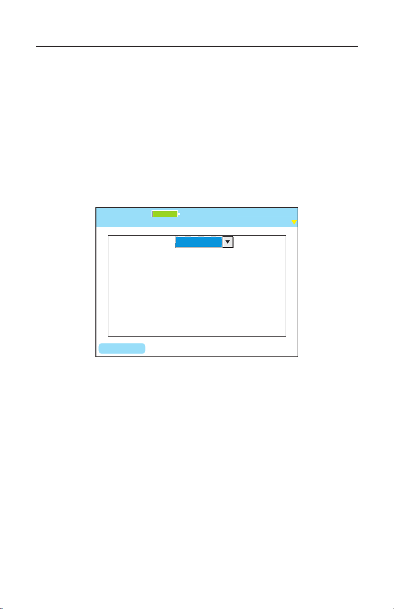
1.2. Printer Settings
Select Printer Settings (see Figure 1.3). A pull down menu appears
which displays common Bit Rates for printers. The Bit Rate you select
must match the Serial Port Printer properties of the printer you use.
Press Save (F1) to set and exit Printer Settings.
Use the serial port on the left side of the Validator-NT to connect to the
printer. A Cable Assembly is not provided.
Figure 1.3 Bit Rate Settings for Printers
31
Page 33
Test-Um NT955 Series
System Shutdown (min):
Shutdown Screen
Untitled1.job
15
Backlight Shutdown (min):
30
15
Tone Generator Timeout (min):
Set
Test-Um Inc.
validator
Shutdown
Untitled1.job
100%
Test-Um Inc.
validator
2005 Aug 25
10:53:01
ValidatorTM Setting Up the Test ToolValidatorTM Setting Up the Test Tool
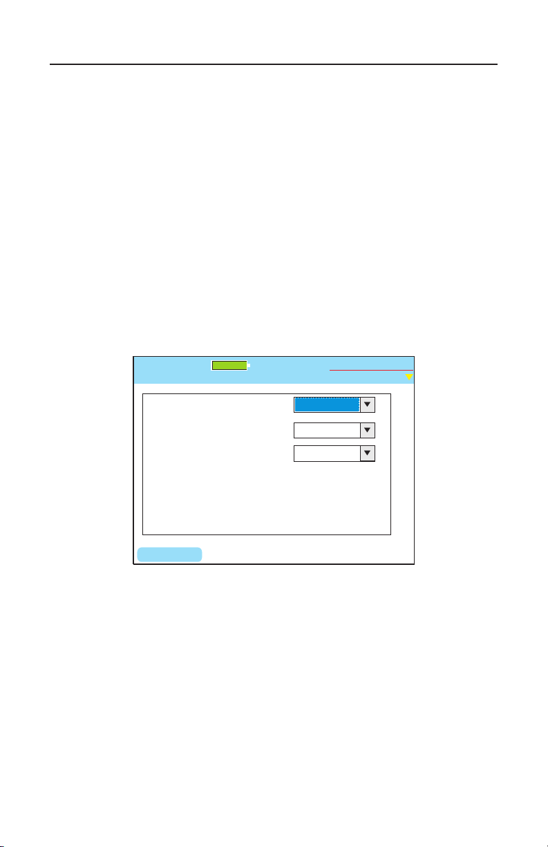
1.3. Shutdown Timeouts
A Power Save mode is installed in Validator-NT to conserve battery life
(see Figure 1.4). When the pre-set time limit is reached without any key
input the main unit screen will begin to blink. Pressing any key will bring
back the full screen and reset the timer.
Select preferences for the timeframes in minutes that you wish the
Backlight, the Validator-NT Operating System, and the Tone Generator
to automatically shutdown and timeout in order to preserve battery
life. Click the down arrow on each drop down dialog box and select the
number of minutes desired before each function turns off. Press Accept,
then press Set (F1) to initiate your selections and return to the Setup
screen.
Figure 1.4 Shutdown Settings
32
Page 34
Test-Um NT955 Series
Set
Month:
Real Time Clock
Untitled1.job
2005
Year:
August
10
25
Day:
Hour:
53
Minute:
Test-Um Inc.
validator
100%
2005 Aug 25
10:53:01
ValidatorTM Setting Up the Test ToolValidatorTM Setting Up the Test Tool
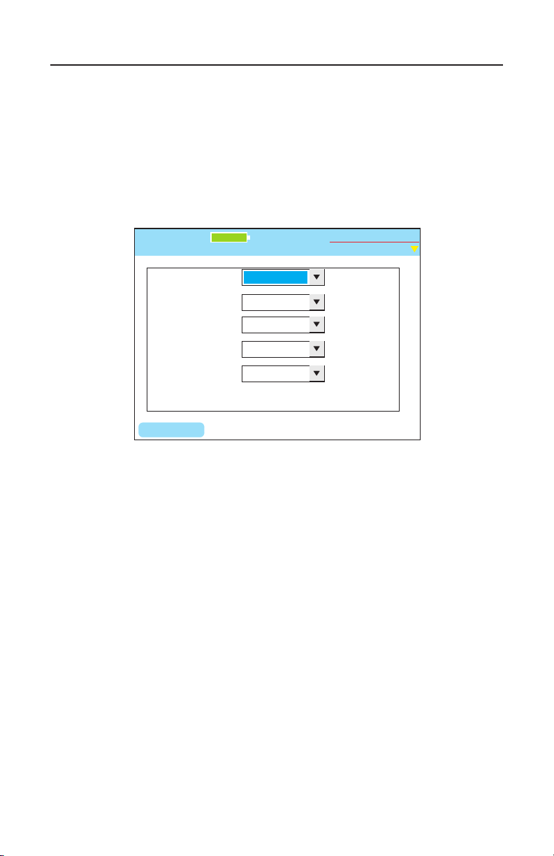
1.4. Set the Clock using the Real Time Clock Screen
Using the drop down dialog boxes, select the current year, month, day,
hour, and minute (see Figure 1.5). Press Accept to select your choice
and move to the next eld. Press Set (F1) to conrm your choices and
return to the Setup Screen.
Figure 1.5 Real Time Clock Settings
33
Page 35
Test-Um NT955 Series
OK
Units
Untitled1.job
Test-Um Inc.
validator
Current Unit:
English
100%
2005 Aug 25
10:53:01
Current Language:
English
ValidatorTM Setting Up the Test ToolValidatorTM Setting Up the Test Tool
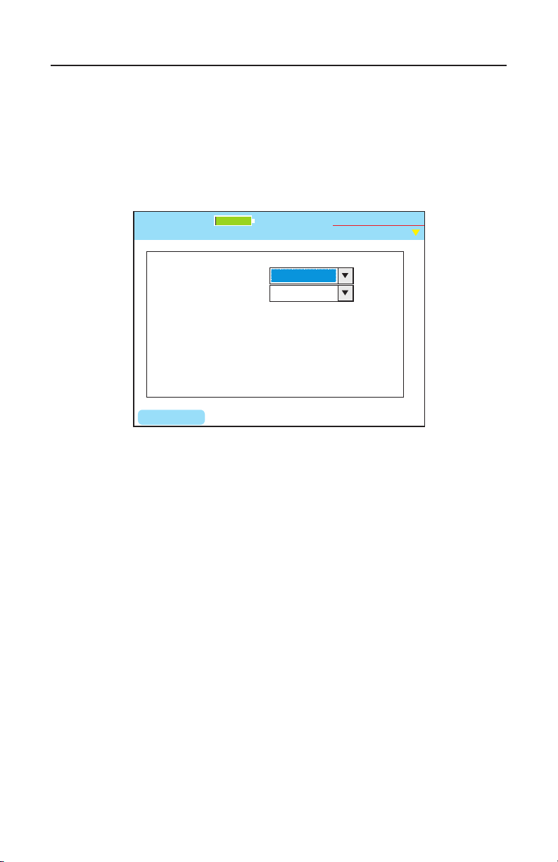
1.5. Localization
Using the drop down dialog box, select Metric or English units to report
length measurements (see Figure 1.6). Press Accept. Press OK to
conrm your choice and return to the Setup screen.
Figure 1.6 Localization Settings
34
Page 36
Test-Um NT955 Series
Calibrate
Untitled1.job
Continue
To calibrate the unit make sure there are no
cables plugged into the unit. (Unless a patch
cord is being used)
Test-Um Inc.
validator
100%
2005 Aug 25
10:53:01
ValidatorTM Setting Up the Test ToolValidatorTM Setting Up the Test Tool
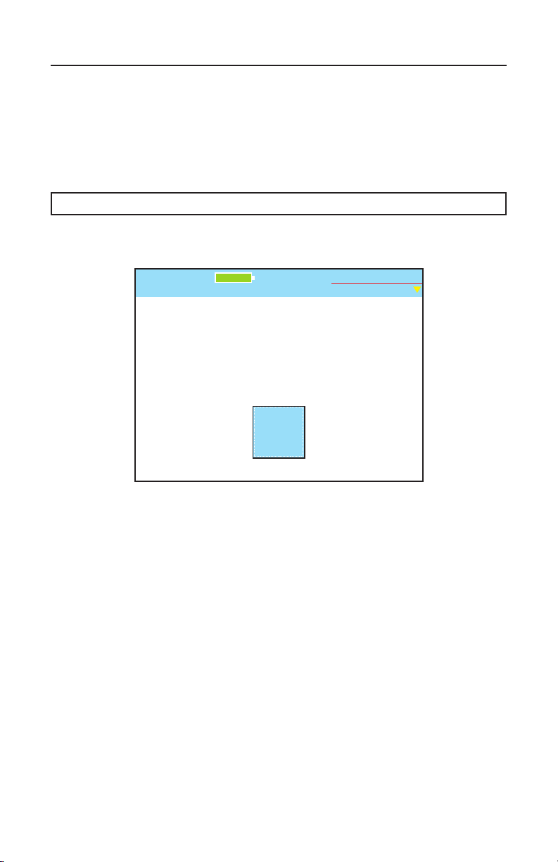
1.6. Calibrate
The calibration procedure is performed to set a reference point for cable
length to 0 feet/meters. Once calibration is performed, the test unit
retains the information. The Validator-NT does not require any other
calibration. (Figure 1.7)
Note: Please disconnect all Patch Cables
Figure 1.7 Calibrating The Unit
35
Page 37
Test-Um NT955 Series
Support
Info
Product
Version
CF Card
Usage
Battery
Info
Properties
Untitled1.job
Test-Um Inc.
validator
100%
2005 Aug 25
10:53:01
ValidatorTM PropertiesValidatorTM Properties
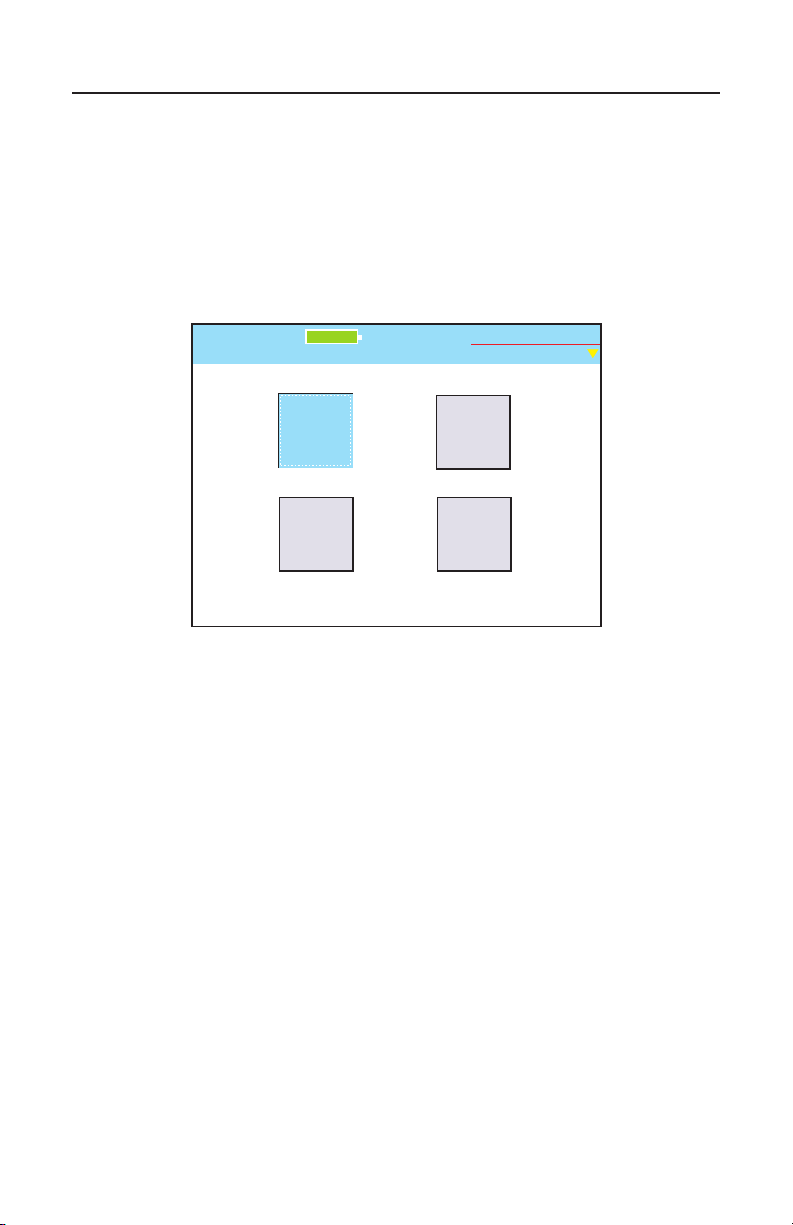
2. Validator-NT Properties
The Properties menu displays buttons that contain internal information on
the state of charge associated with the battery, product revision levels,
available free space on the Compact Flash card, and Test-Um support
information. (Figure 2.1)
Figure 2.1 Properties Menu
36
Page 38

Test-Um NT955 Series
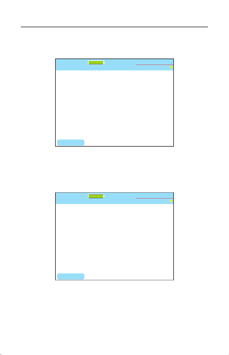
2.1. Battery Info
This screen indicates whether the unit is operating on Battery Power or
External Power and displays information that allows the user to monitor
the remaining charge status and aging of the battery.
(Figure 2.2 & Figure 2.3)
Charge Remaining: Displays the percentage of charge
remaining in percentages ranging from 0% to 100%. As the
battery discharges, the percentage of remaining charge is
reported in 10% steps.
Status: Reports the status of the charge cycle as Charging,
Normal (temperature in range), Charge Cycle Complete,
Automatic Shutdown Pending, Temperature Out of Range (too
high or too low to charge), Cannot Read Battery Status, or No
Battery.
Serial Number: Allows the user to identify a specic battery
Charge Cycles: Reports the number of times the battery
charger completes the charge cycle.
ValidatorTM PropertiesValidatorTM Properties
Remaining Maximum Capacity: An estimate of the ability of
the battery to store the charge.
Total Charge Accumulated: Tracks the amount of charge put
into the battery.
The Battery Info screen also includes a Reset Charge (RST CHRG) F1
soft key. The purpose of this function is to reset the charge cycle when
you change out the battery. You can also start a new charge cycle by
disconnecting the AC adapter momentarily.
The battery from the remote can be placed into the main unit and its
properties can be viewed.
Note: For additional power and battery information see the Battery
and Power Management section of this guide.
37
Page 39
Test-Um NT955 Series
Battery Properties
Untitled1.job
RST CHRG
Test-Um Inc.
validator
100%
2005 Aug 25
10:53:01
BATTERY POWER
Charge Remaining - 100%
Serial Number - 3462150
Charge cycles --1
Remaining Maximum Capacity - 100%
Total Charge Accumulated - 2
Status - Normal
Battery Properties
Untitled1.job
RST CHRG
Test-Um Inc.
validator
100%
2005 Aug 25
10:53:01
EXTERNAL POWER
Charge Completion - 50%
Serial Number - 3462150
Charge cycles --1
Remaining Maximum Capacity - 100%
Total Charge Accumulated - 2
Status - Charging
Figure 2.2 Unit Operating on Battery Power
ValidatorTM PropertiesValidatorTM Properties
Figure 2.3 Unit Operating on External Power
38
Page 40
Test-Um NT955 Series
Serial Number
30745
VAL_Board
01.01
VAL_Boot
VAL_Batt
01.05
02.03
VAL_JFFS2
VAL_PIC
VAL_Root
VAL_valapp
02.03
02.11
02.01
02.03
Revisions
Untitled1.job
Component Revision
Test-Um Inc.
validator
100%
2005 Aug 25
10:53:01
ValidatorTM PropertiesValidatorTM Properties
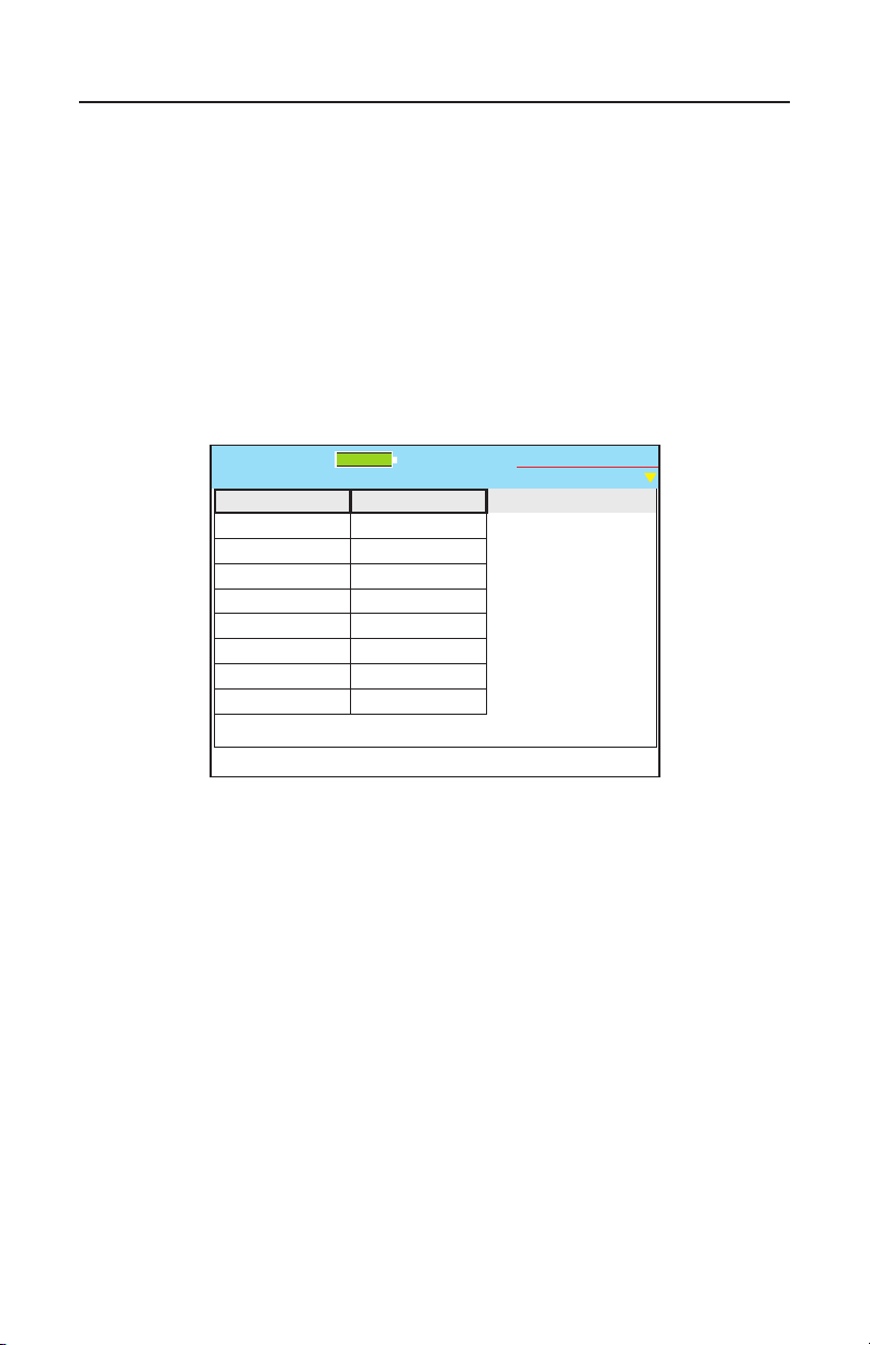
2.2. Product Version
This screen displays the product’s electronic serial number plus the
revision levels of the hardware, rmware and software in the ValidatorNT (See Figure 2.4).
Should you require technical assistance you may be asked to refer to this
screen to conrm current product revision information. This screen will
also be important in managing future product upgrades and updates.
Figure 2.4 Unit Revision Properties
39
Page 41
Test-Um NT955 Series
CF Properties
Untitled1.job
70% available
42973 KB free 62315 KB total
Test-Um Inc.
validator
100%
2005 Aug 25
10:53:01
ValidatorTM PropertiesValidatorTM Properties
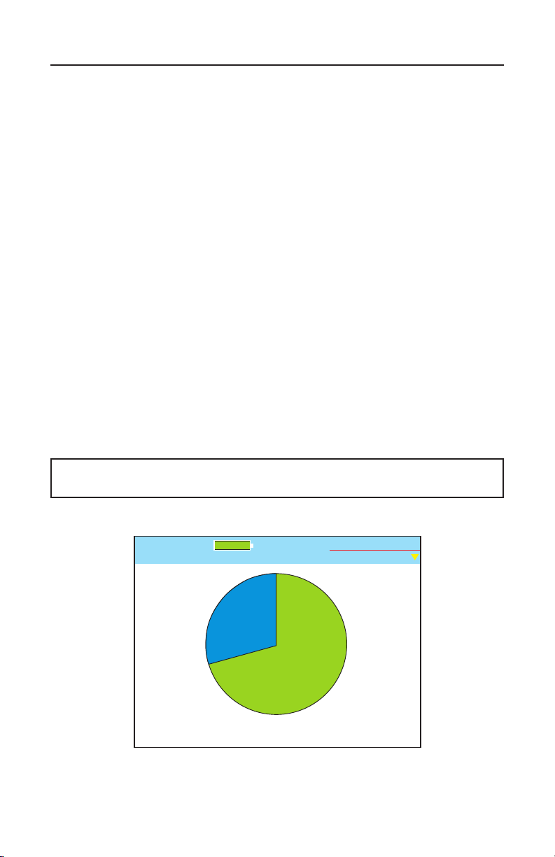
2.3. Compact Flash Card Usage
The Validator-NT kit includes a high quality mass storage compact ash
card. Approximately 6000 cable tests can be stored per 32 Megabytes
of card space. Press Select to view a pie chart that displays free card
space with numeric values for percentage and kilobytes available
(See Figure 2.5).
Validator-NT requires compact ash cards that are intended for mass
storage use and support both true IDE and PCMCIA interface modes of
operation.
To remove the compact ash card while the unit is powered on, press
Menu then CF Shutdown. The triangle at the top right corner of the
screen changes from yellow to green. When it turns green, you can
remove the ash card by gently pulling up and unlocking the ejector
button and pushing it to eject the card.
To reinsert the card, place the contact side of the card in the slot and
press gently to lock it in place. When the card is seated, gently pull up
and press the ejector button into the locked position. A card must be in
place in order to use the Validator-NT.
Warning! Removing the compact ash card with the power on without
using the CF eject function may cause data loss.
Figure 2.5 Compact Flash Card Properties
40
Page 42

Test-Um NT955 Series
Support
Untitled1.job
Support Email:
Validator Support Information:
Web Page:
Phone: (805)383-1500
www.test-um.com
Manage Firmware
Test-Um Inc.
validator
100%
2005 Aug 25
10:53:01
ValidatorTM PropertiesValidatorTM Properties
2.4. Support Info
The Support Screen displays Technical Support contact information,
including our web site, telephone number, and e-mail address. The NT955
Technical Reference Manual is available at www.test-um.com.
In addition a blue box titled Manage Firmware displays which you will be
able to select in the future to download product revisions from our web
site. Specic update procedures will be included with the update le.
1. With the Validator-NT powered off, connect the USB cable to your
Validator and to the USB port on your PC.
2. Power On the Validator-NT and a message appears “USB-File
I/O Mode.” From the Test-Um Inc. web site (www.test-um.com),
select the downloads button and login. Follow the instructions to
Download Firmware directly to the compact ash card.
3. Carefully remove the USB Cable after the le transfer has been
completed following the instructions in Uploading/Downloading
jobs.
4. Select Properties from the Start screen, then Support Info.
(Figure 2.6)
5. Manage Firmware is already highlighted and can be accessed
by pressing Select. A progress indicator will appear while the
rmware les load.
Figure 2.6 Support Information
41
Page 43
Test-Um NT955 Series
INSTALL
Firmware Package
VAL-full-02.03.TUI
Manage Firmware
Untitled1.job
Test-Um Inc.
validator
100%
2005 Aug 25
10:53:01
ValidatorTM PropertiesValidatorTM Properties
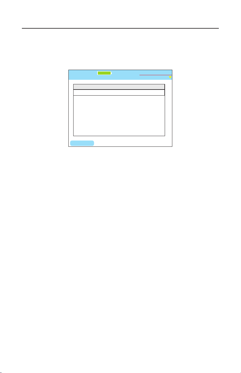
6. Select the rmware le from the Firmware Package list. Press
the Install soft key (F1) to install the rmware. (Figure 2.7)
Figure 2.7 Firmware Manager
7. The Firmware Revisions screen will show the new revision in
the Now column. It also shows the minimum revision level
necessary for compatibility with the new component.
8. A Green check in the component column indicates the existing
component is compatible with the new. A Red check signies
it is not. If this occurs, call Test-Um support. Do not attempt to
operate the Validator-NT with incompatible les.
9. If all components have a Green check press Continue (F1) to
begin the update process. Do not interrupt the update process
that can take several minutes.
10. The Validator-NT automatically reboots when the update is
complete.
11. From the Properties screen, select Product version to verify all
updates installed correctly.
42
Page 44

Test-Um NT955 Series
ValidatorTM Managing Job FilesValidatorTM Managing Job Files
3. Managing Job Files
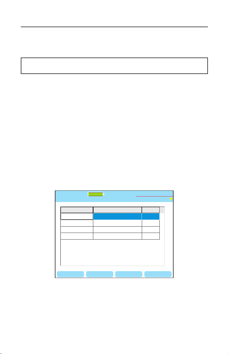
The Job Manager screen is used to view a list of all job les stored on
the compact ash (CF) card. Use the up and down arrows to highlight
the job entry of interest. The soft keys are labeled with the functions
that can be performed on the currently highlighted job: Open, Copy,
Rename, or Delete. (Figure 3.1)
When the Validator is powered on, the current job (the last job opened in
the Validator) displays in the upper left corner of the screen. This makes
it easy to proceed directly to the Auto Test mode for that job. When you
upload a new job, you must navigate to the Job Manager to view the list
of all jobs and select the job you wish to open. If a job has never been
created or opened, the current job will be “untitled1.job.”
43
Page 45
Test-Um NT955 Series
OPEN RENAME
COPY
DEL JOB
Job Manager
Untitled1.job
Test-Um Inc.
validator
File Name Modified File Size
Test-um.job
Technicolor.job
Untitled1.job
10.21 Wed 2005 Oct 06
9.51 Fri 2005 Oct 08
10.00 Mon 2005 Oct 11
25.1 K
11.7 K
5.7 K
Magicworld.job
13.17 Tue 2005 Oct 05
13 K
100%
2005 Aug 25
10:53:01
ValidatorTM Managing Job FilesValidatorTM Managing Job Files
Press the OPEN (F1) soft key to open the selected job. Opening the job
will switch you to the Auto Test screen where the Cable Test Schedule
displays all of the cable runs associated with the selected job.
Note: If there is unsaved data from the currently selected job, a pop-up
window displays providing the option to save the current job.
The COPY (F2) soft key is used to make an exact copy of the highlighted
job with a different name. This can be useful as a backup or as a starting
point for another job that is similar.
The RENAME (F3) soft key is used to revise the name of the highlighted
job.
The DEL JOB (F4) soft key will permanently remove the job from the CF
card. A pop-up window asks you to conrm your request to delete the
selected job. As a precaution, you cannot delete a job that is currently
open. You must select and open a different job and then scroll to the job
you wish to delete and press DEL JOB.
Figure 3.1 Job Manager
44
Page 46
Test-Um NT955 Series
Export Tut
Open
New
Job Utilities
Untitled1.job
Save As
Save
Test-Um Inc.
validator
100%
2005 Aug 25
10:53:01
ValidatorTM Managing Job FilesValidatorTM Managing Job Files
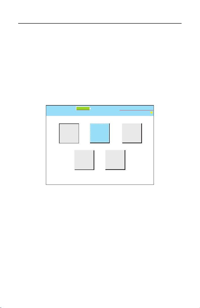
The Job Utilities screen provides the ability to create new jobs and
template (*.Tut) les as well as the Save As function to save the current
job information in memory under a different job name. From the Start
screen, select Auto Test, and use the right arrow key to scroll to Job
Utilities. The Save command on this screen is the same as the save in
the Menu Window, which saves the current RAM memory contents to the
currently loaded job’s le.
In addition, this screen provides a shortcut to the Job Manager. Press
Open to access a list of les stored in the Job Manager. (Figure 3.2)
Figure 3.2 Job Utilities
45
Page 47
Test-Um NT955 Series
Start
Untitled1.job
100%
Test-Um Inc.
validator
2005 Aug 25
10:53:01
Manual
Tests
Network
Tests
Auto
Test
Setup
Properties
Job
Manager
Start
Untitled1.job
100%
Test-Um Inc.
validator
2005 Aug 25
10:53:01
Manual
Tests
Network
Tests
Auto
Test
Setup
Properties
Job
Manager
Current Job
Untitled1.job
Site Info
Contractor
Info
Cable
Test
Schedule
Job Utilities
Custom
Cable
Definitions
Test-Um Inc.
validator
2005 Aug 25
10:53:01
100%
Current Job
Untitled1.job
Site Info
Contractor
Info
Cable
Test
Schedule
Job Utilities
Custom
Cable
Definitions
Test-Um Inc.
validator
2005 Aug 25
10:53:01
100%
Filename:
Template File:
New File
Untitled1.job
Default.tut
DELETE OKBACKSPC
Test-Um Inc.
validator
100%
2005 Aug 25
10:53:01
ExampleFilename:
Template File:
New File
Untitled1.job
Default.tut
DELETE OKBACKSPC
Test-Um Inc.
validator
100%
2005 Aug 25
10:53:01
Example
Current Job
example.job
Site Info
Contractor
Info
Cable
Test
Schedule
Job Utilities
Custom
Cable
Definitions
Test-Um Inc.
validator
2005 Aug 25
10:53:01
100%
Current Job
example.job
Site Info
Contractor
Info
Cable
Test
Schedule
Job Utilities
Custom
Cable
Definitions
Test-Um Inc.
validator
2005 Aug 25
10:53:01
100%
Export Tut
Open
New
Job Utilities
Untitled1.job
Save As
Save
Test-Um Inc.
validator
100%
2005 Aug 25
10:53:01
Export Tut
Open
New
Job Utilities
Untitled1.job
Save As
Save
Test-Um Inc.
validator
100%
2005 Aug 25
10:53:01
ValidatorTM Managing Job FilesValidatorTM Managing Job Files
3.1. Creating A New Job
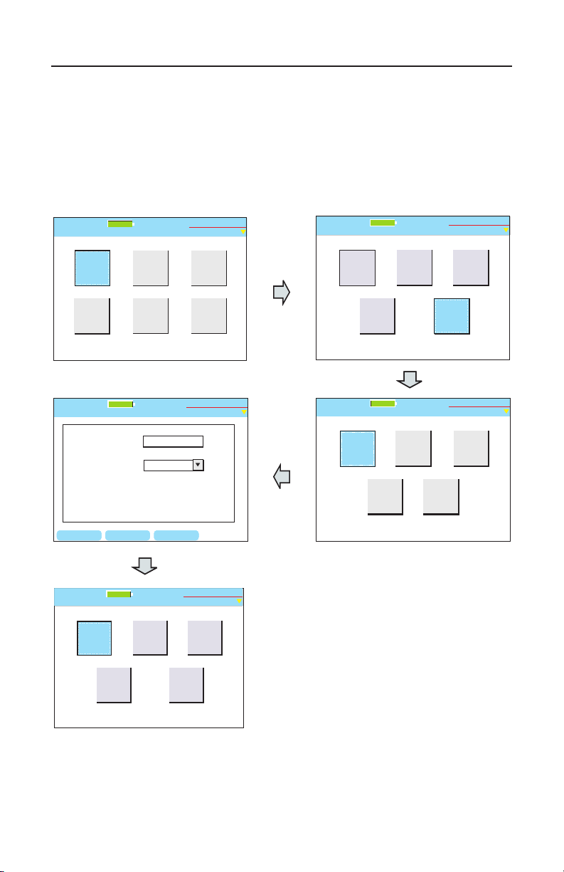
Creating the job in Plan-Um and uploading it to Validator-NT is generally
the quickest and easiest method of preparing your Cable List for testing.
Only Test Results associated with a job can be saved and downloaded to
Plan-Um for printing and archiving.
Figure 3.3 Creating a New Job Flow Chart
46
Page 48
Test-Um NT955 Series
Current Job
Untitled1.job
Site Info
Contractor
Info
Cable
Test
Schedule
Job Utilities
Custom
Cable
Definitions
Test-Um Inc.
validator
2005 Aug 25
10:53:01
100%
Current Job
Untitled1.job
Site Info
Contractor
Info
Cable
Test
Schedule
Job Utilities
Custom
Cable
Definitions
Test-Um Inc.
validator
2005 Aug 25
10:53:01
100%
BACKSPC DELETE
Site Info
Untitled1.job
Company:
Job ID:
Contact:
Phone:
Address 1:
Email:
Address 2:
State:
City:
Test-Um Inc.
validator
100%
2005 Aug 25
10:53:01
050825
Residential Site
John Homemaker
(555) 777-8888
8769 Generic Street
Springfield
MS
BACKSPC DELETE
Site Info
Untitled1.job
Company:
Job ID:
Contact:
Phone:
Address 1:
Email:
Address 2:
State:
City:
Test-Um Inc.
validator
100%
2005 Aug 25
10:53:01
050825
Residential Site
John Homemaker
(555) 777-8888
8769 Generic Street
Springfield
MS
ValidatorTM Managing Job FilesValidatorTM Managing Job Files
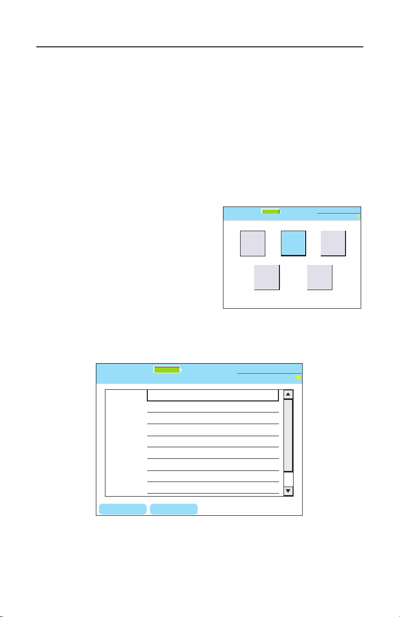
3.2. Creating Job Information
Job Information consists of Contractor Information and Site
Information. Contractor Information identies contact information for the
company performing the job. Site information contains information about
the site you are designing. (Figure 3.4)
Site and Contractor information prints on all job reports, and is used for
bidding and invoicing.
1. Select Auto Test from the start screen.
2. Select Site Info or
Contractor Info to enter into
the screens.
3. Use the alphanumeric keypad
to enter information into the
elds. Use the Backspace
(F1) and Delete (F2) soft keys
to edit and delete data.
4. Press Quit to exit the screen
when nished.
Figure 3.4 Creating Job Information
47
Page 49
Test-Um NT955 Series
BACKSPC
Current File:
New Template:
Export
Untitled1.job
Untitled1.job
DELETE OK
Test-Um Inc.
validator
100%
2005 Aug 25
10:53:01
BACKSPC
Current File:
New Template:
Export
Untitled1.job
Untitled1.job
DELETE OK
Test-Um Inc.
validator
100%
2005 Aug 25
10:53:01
ValidatorTM Managing Job FilesValidatorTM Managing Job Files
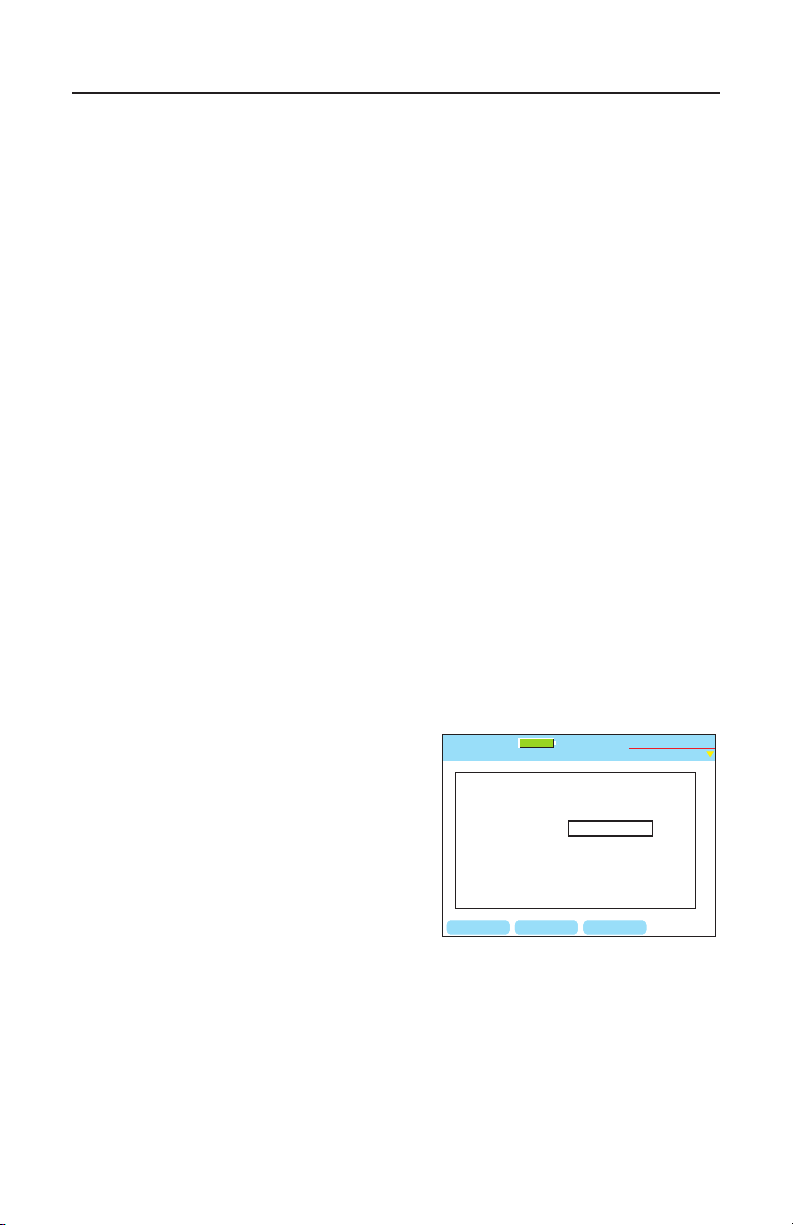
3.3. Creating Template Information
The purpose of the Template le (*.tut le) is to avoid reentering
Company Information and/or Custom Cable Denitions for each job by
saving the information in a Template that can be used on multiple jobs.
You can also use an existing Job to create a Template.
Test-Um recommends creating one or more reusable Template les (*.tut
les) when you perform the initial setup on your Validator-NT. Each time
you create a New Job select the template that you created and make
changes to the information as necessary.
The most efcient way to create templates is by using the Plan-Um
software. See the section of the Plan-Um instruction booklet titled
Managing Job Files/Save and Export As Template for complete
instructions. Template les can be created and stored in Plan-Um
and uploaded to the Validator-NT as needed, or created directly in the
Validator-NT.
1. To enter Template Information using the Validator-NT keypad,
select Auto Test on the Start screen. Enter the Contractor and/or
Custom Cable Information that you wish to save as a template.
Press Quit to return to the Auto Test screen.
2. Select Job Utilities and navigate to the Export Tut button.
3. Use the alphanumeric keypad
to name the Template. Use the
Backspace (F1) and Delete
(F2) soft keys to edit the name
as required. Press Accept to
complete the name. Press
OK (F3) soft key to save the
template information under the
name entered.
Figure 3.5 Exporting to a TemplateFigure 3.5 Exporting to a Template
4. The Template Information that you created contains contractor
and/or custom cable information associated with the current job.
You can use this template as it is or edit the information when
loaded into other jobs. You can also use an existing Job to create
a Template.
48
Page 50
Test-Um NT955 Series
Filename:
Template File:
New File
Untitled1.job
Default.tut
DELETE OKBACKSPC
Test-Um Inc.
validator
100%
2005 Aug 25
10:53:01
Example
Default.tut
Template01.tut
Template02.tut
ValidatorTM Managing Job FilesValidatorTM Managing Job Files
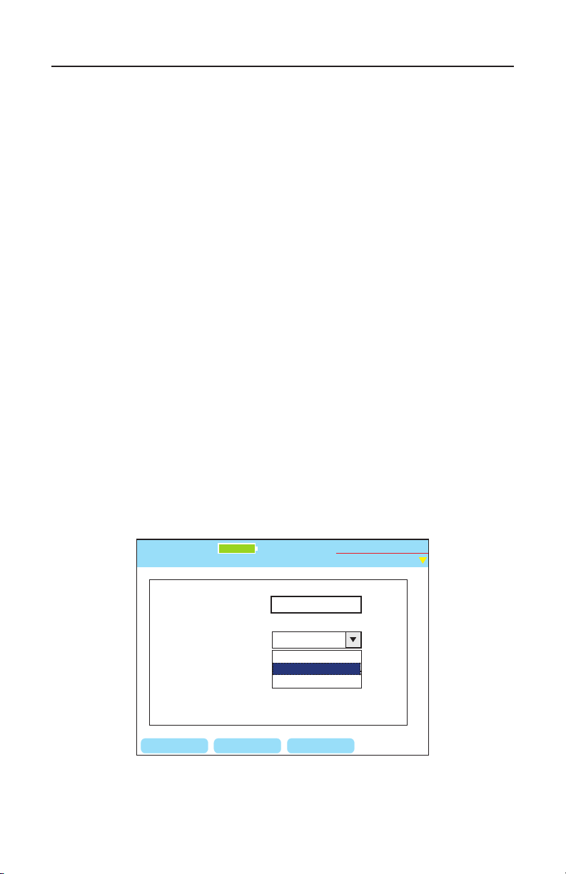
3.4. Using Template Files
Each time you create a New Job, select a previously created template
with Contractor Information and/or Custom Cable Denitions to avoid
reentering information. (Figure 3.6)
1. From the Start screen, select Auto Test.
2. Using the arrow key, navigate to Job Utilities and press
Select.
3. On the Job utilities screen, select New.
4. Enter a name for your job in the Filename box using the
alphanumeric keypad. Press Accept. You must create a
Filename. If you do not create a new Filename a Warning
Message appears advising that the “Filename is empty.”
Press OK to go back and create a Filename for the job.
5. Press Select to display the existing template les.
6. Select a template that has been previously created or select
Default for a blank template.
7. Press OK (F3) when nished. Your new job that has been
created will be your current job.
Figure 3.6 Selecting a Template File
49
Page 51

Test-Um NT955 Series
3.5. Step By Step Instructions for Creating a New Job
1. From the Start screen, select Auto Test.
2. Using the arrow key navigate to Job Utilities and press Select.
3. On the Job Utilities screen, select New.
4. Enter a Filename using the alphanumeric keypad. (Figure 3.3)
Press Accept. Depress the respective key multiple times to
scroll through the alpha and numeric options. If the subsequent
alphanumeric character is on the same key, you must use
the right arrow key to navigate to the next space. When the
subsequent letter is on a different key the cursor automatically
advances to the next space. The number one (1) key contains
the following special characters: @ ( ) - . , space. The Filename
you create will reside in the Job Manager.
5. You must create a Filename. If you do not create a new
Filename a Warning Message appears advising that the “File
name is empty”. Press OK to go back and create a Filename for
the job.
ValidatorTM Managing Job FilesValidatorTM Managing Job Files
6. Select a Template on the New File Screen. The default template
is blank. If you have previously created a Job Info template with
your company contact information, press the down arrow and
select it now. Press Accept to conrm your selection.
7. Press the OK (F3) soft key.
8. The Auto Test screen appears. Using the arrow keys navigate to
the Site Info button.
9. Enter Site Info using the alphanumeric keypad. Press Accept to
advance to the next eld.
10. If you have selected a template with your company information,
it will automatically appear in the Contractor Info eld. If you
have not selected a template, enter Contractor Info using the
alphanumeric keypad. Press Accept to complete each entry
eld.
50
Page 52

Test-Um NT955 Series
11. When all elds have been completed, press Quit. The Auto Test
screen reappears.
12. Select Cable Test Schedule. Using the alphanumeric keypad
create a Test Schedule by completing the Cable ID eld and
selecting a Cable Type from the drop down menu. The To
and From elds are optional information. The Result eld is
automatically populated when tests are run on that cable.
13. Proceed to Test by connecting the appropriate cable assembly.
ValidatorTM Managing Job FilesValidatorTM Managing Job Files
51
Page 53

Test-Um NT955 Series
ValidatorTM How AutoTest WorksValidatorTM How AutoTest Works
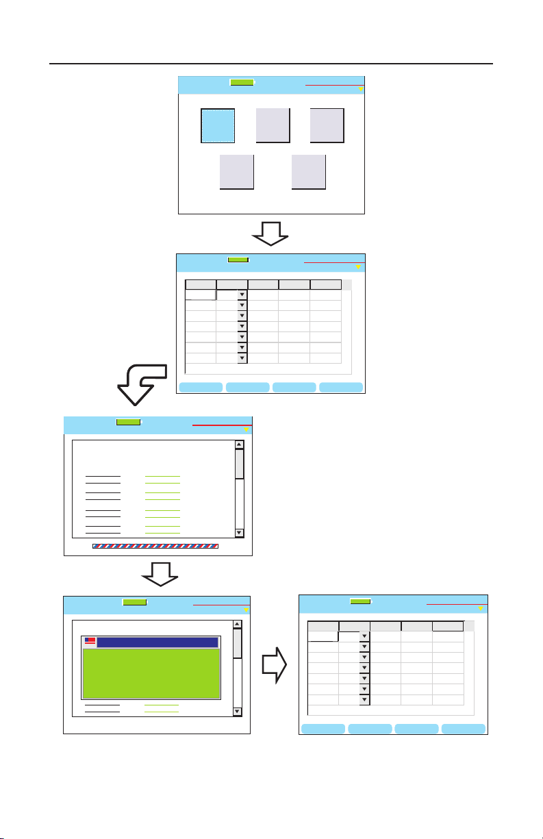
4. How Auto Test Works
Creating the Cable Test Schedule in Plan-Um, uploading it to the
Validator, and running Auto Test is the easiest and most efcient way
to verify cables. See the Uploading/Downloading Jobs section of this
manual (or the Plan-Um Software Instructions) for detailed instructions
on how to upload and download job information and test results between
Plan-Um and the Validator.
When you have uploaded a job from Plan-Um to the Validator-NT main
unit, the job will appear in the list on the Job Manager screen. To run an
existing job, you must rst open it from the Job Manager before using it
with Auto Test.
When you open a job, the Auto Test screen appears. This screen gives
you ve options: Cable Test Schedule, Site Information, Contractor
Information, Custom Cable Denitions and Job Utilities. See Figure
4.1 for a Flowchart of the Auto Test process.
52
Page 54
Test-Um NT955 Series
Current Job
Untitled1.job
Site Info
Contractor
Info
Cable
Test
Schedule
Job Utilities
Custom
Cable
Definitions
Test-Um Inc.
validator
2005 Aug 25
10:53:01
100%
RESULTS DEL CBL ADD CBLSORT
ID Type To
Cable001
Cable002
Cable003
Cable004
Cable005
Cable006
Cable007
CAT3
CAT5
From Result
CAT5E
RG-6
CAT5E
CAT5E
CAT6
100
PASS
01Net01
01Net02
01Net03
01TV01
01Net04
01Net05
01Net06
Cable List
Untitled1.job
100%
Test-Um Inc.
validator
01Panel01
01Panel01
01Panel01
01Panel01
01Panel01
01Panel01
01Panel01
Vo
IP
2005 Aug 25
10:53:01
?
?
?
?
?
Test Results
Untitled1.job
Test-Um Inc.
validator
Expected Results
1 1
2 2
3 3
6 6
4 4
5 5
7 7
8 8
Cable001 Testing...
1 1
2 2
3 3
6 6
4 4
5 5
7 7
8 8
CAT5E
Test Time: 10/11/2004 10:53 A.M
Remote ID: 1
1 Gbit/s
100%
2005 Aug 25
10:53:01
Test Results
Untitled1.job
100%
Test-Um Inc.
validator
Expected Results
1 1
2 2
3 3
6 6
4 4
5 5
7 7
8 8
Cable001 Pass
1 1
2 2
3 3
6 6
4 4
5 5
7 7
8 8
Test Time: 10/11/2004 10:53 A.M
Test Results
PASS
2005 Aug 25
10:53:01
RESULTS DEL CBL ADD CBLSORT
ID Type To
Cable001
Cable002
Cable003
Cable004
Cable005
Cable006
Cable007
CAT3
CAT5
From Result
CAT5E
RG-6
CAT5E
CAT5E
CAT6
100
PASS
01Net01
01Net02
01Net03
01TV01
01Net04
01Net05
01Net06
Cable List
Untitled1.job
100%
Test-Um Inc.
validator
01Panel01
01Panel01
01Panel01
01Panel01
01Panel01
01Panel01
01Panel01
Vo
IP
2005 Aug 25
10:53:01
?
?
?
?
1000
Vo
IP
RESULTS DEL CBL ADD CBLSORT
ID Type To
Cable001
Cable002
Cable003
Cable004
Cable005
Cable006
Cable007
CAT3
CAT5
From Result
CAT5E
RG-6
CAT5E
CAT5E
CAT6
100
PASS
01Net01
01Net02
01Net03
01TV01
01Net04
01Net05
01Net06
Cable List
Untitled1.job
100%
Test-Um Inc.
validator
01Panel01
01Panel01
01Panel01
01Panel01
01Panel01
01Panel01
01Panel01
Vo
IP
2005 Aug 25
10:53:01
?
?
?
?
1000
Vo
IP
ValidatorTM How AutoTest WorksValidatorTM How AutoTest Works
Figure 4.1 Auto Test Flowchart
53
Page 55
Test-Um NT955 Series
6
MNO
JKL
5
4
GHI
*
7
PRS
0
#
9
TUV
8
QZ
WXY
M
E
N
U
1
A
C
C
P
T
T
E
S
T
3
ABC
2
DEF
SEL
Q
U
I
T
VALIDATOR-NT
TM
OPEN RENAME
COPY
DEL JOB
Job Manager
Untitled1.job
Test-Um Inc.
validator
File Name Modified File Size
Test-um.job
Technicolor.job
Untitled1.job
10.21 Wed 2005 Oct 06
9.51 Fri 2005 Oct 08
10.00 Mon 2005 Oct 11
25.1 K
11.7 K
5.7 K
Magicworld.job
13.17 Tue 2005 Oct 05
13 K
100%
2005 Aug 25
10:53:01
ValidatorTM How AutoTest WorksValidatorTM How AutoTest Works
4.1. Cable Test Schedule
The Cable Test Schedule displays all the individual cable runs associated
with the open job. For your convenience when testing, you can sort each
eld in the Cable Test Schedule in ascending or descending order. To
sort the Cable Test Schedule, move the highlight to a cell in the column
to be sorted and press the SORT (F4) soft key. The column is sorted
rst in ascending order. A second press sorts by descending order and
toggles between the two on subsequent presses.
To test a cable on the list, highlight the Cable ID you wish to test. Attach
that cable to the appropriate connector on the main unit. Attach the
remote unit to the other end of the cable you wish to test.
With the remote connected to the cable, the test function can be started.
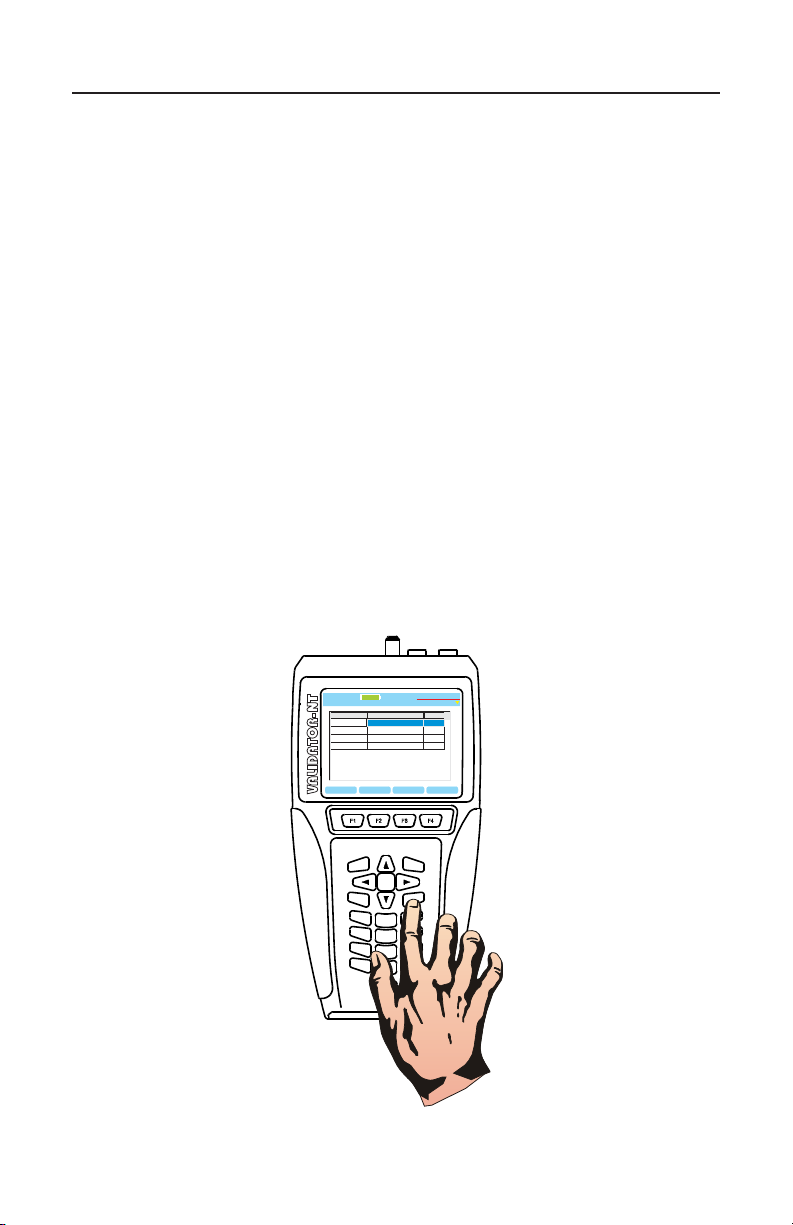
Press TEST (See Figure 4.2). You will hear relays switching in the main
unit and remote. A link is established with the remote, and Validator-NT
begins testing the cable to the parameters that have been dened for its
type. If it is network cable, Validator-NT will perform full Signal to Noise
Ratio and Skew testing as well as Speed testing with a Bit Error Rate
Test (BERT) in approximately 23 seconds.
Figure 4.2 Test Button
54
Page 56
Test-Um NT955 Series
Test Results
Untitled1.job
Expected Results
1 1
2 2
3 3
6 6
4 4
5 5
7 7
8 8
Cable001 Fail
1 1
2 2
3 3
6 6
4 4
5 5
7 7
8 8
Test Time: 10:53 Thu 2005 Aug 25
BACKSPCPG UP PG DOWN
Test-Um Inc.
validator
100%
2005 Aug 25
10:53:01
CAT5E
1 Gbit/s
Remote ID: 1
ValidatorTM How AutoTest WorksValidatorTM How AutoTest Works
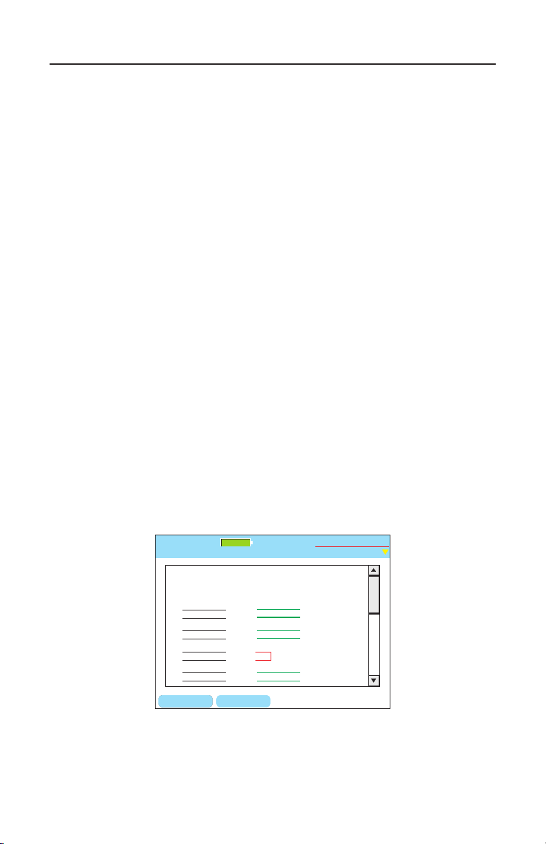
A PASS or FAIL indication will be briey displayed along with a speed
rating up to 1 Gigabit depending on the cable type. The screen will show
the Remote ID, wiremap of the individual pairs, and automatically scroll
down to display Length, Skew, SNR and BERT test results. The lights on
the remote unit ash sequentially to indicate a PASS condition. The job
le is saved after every Auto Test.
Then the Cable Test Schedule displays the results and the test highlight
automatically increments to the next cable in the list. The Voice over
IP icon (VoIP) displays if the cable test results indicate a speed rating
of 100MB or greater. You can go back to the previously tested cable
by using the arrow navigation buttons and the Results soft key (F2) to
inspect the specic test measurements, the speed test results, and the
wire map conditions of each individual pair on the cable. Use the Arrow
keys to scroll down this screen.
Interpreting Wiremap Errors: The following four classes of wiring
errors cause cables to FAIL. Errors are reported in order of severity. The
severity refers to the ability of a more severe error to mask lower severity
errors. For example, if there is a short in the cable, miswires and split
pairs may be detected for the pairs involved in the short fault.
Short - The pair has a low resistance connection between wire pairs or
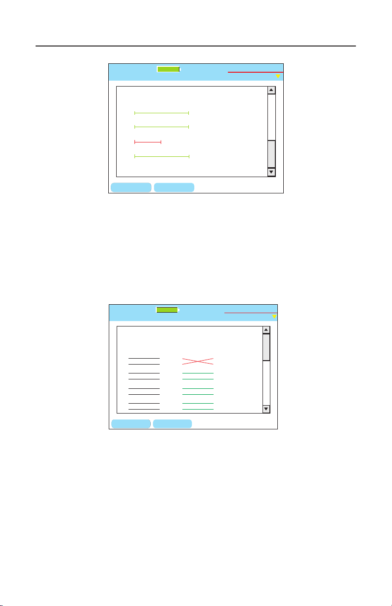
the shield. The wire pairs involved and the distance to the short in feet or
meters displays in red on the wiremap screen.
(See Figure 4.3 & Figure 4.4)
Figure 4.3 Test Results Short on Pair 4 and 5
55
Page 57
Test-Um NT955 Series
Test Results
Untitled1.job
Test-Um Inc.
validator
A
B
C
D
BERT Results:
188ft
186ft
--
--
--
--
Length
Max: 300ft
Skew
Max: 35ns
SNR
Min:20db
BACKSPCPG UP PG DOWN
--
--
30.0
30.0
Short
100%
2005 Aug 25
10:53:01
184ft
7 ft
Test Results
Untitled1.job
Expected Results
1 1
2 2
3 3
6 6
4 4
5 5
7 7
8 8
Cable001 Fail
1 1
2 2
3 3
6 6
4 4
5 5
7 7
8 8
Test Time: 10:53 Thu 2005 Aug 25
BACKSPCPG UP PG DOWN
Test-Um Inc.
validator
100%
2005 Aug 25
10:53:01
CAT5E
1 Gbit/s
Remote ID: 1
ValidatorTM How AutoTest Works
Figure 4.4 Page Down to Display Distance To Short
Miswire - A wire or both wires of a pair are not connected to correct
pins at the other end of the cable. For example, a reverse pair displays
the wires connected to the correct pair of pins, but the two leads are
reversed. (See Figure 4.5)
Split Pair - The cable has an error in the twisting of the wires together
within the cable. Cables are generally made up of 8 wires twisted
together in 4 pairs. A cable can be wired with correct continuity, but
not with correct pairing. If the only error is a split pair error, the cable
has correct continuity. If the Validator main unit is unable to link to its
remote due to another error, such as a short, A Link Test Error Message
displays “Unable to Measure SNR.” Press OK to view the wiremap
results. (See Figure 4.6)
Figure 4.5 Test Results-Miswire
56
Page 58
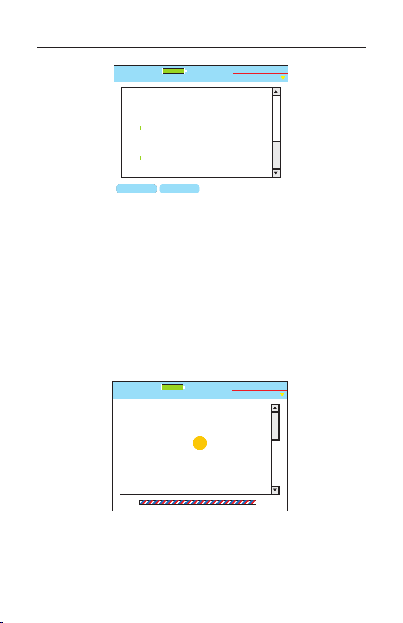
Test-Um NT955 Series
Test Results
Untitled1.job
Test-Um Inc.
validator
A
B
C
D
BERT Results:
Split
188ft
186ft
--
--
--
--
Length
Max: 300ft
Skew
Max: 35ns
SNR
Min:20db
BACKSPCPG UP PG DOWN
--
--
--
--
Split
100%
2005 Aug 25
10:53:01
Test Results
Untitled1.job
Test-Um Inc.
validator
Alternating Tone and Test.
REMOTE NOT FOUND
Cable001
100%
2005 Aug 25
10:53:01
ValidatorTM How AutoTest Works
Figure 4.6 Test Results-Split
Auto Find Feature: It is necessary to connect the Validator-NT remote
unit to the other end of the cable to measure for both Speed and
Performance. If the remote is not plugged in a message will appear
“Remote not found. Alternating between Tone and Test.” We call this
“Auto Find” and it is a feature that let’s you start the test and then go to
the other end where the remote should be plugged in. If the end of the
cable being tested is not known Validator-NT helps by generating tone
on the line so that a tone probe can be used to locate the far end of the
cable. Auto Find will terminate when the remote is plugged in.
Figure 4.7 Cable Test without Remote
57
Page 59
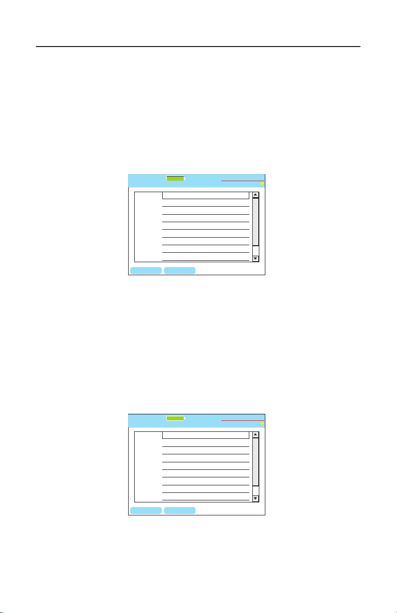
Test-Um NT955 Series
BACKSPC DELETE
Site Info
Untitled1.job
Company:
Job ID:
Contact:
Phone:
Address 1:
Email:
Address 2:
State:
City:
Test-Um Inc.
validator
100%
2005 Aug 25
10:53:01
BACKSPC DELETE
Contractor Info
Untitled1.job
Installer:
Company:
Phone:
Email:
Address 1:
Zipcode:
Address 2:
State:
City:
Test-Um Inc.
validator
100%
2005 Aug 25
10:53:01
ValidatorTM How AutoTest Works
4.2. Site Info
The next button on the Auto Test sub-menu is Site Info. This button
displays the Customer Contact Information associated with the job you
have selected for testing. By highlighting and selecting a eld you can
update or change the information in each eld, i.e.; Job ID, Contact
name, etc. Press Accept to accept the changes that were made and exit
that eld. To save text press Menu, scroll to Save Job, and press Select.
Figure 4.8 Customer Contact Information
4.3. Contractor Info
The next button is Contractor Info. Information on this screen can be
added or changed in the same manner as on the Site Info screen.
Figure 4.9 Contractor Information
58
Page 60

Test-Um NT955 Series
4.4. Custom Cable Denitions
The Custom Cable Denitions screen shows all dened cable types
loaded into the Validator-NT from the current job and what category
of test is performed on each type. The soft keys, F1 thru F3, allow for
adding, editing, and deleting cable information. (Figure 4.10)
The recommended procedure is to create Custom Cable Denitions in
Plan-Um and upload them to Validator-NT. However, by following the
steps outlined below you can also create Custom Cable Denitions and
Save them directly in your Validator-NT.
Custom Cable Types will only be saved to the current job unless you
create a Template File to store and retrieve this information.
1. Select Auto Test from the Start screen. Select Custom Cable
Denitions.
2. Modify a default cable type or select New using the soft keys.
Select Cable Type: Data, Phone, or 2-wire.
3. To create a New Custom Cable Denition, use the alphanumeric
keypad to enter the information into each eld. Press Accept
when you are nished entering data into each eld and to
advance to the next eld. You may also use the arrow keys on
your keypad to navigate between elds. Backspace and Delete
soft keys are provided to facilitate editing of information.
ValidatorTM How AutoTest Works
4. To edit an existing cable denition, use the alphanumeric keypad
to modify the test parameters in each eld. Press Accept or use
the arrow keys to advance to the next eld.
5. Length constant is used to calculate length measurements and
may be adjusted for custom cable types depending upon their
capacitance rating. Figure 5.1 displays typical cable length
parameters.
6. Typical settings for custom cable types will include a Minimum
SNR of 20 dB and Maximum SKEW of 35 nanoseconds on
Ethernet cable rated for gigabit speed.
7. Wire Mapping, Pair Polarities, and Split Test selections are
available using the drop down menus.
59
Page 61

Test-Um NT955 Series
8. To save the custom test parameters you have entered, press the
Save Type soft key (F3).
9. A message box appears that asks you to conrm the changes
in the test parameters you have entered. If you are sure of the
changes press Yes. To verify or edit or changes, repeat steps 4
through 7.
ValidatorTM How AutoTest Works
60
Page 62
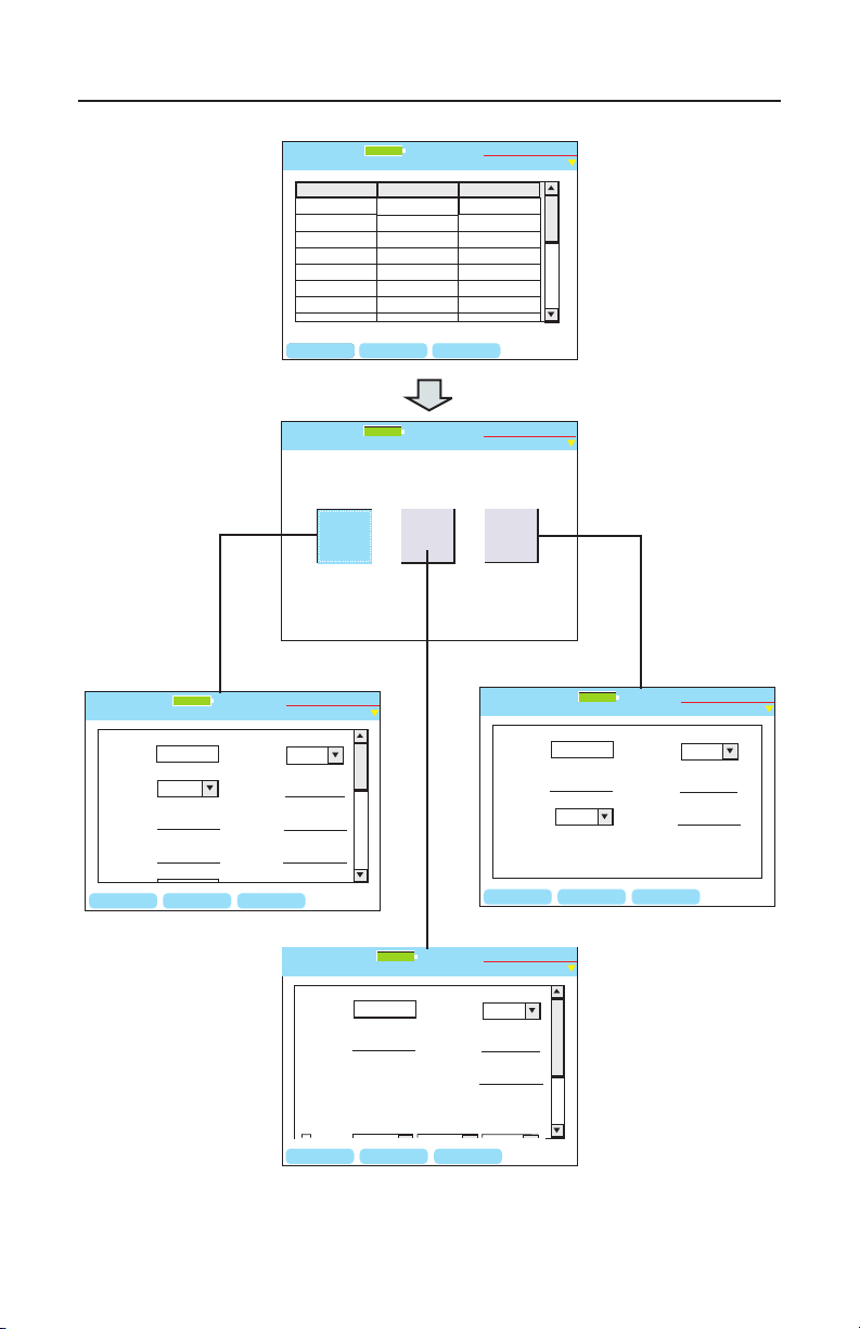
Test-Um NT955 Series
BACKSPCNEW EDIT DEL TYP
Type Name Category Default
CAT5
CAT5E
CAT6
CAT3_4P
CAT3
CAT3_2P
RG-6
Fire
Data
Data
Data
Phone
Phone
Phone
2 Wire
2 Wire
Yes
Yes
Yes
Yes
Yes
Yes
Yes
Yes
Type Table Screen
Untitled1.job
Test-Um Inc.
validator
100%
2005 Aug 25
10:53:01
Two-Wire
Type
Phone
Type
Data
Type
Test Definitions
Untitled1.job
Test-Um Inc.
validator
100%
2005 Aug 25
10:53:01
BACKSPC DELETE
Data Test Parameters
Untitled1.job
Speed:
Type Name
Skew:
SNR:
PF / ft.:
Length:
Mx Lngth( ft ):
Connector:
None
Yes
SAVE TYPE
Test-Um Inc.
validator
100%
2005 Aug 25
10:53:01
BACKSPC DELETE
Two Wire Test Parameters
Untitled1.job
Type Name
Length:
Mx Length(ft):
Connector
Yes
SAVE TYPE
pF/ft:
Normal
Polarity:
Test-Um Inc.
validator
100%
2005 Aug 25
10:53:01
BACKSPC DELETE
Phone Test Parameters
Untitled1.job
Type Name
In Use:
Length:
Mx Lngth (ft):
Connector
Yes
SAVE TYPE
pF/ft:
Map To:
Pair Polarities:
Split Test:
1-6 1-6 Don’t Care Yes
Test-Um Inc.
validator
100%
2005 Aug 25
10:53:01
ValidatorTM How AutoTest Works
Figure 4.10 Custom Cable Flowchart
61
Page 63
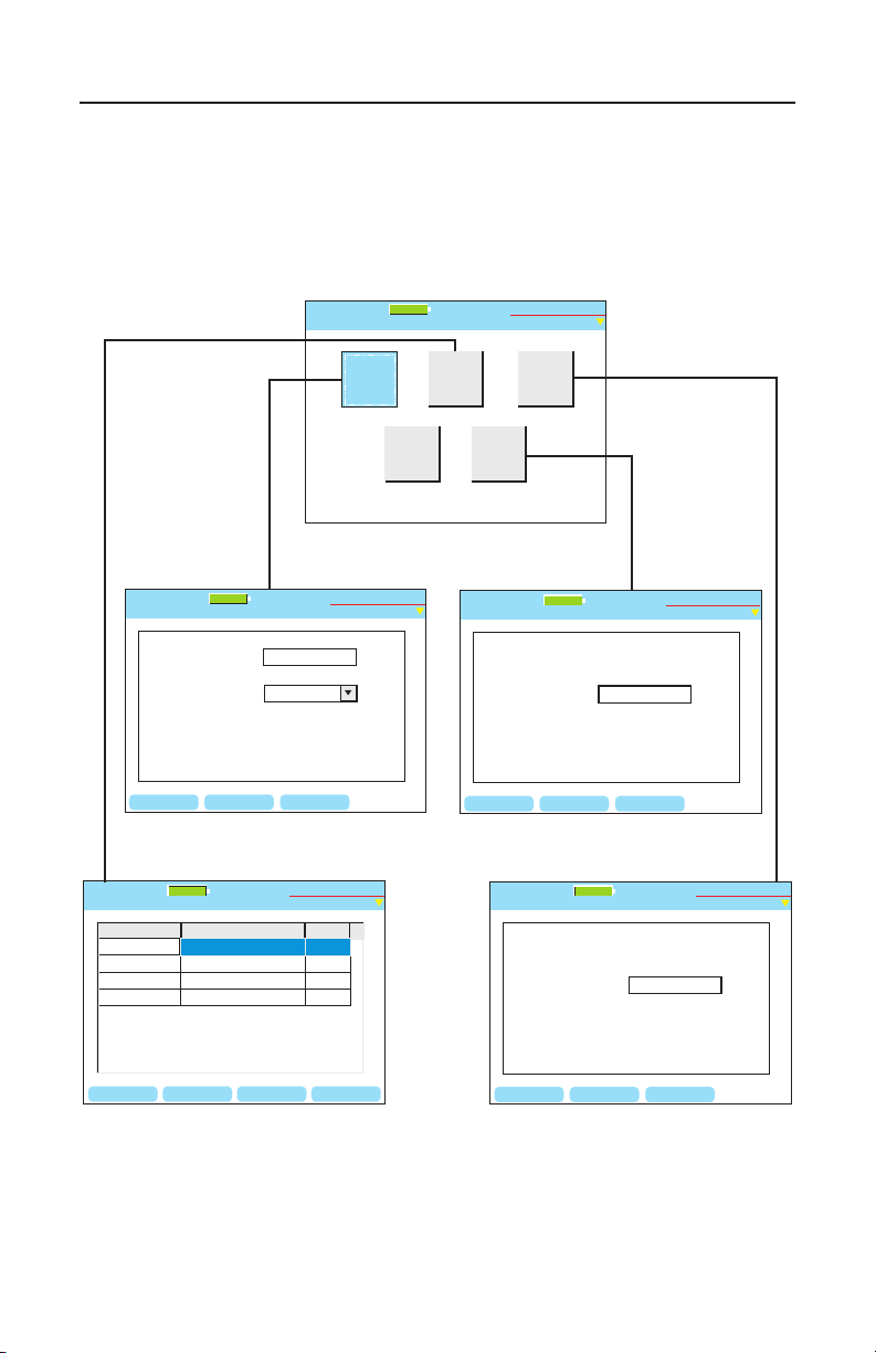
Test-Um NT955 Series
Export Tut
Open
New
Job Utilities
Untitled1.job
Save As
Save
Test-Um Inc.
validator
100%
2005 Aug 25
10:53:01
Filename:
Template File:
New File
Untitled1.job
Default.tut
DELETE OKBACKSPC
Test-Um Inc.
validator
100%
2005 Aug 25
10:53:01
Example
BACKSPC
Current File:
New File:
Save As
Untitled1.job
Untitled1.job
DELETE OK
Test-Um Inc.
validator
100%
2005 Aug 25
10:53:01
OPEN RENAME
COPY
DEL JOB
Job Manager
Untitled1.job
Test-Um Inc.
validator
File Name Modified File Size
Test-um.job
Technicolor.job
Untitled1.job
10.21 Wed 2005 Oct 06
9.51 Fri 2005 Oct 08
10.00 Mon 2005 Oct 11
25.1 K
11.7 K
5.7 K
Magicworld.job
13.17 Tue 2005 Oct 05
13 K
100%
2005 Aug 25
10:53:01
BACKSPC
Current File:
New Template:
Export
Untitled1.job
Untitled1.job
DELETE OK
Test-Um Inc.
validator
100%
2005 Aug 25
10:53:01
ValidatorTM How AutoTest WorksValidatorTM How AutoTest Works
4.5. Job Utilities
The last button on the Auto Test menu is Job Utilities. This screen has
buttons to allow creation of a new job le, open an existing job le on
the CF card, export a template le, save the le that is currently open, or
save an open le as a le with a new name (Figure 4.11)
Figure 4.11 Job Utilities Flowchart
62
Page 64

Test-Um NT955 Series
4.6. Step by Step Instructions for Performing Auto Tests
1. From the Start Menu, navigate to the Job Manager using the
arrow keys which move from left to right on each row.
2. Select the Job you wish to test. Press Open.
3. The Auto Test screen is presented with the Cable Test Schedule
button highlighted. Press Select to view the Test Schedule.
Press the up and down arrows to highlight the cable to be tested.
4. Using the appropriate cable assembly and jacks, connect the
Validator-NT main unit to one end of the cable and the remote
unit to the opposite end of the rst cable identied in the Test
Schedule.
Note: The Wiremapping Remotes (TP610) test wiremapping only and
are NOT designed to work in the Auto Test mode. The Test Results will
indicate Fail because the Validator was not able to perform a complete
test sequence.
5. Press Test.
ValidatorTM Running Manual TestsValidatorTM Running Manual Tests
6. A message displays if the Main Unit is not communicating with
the Remote Unit. If the Remote unit is not found, the main unit
automatically sends tone on the cable. Using a Tone Tracer,
such as Test-Um’s TT100, locate the cable you wish to test.
Connect the Remote unit and testing will proceed.
7. Pass/Fail Test Results display, also indicating the speed the
cable is certied to perform at, and whether the cable will support
Voice over IP (VoIP).
8. The Validator-NT automatically increments to the next cable to
be tested.
9. Testing will proceed through the entire Cable Test Schedule
regardless of test failures.
63
Page 65

Test-Um NT955 Series
10. Press the Results (F2) soft key to display detailed test
information for the cable that is currently highlighted.
11. Pass test parameters display in green and fail parameters
display in red.
12. Test Results are automatically saved to the current job. To save
text changes, select Save Job.
13. Test Results for the selected job can then be downloaded to
laptop/ PC and an End of Job Report generated for billing.
ValidatorTM How AutoTest WorksValidatorTM How AutoTest Works
64
Page 66

Test-Um NT955 Series
ValidatorTM Running Manual TestsValidatorTM Running Manual Tests
5. Running Manual Tests
Manual Tests performs individual tests on Data, Phone, or 2-wire cables
based on dened test standards. The tests that can be performed for
each selected cable type are listed on the Manual Test screen for that
type (Figure 5.2).
5.1. Data Cables
Data Cables are dened as cables wired to T568A/B pin numbering and
pairing. Validator-NT will perform full Signal to Noise Ratio and Skew
testing as part of the cable test. Speed testing is done with the Bit Error
Rate Test (BERT). You can also send tone over the cable, check length,
ash a hub or do a Speed Test with BERT.
Note: The TP610 Remote Wiremappers are designed to report wiremap
length and Skew results only. A Link Test Error message appears
“Unable to Measure SNR.” To measure Signal to Noise Ratio you must
use the Validator Smart Remote unit.
Length Constant is used for length measurement and is adjusted in
.1pF increments by pressing the up and down arrow keys. The displayed
cable length is recalculated as the length constant is changed. This
allows an unknown length constant to be determined by attaching a
known length of cable and running the test. The length constant can
be varied up or down until the displayed length matches the measured
length. The displayed length constant is then the correct value for that
cable. This same adjustment feature is on both the Phone and 2-Wire
test screens. (Figure 5.1)
Cable Type pF/ft. pF/m
Data Cable
CAT3 19.0 62.5
CAT5/CAT5E/CAT6 15.0 49.0
Coaxial Cable
RG58 27.5 90.0
RG6, RG11, RG59 16.25 53.0
Security Wire
22AWG, Jacketed 24.0 78.5
22AWG, Unjacketed 14.0 46.0
20AWG, Unjacketed
16.0 52.5
18AWG, Unjacketed 17.0 55.5
Figure 5.1 Typical Cable Length Parameter
65
Page 67
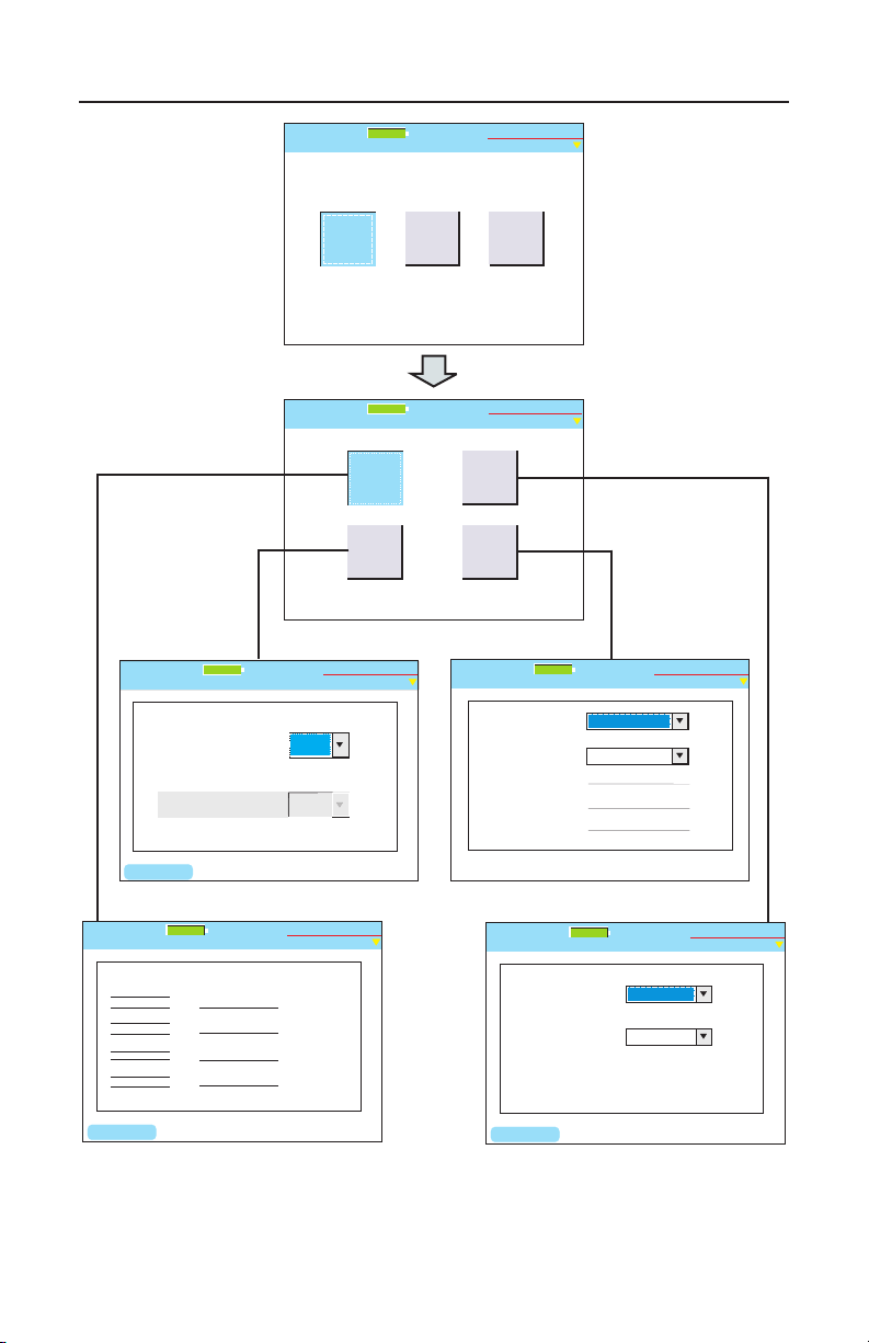
Test-Um NT955 Series
Test-Um Inc.
validator
100%
2005 Aug 25
10:53:01
2-Wire
Cable
Phone
Cable
Data
Cable
Cable Tests
Untitled1.job
Tone
Cable
Test
Data Manual Tests
Untitled1.job
BERT
Test
Hub
Flash
Test-Um Inc.
validator
100%
2005 Aug 25
10:53:01
Select Rate:
Hub Flash
Untitled1.job
Auto
NIC Wiring:
Flash Any, Auto
Any
FLASH
Test-Um Inc.
validator
100%
2005 Aug 25
10:53:01
O
Ethernet Speed:
Bits to Transfer:
BERT Test
Untitled1.job
1 Gbit/s
10 Gbits
% Completed:
Test Rate:
Error:
Test-Um Inc.
validator
100%
2005 Aug 25
10:53:01
Wiremap - DATA
Untitled1.job
Results Length Skew SNR
34ft
34ft
33ft
34ft
1 1
2 2
3 3
6 6
4 4
5 5
7 7
8 8
S S
Remote ID: 1 Length Constant: 15 PF/ft.
A 1.6 30.0
B 0.0 30.0
C 1.9 30.0
D 0.0 30.0
Up and Down controls Length Constant
LENGTH
Test-Um Inc.
validator
100%
2005 Aug 25
10:53:01
-X
SEND
Tone Sound:
Data Tone
Untitled1.job
High - Low
Tone Path:
Press send to begin.
all
Test-Um Inc.
validator
100%
2005 Aug 25
10:53:01
ValidatorTM Running Manual TestsValidatorTM Running Manual Tests
Figure 5.2 Data Manual Test Flowchart
66
Page 68
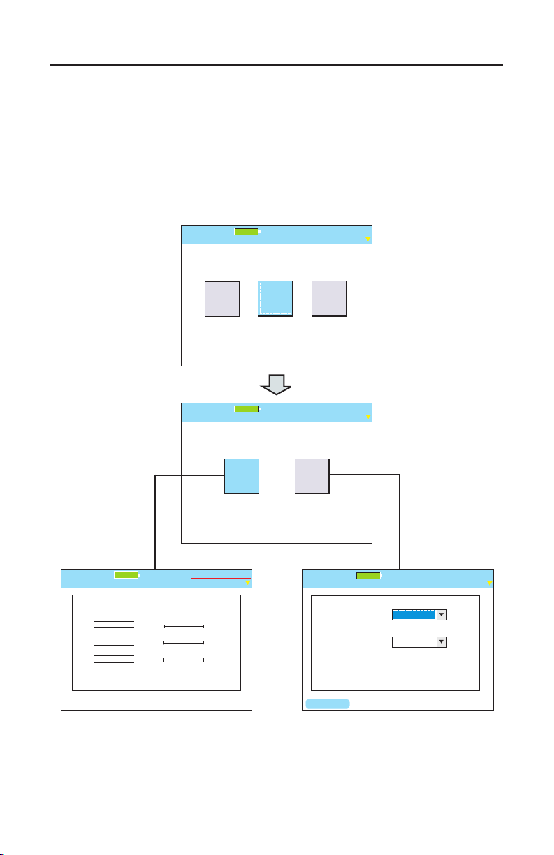
Test-Um NT955 Series
Test-Um Inc.
validator
100%
2005 Aug 25
10:53:01
2-Wire
Cable
Phone
Cable
Data
Cable
Cable Tests
Untitled1.job
Tone
Cable
Test
Phone Manual Tests
Untitled1.job
Test-Um Inc.
validator
100%
2005 Aug 25
10:53:01
Wiremap - PHONE
Untitled1.job
Wiremap Length
1 1
6 6
52 ft
50 ft
52 ft
2 2
5 5
3 3
4 4
Remote ID: 1 Length Constant: 15 PF/ft.
A
B
C
Up and Down controls Length Constant
Test-Um Inc.
validator
100%
2005 Aug 25
10:53:01
SEND
Phone Tone
Untitled1.job
Tone Sound:
High - Low
Tone Path:
Press send to begin.
all
Test-Um Inc.
validator
100%
2005 Aug 25
10:53:01
ValidatorTM Running Manual TestsValidatorTM Running Manual Tests
5.2. Phone Cables
Phone Cables are dened as cables wired to the USOC 3 pair standard
for pin numbering and pairing. The test shows opens, shorts and length
of the run. The wiremap and length measurements are displayed.
(Figure 5.3)
Figure 5.3 Phone Manual Test Flowchart
67
Page 69
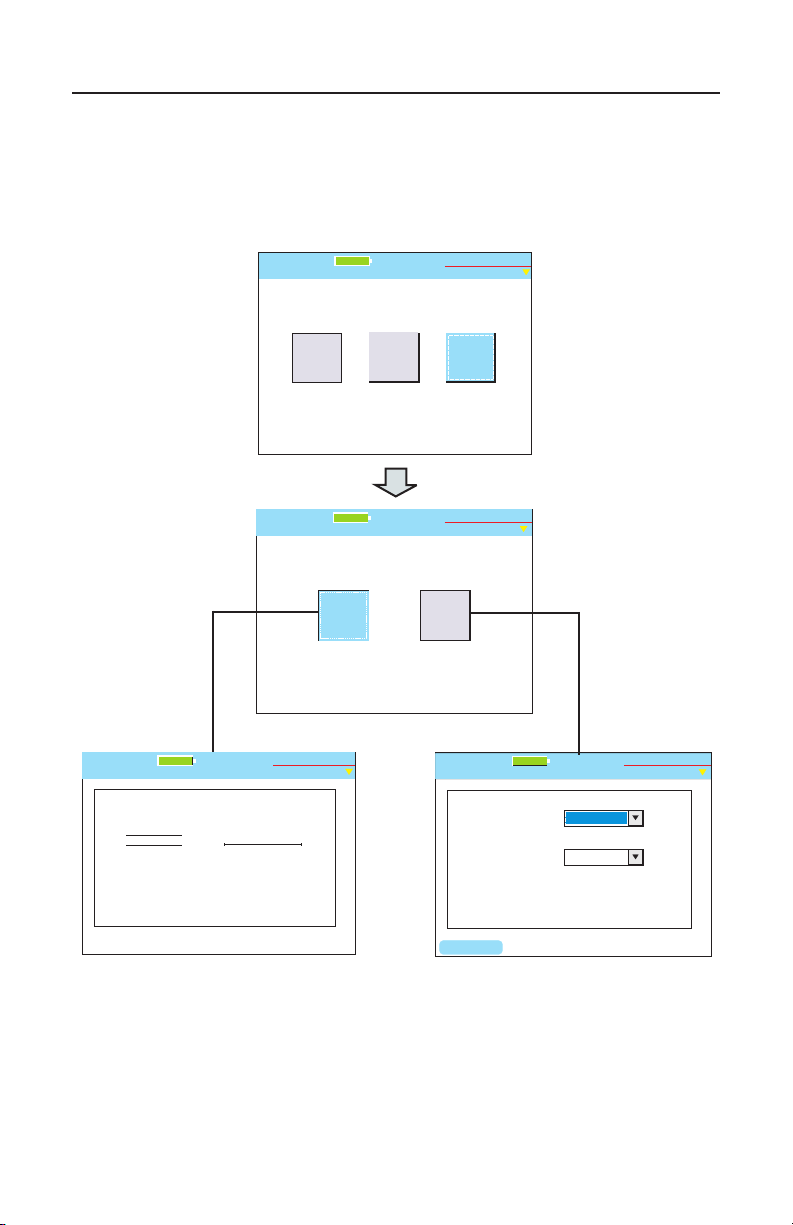
Test-Um NT955 Series
Test-Um Inc.
validator
100%
2005 Aug 25
10:53:01
2-Wire
Cable
Phone
Cable
Data
Cable
Cable Tests
Untitled1.job
2 Wire Manual Tests
Untitled1.job
Test-Um Inc.
validator
Tone
Cable
Test
100%
2005 Aug 25
10:53:01
2 Wire Length
Untitled1.job
Test-Um Inc.
validator
Wiremap Length
1 1
2 2
A
52 ft
Up and Down controls Length Constant
Remote ID: 1 Length Constant: 15 PF/ft.
100%
2005 Aug 25
10:53:01
SEND
2 Wire Tone
Untitled1.job
Test-Um Inc.
validator
Tone Sound:
High - Low
Tone Path:
Press send to begin.
all
100%
2005 Aug 25
10:53:01
ValidatorTM Running Manual Tests
5.3. 2-Wire Cables
2-wire cables are tested for wire map and length. You can also send tone
over the cable. (Figure 5.4)
Figure 5.4 Two Wire Manual Test Flowchart
68
Page 70
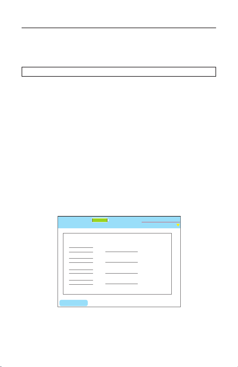
Test-Um NT955 Series
Wiremap - DATA
Untitled1.job
Results Length Skew SNR
34ft
34ft
33ft
34ft
1 1
2 2
3 3
6 6
4 4
5 5
7 7
8 8
S S
Remote ID: 1 Length Constant: 15 PF/ft.
A 1.6 30.0
B 0.0 30.0
C 1.9 30.0
D 0.0 30.0
Up and Down controls Length Constant
LENGTH
Test-Um Inc.
validator
100%
2005 Aug 25
10:53:01
-X
ValidatorTM Running Manual Tests
5.4. Step by Step Instructions for Performing Manual Tests
1. From the Start Menu, select Manual Tests. Choose Data, Phone
or 2-wire cable type.
Warning! Manual Test Results will NOT be saved.
2. Using the appropriate cable assembly and jacks, connect
the Validator-NT main unit to the cable identied in the Test
Schedule with the Remote Unit connected to the opposite end.
Cable Test
1. Select Cable Test to initiate a test sequence. The wiremap,
length, SNR, and Skew results will display. (Figure 5.5)
2. The up and down arrow keys adjust the length constant by .1
pF increments if the cable requires a different setting than that
displayed at the top of the screen.
3. On the DATA test screen, the Length (F1) soft key can be used
to run the length portion of the test sequence only, skipping the
Skew and SNR tests.
Figure 5.5 Manually Testing Cables
69
Page 71
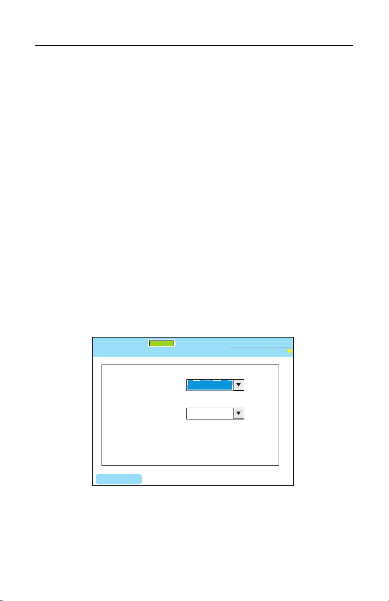
Test-Um NT955 Series
SEND
Tone Sound:
Data Tone
Untitled1.job
High - Low
Tone Path:
Press send to begin.
all
Test-Um Inc.
validator
100%
2005 Aug 25
10:53:01
ValidatorTM Running Manual Tests
Placing Tone On a Cable Pair
1. Select Manual Tests. Choose Data, Phone or 2-wire cable
type.
2. The Manual Test Menu for the cable type you selected displays.
3. Select Tone.
4. Select the desired Tone Sound. Press Accept. The cursor
moves to the Tone Path dialog box. (Figure 5.6)
5. Select the Tone Path by choosing the cable pair or pairs you
wish to apply Tone to. Press Accept.
6. Using the appropriate cable assembly, connect the cable to the
Main unit jacks.
7. Press the Send (F1) soft key to start the tone.
8. Using a Tone Tracer, such as Test-Um’s TT100, trace the tone.
Figure 5.6 Tone Generator
70
Page 72
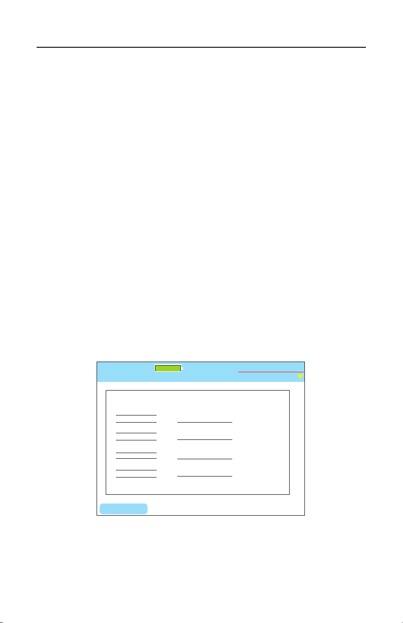
Test-Um NT955 Series
Wiremap - DATA
Untitled1.job
Results Length Skew SNR
34ft
34ft
33ft
34ft
1 1
2 2
3 3
6 6
4 4
5 5
7 7
8 8
S S
Remote ID: 1 Length Constant: 15 PF/ft.
A -- --
B -- --
C -- --
D -- --
Up and Down controls Length Constant
LENGTH
Test-Um Inc.
validator
2005 Aug 25
10:53:01
100%
ValidatorTM Running Manual Tests
Testing Cable Length
When you run Cable Test, length is reported in feet or meters. In
addition, the Manual Cable Test for data includes a quick independent
length test using the Length (F1) soft key. This test is useful to the
installer to determine how much cable is left on the reel or the length
of a cable run. Follow the procedure for Cable Tests described above.
(Figure 5.7)
1. Select Manual Tests. Choose Data, Phone or 2-wire cable type.
2. The Manual Test Menu for the cable type you selected displays.
3. Using the right arrow key, select Cable Test.
4. The pF+ (F1) and pF- (F2) soft keys adjust the length constant in
pico farads per unit length if the cable requires a different setting
than that displayed at the top of the screen.
5. Select the Length (F1) soft key.
6. The length of the cable pairs tested displays, as well as any
associated errors.
Figure 5.7 Testing Cable Length
71
Page 73
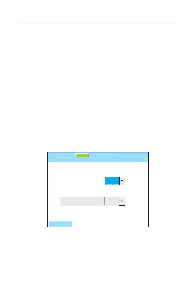
Test-Um NT955 Series
Select Rate:
Hub Flash
Untitled1.job
Auto
NIC Wiring:
Flash Any, Auto
Any
FLASH
Test-Um Inc.
validator
100%
2005 Aug 25
10:53:01
O
ValidatorTM Running Manual Tests
Hub Flash Test
This test sends a link signal to test for active Ethernet equipment. This is
the only test that runs with other Ethernet equipment.
1. From the Data Manual Test screen, select Hub Flash
2. From the drop down menu, select a specic data rate or Any if
you wish to have the hub and Validator-NT auto negotiate the
speed. (Figure 5.8)
3. In 10Mb or 100Mb mode, the Validator-NT can be set to emulate
a NIC, a HUB or to Auto (auto MDI/MDIX) mode using the drop
down menu. If plugging into a hub, the Validator-NT must be set
to NIC or Auto modes. The Auto mode can be used most of the
time, but it may be necessary to select Hub or NIC mode when
connecting to a network device that can “sleep” such as a laptop
computer to wake it up.
Figure 5.8 Hub Flash Test
72
Page 74
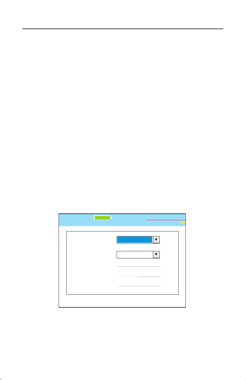
Test-Um NT955 Series
Ethernet Speed:
Bits to Transfer:
BERT Test
Untitled1.job
1 Gbit/s
10 Gbits
% Completed:
Test Rate:
Error:
Test-Um Inc.
validator
100%
2005 Aug 25
10:53:01
ValidatorTM Running Manual Tests
Performing a Bit Error Rate Test
A Bit Error Rate Test (BERT) sends data packets from the main unit to
the remote, measures speed and errors and correlates this to a PASS or
FAIL result. This test can only be run from end to end on a single cable, it
cannot be run through an Ethernet hub or switch.
1. From the Data Manual Tests screen, select the BERT Test
button. (Figure 5.9)
2. Using the drop down dialog box, select an Ethernet speed of 1
gigabit or 100 Megabits. Press Accept
3. Select the number of bits to transfer from the drop down dialog
box. Press Accept.
4. Press the Test button to begin the run. The % Complete will
advance as the test proceeds and any errors will be reported as
the % Completed is updated. A Pass or Fail will be displayed at
the end of the test based on the industry standard of not more
than one error in 10 Gigabits transferred.
Figure 5.9 Bit Error Rate Test
73
Page 75
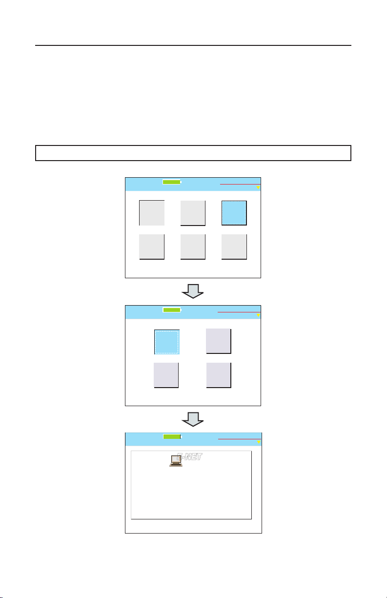
Test-Um NT955 Series
Start
Untitled1.job
100%
Test-Um Inc.
validator
2005 Aug 25
10:53:01
Manual
Tests
Network
Tests
Auto
Test
Setup
Properties
Job
Manager
Port
Discovery
Network Tests
Untitled1.job
2005 Aug 25
10:53:01
Test-Um Inc.
validator
100%
Cisco
Discovery
Protocol
Hub
Flash
Ping Test
Port Discovery
Ethernet
Capabilities
Link established at: 1 Gbs
Remote device MDI/MDI-X: Auto
Remote device advertises: 1 Gbs FDX
Remote device advertises: 100 Mbs HDX/FDX
Remote device advertises: 10 Mbs HDX/FDX
Pair [A]: skew: 0.0 ns SNR: 30.0 dB
Pair [B]: skew: 8.0 ns SNR: 29.9 dB
Pair [C]: skew: 0.0 ns SNR: 30.0 dB
Pair [D]: skew: 8.0 ns SNR: 30.0 dB
Frequency Offset: 30 ppm
Untitled1.job
Test-Um Inc.
validator
100%
2005 Aug 25
10:53:01
AUTO
E-NET
E-NET
ValidatorTM Network Tests
6. Performing Active Network Tests
Active Network Tests include four functional test areas designed to report
cable performance and verify connectivity to network devices: Port
Discovery, Ping, Cisco Discovery Protocol, and Hub Flash. Select
Network Tests from the Start menu to access Network Tests. Use the
RJ45 ports to perform these tests.
Warning! Active Network Test Results will NOT be Saved.
Figure 6.1 Port Discovery Network Test Flowchart
74
Page 76
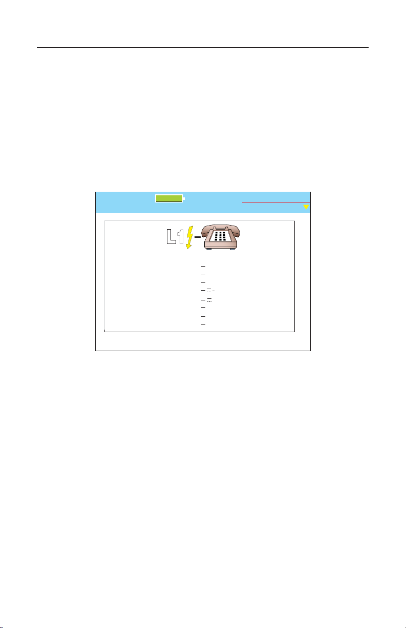
Test-Um NT955 Series
Port Discovery
Telephone
1
2
3
4
5
6
7
8
.
.
.
Untitled1.job
Test-Um Inc.
validator
2005 Aug 25
10:53:01
+
100%
L1
ValidatorTM Network Tests
6.1. Port Discovery
Port discovery identies telephone or network devices connected to the
other end of the jack or cable. The test begins with a search for voltages
that may be present. If voltages are found, the patterns for commonly
used services are compared to the voltages observed and reported as
phone, ISDN or legacy phantom power as appropriate. If the voltage
pattern is unknown, the port pin conditions are reported.
Figure 6.2 Phone Detected
75
Page 77
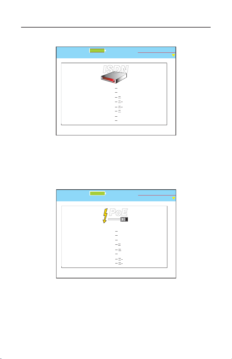
Test-Um NT955 Series
Port Discovery
ISDN
1
2
3
4
5
6
7
8
.
.
.
Untitled1.job
Test-Um Inc.
validator
2005 Aug 25
10:53:01
+
+
100%
ISDN
ISDN
Port Discovery
Legacy Power
over Ethernet
1
2
3
4
5
6
7
8
.
.
.
Untitled1.job
Test-Um Inc.
validator
2005 Aug 25
10:53:01
+
100%
PoE
PoE
+
ValidatorTM Network Tests
6.3 ISDN Phone Detected
6.4 Legacy Power Detected
76
Page 78
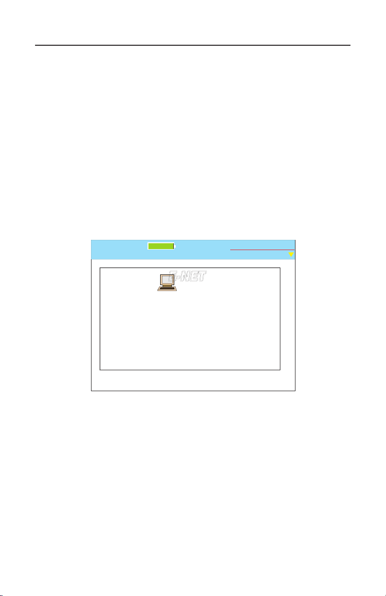
Test-Um NT955 Series
Port Discovery
Ethernet
Capabilities
Link established at: 1 Gbs
Remote device MDI/MDI-X: Auto
Remote device advertises: 1 Gbs FDX
Remote device advertises: 100 Mbs HDX/FDX
Remote device advertises: 10 Mbs HDX/FDX
Pair [A]: skew: 0.0 ns SNR: 30.0 dB
Pair [B]: skew: 8.0 ns SNR: 29.9 dB
Pair [C]: skew: 0.0 ns SNR: 30.0 dB
Pair [D]: skew: 8.0 ns SNR: 30.0 dB
Frequency Offset: 30 ppm
Untitled1.job
Test-Um Inc.
validator
100%
2005 Aug 25
10:53:01
AUTO
E-NET
E-NET
ValidatorTM Network Tests
If no telephone or voltage sources are found, Validator-NT attempts an
Ethernet link. If a link is found, information about the link is displayed:
- Identies the Ethernet connection
- Speed linked at (10, 100 or 1000 Megabit)
- Type of link (MDI, MDI-X or Auto MDI/MDI-X)
- Advertised Speed of the device
- SNR
- Skew if 1000 Mbit
- Frequency Offset – the difference in the data rate, in parts per
million (ppm), between the Validator-NT and the installed far end
equipment. The value should not normally exceed 100 ppm.
Data errors are likely to occur at 200 ppm.
Figure 6.5 Ethernet Link Detected
77
Page 79
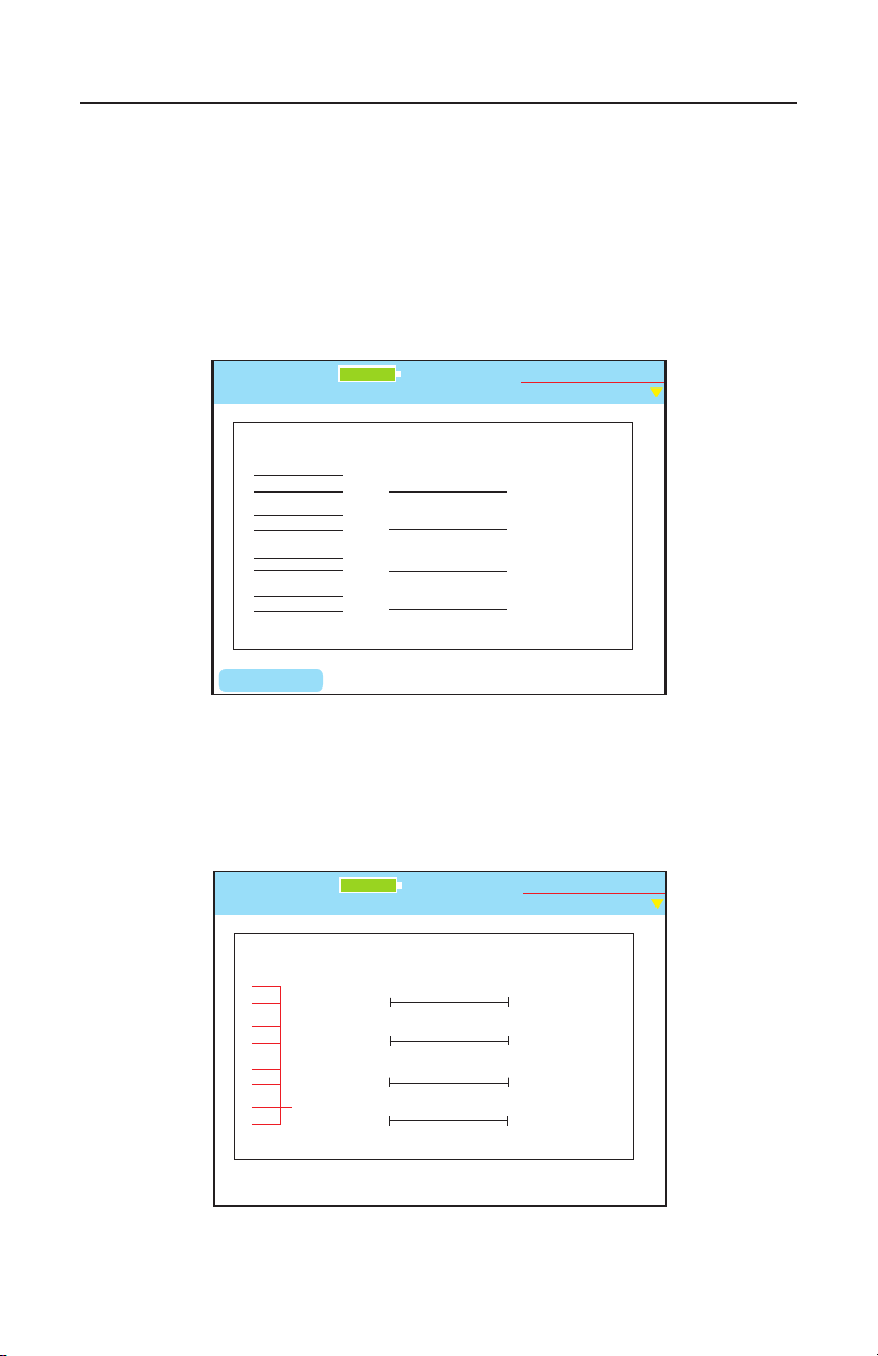
Test-Um NT955 Series
Wiremap - DATA
Untitled1.job
Results Length Skew SNR
34ft
34ft
33ft
34ft
1 1
2 2
3 3
6 6
4 4
5 5
7 7
8 8
S S
Remote ID: 1 Length Constant: 15 PF/ft.
A 1.6 30.0
B 0.0 30.0
C 1.9 30.0
D 0.0 30.0
Up and Down controls Length Constant
LENGTH
Test-Um Inc.
validator
100%
2005 Aug 25
10:53:01
-X
Wiremap - DATA
Untitled1.job
Results Length Skew SNR
20ft
20ft
20ft
20ft
1 1
2 2
3 3
6 6
4 4
5 5
7 7
8 8
S S
Possible Ethernet Length Constant: 15 PF/ft.
A -- --
B -- --
C -- --
D -- --
Up and Down controls Length Constant
Test-Um Inc.
validator
100%
2005 Aug 25
10:53:01
Short
Short
Short
Short
ValidatorTM Network Tests
If neither voltages nor Ethernet is detected, Validator-NT searches for its
remote to run a cable test. If the remote is found, a manual mode cable
test is run and the remote ID, wiremap, full Signal to Noise Ratio, and
Skew test results (1000Mbit only) are displayed. Speed testing, as well
as placing tone on a cable, is performed in the Manual Test mode of the
Validator-NT only. If a remote is not found, a one-ended test for shorts
and split pairs is run and the results are reported.
If the results appear to be un-powered Ethernet equipment, that is
reported as well.
Figure 6.7 Un-powered Ethernet Test
Figure 6.6 Data Cable Test
78
Page 80
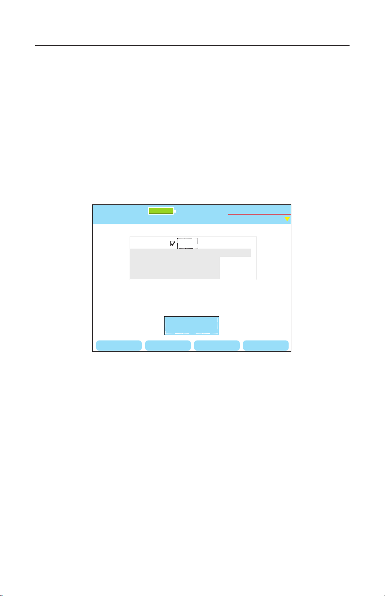
Test-Um NT955 Series
IP Address
Untitled1.job
2005 Aug 25
10:53:01
DNS
For manual IP address, uncheck DHCP. Netmask is count of 1 bits
GW/RTR
My IP
DHCP
192.168.1.200 / 24
My IP: 192.168.1.109
Netmask (CIDR): 255.255.255.0 (24)
Gateway/Router (GW/RTR): 192.168.1.1
Domain Name Server (DNS): 192.168.1.100
Get IP
Parameters
Test-Um Inc.
validator
DELETE TARGETSBACKSPC PINGTOOL
100%
ValidatorTM Network Tests
6.2. Ping Test
The Ping Test is used to verify connectivity to resources on or off the
network and IP addresses. The Ping Test will simultaneously Ping up
to seven different IP addresses and can be run in DHCP or manual
addressing modes.
In DHCP mode, the Validator-NT’s assigned address and the addresses
of the router/gateway and DNS server plus the net mask are obtained
automatically from a DHCP server and the values displayed on the
Validator-NT. Press Get IP Parameters to start the DHCP request
process.
Figure 6.8 DHCP Mode Ping Test Results
79
Page 81
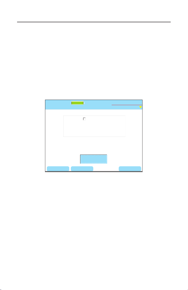
Test-Um NT955 Series
IP Address
Untitled1.job
2005 Aug 25
10:53:01
DNS
For manual IP address, uncheck DHCP. Netmask is count of 1 bits
GW/RTR
My IP
DHCP
192.168.1.200 / 24
Configure
IP Parameters
Test-Um Inc.
validator
DELETE TARGETSBACKSPC
My IP: 192.168.1.000
Netmask (CIDR): 000.000.000.0 (24)
Gateway/Router (GW/RTR): None
Domain Name Server (DNS): None
100%
ValidatorTM Network Tests
For manual IP addresses, uncheck the DHCP mode box by pressing
the up and down arrow keys to highlight the DHCP box and press
Select to deselect DHCP mode. Use the arrow keys to highlight the My
IP, Gateway Router (GWRTR) and Domain Name Server. Edit these
elds as necessary using the keypad, Backspace (F1) and Delete (F2)
soft keys. Press Accept to conrm your current selection and move to
the next eld. The Netmask is entered next to My IP as a count of ones
starting from the left (FFF0 = 24, FFE0 = 24, etc.). Press the down arrow
to Select the box titled Congure IP Parameters and initiate the operation
to verify that the MY IP address entered is not in use already.
Figure 6.9 Manual Mode IP Addresses
80
Page 82
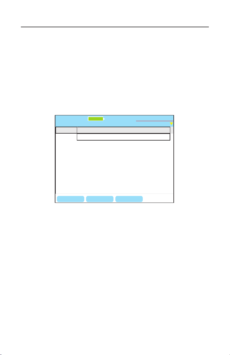
Test-Um NT955 Series
BACKSPC
Type Target
HOST/IP 1
HOST/IP 2
HOST/IP 3
HOST/IP 4
www.Test-Um.com
Manual Ping Targets
Untitled1.job
Test-Um Inc.
validator
DELETE
WWW..COM
100%
2005 Aug 25
10:53:01
ValidatorTM Network Tests
The Ping Targets must also be set manually. To change the IP targets,
press the Targets soft key (F4) and edit these elds as necessary using
the keypad, Backspace (F1) and Delete (F2) soft keys. The www.com
soft key (F3) is used as a shortcut to add the common “www.” prex and
the “.com” sufx to an entered name. Pressing the F3 soft key would
change “Test-Um” to “www.Test-Um.com”. When entering addresses,
the * button is a shortcut for the period (.) punctuation mark needed
to enter dotted-quad or URL addresses. Press Quit to return to the
previous screen, either IP Address or Ping Tool.
Figure 6.10 Manual Ping Targets
81
Page 83
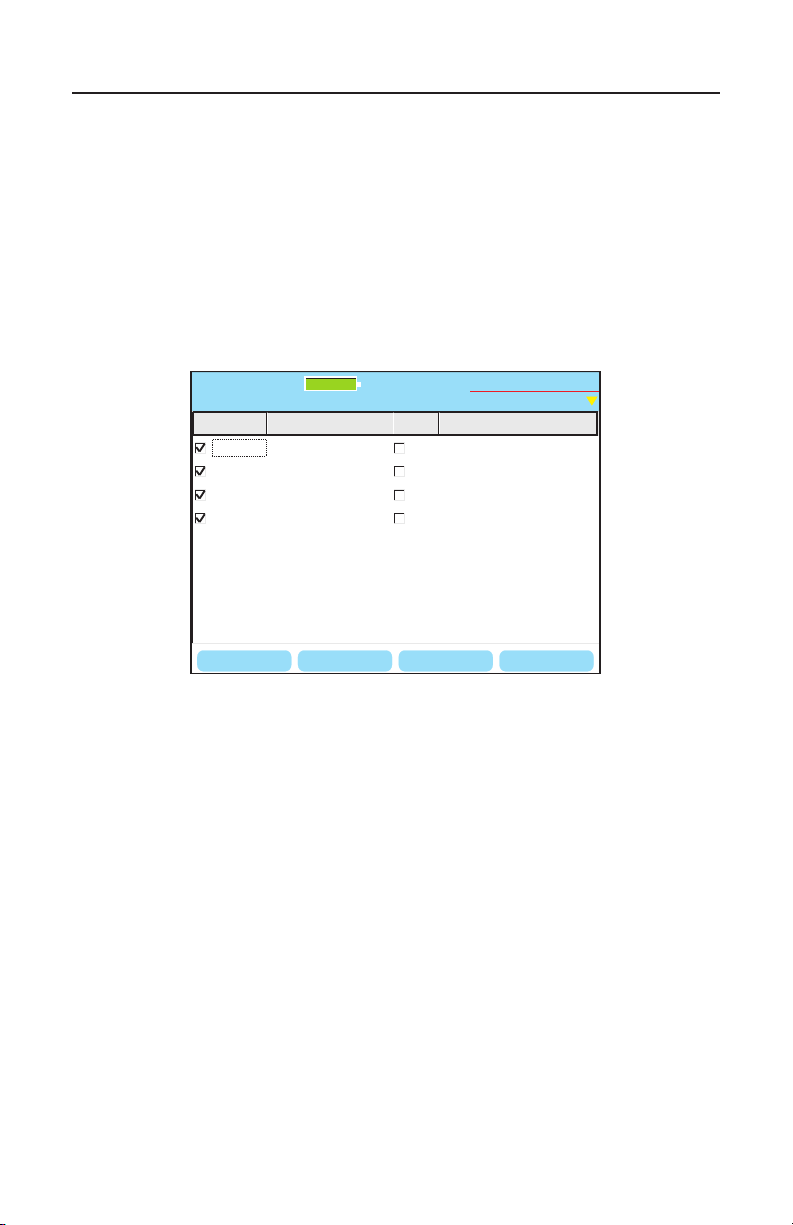
Test-Um NT955 Series
BACKSPC
PING Target Size Received/Sent ms
HOST/IP
GW/RTR 192.168.1.1
DNS 192.168.1.100
HOST/IP www.yahoo.com
www.Test-Um.com Long
Long
Long
Long
Ping Tool
Untitled1.job
Test-Um Inc.
validator
DELETE
100%
2005 Aug 25
10:53:01
TARGETSPING
ValidatorTM Network Tests
The Ping Tool soft key (F3) only shows on the IP address screen once
valid DHCP information or manual IP addresses are congured. All
the IP addresses that are currently setup to be pinged are displayed on
entry. Uncheck the box next to any addresses you do not want to ping.
The Host/IP address can be edited directly on this screen (the default
URL is www.test.um.com) and the Targets soft key (F4) and subsequent
screen is used to edit the four other user dened targets. Press the
Ping soft key to start the ping operation of up to seven IP addresses
simultaneously. Press quit to stop.
Figure 6.11 IP Addresses Setup to be Pinged
82
Page 84
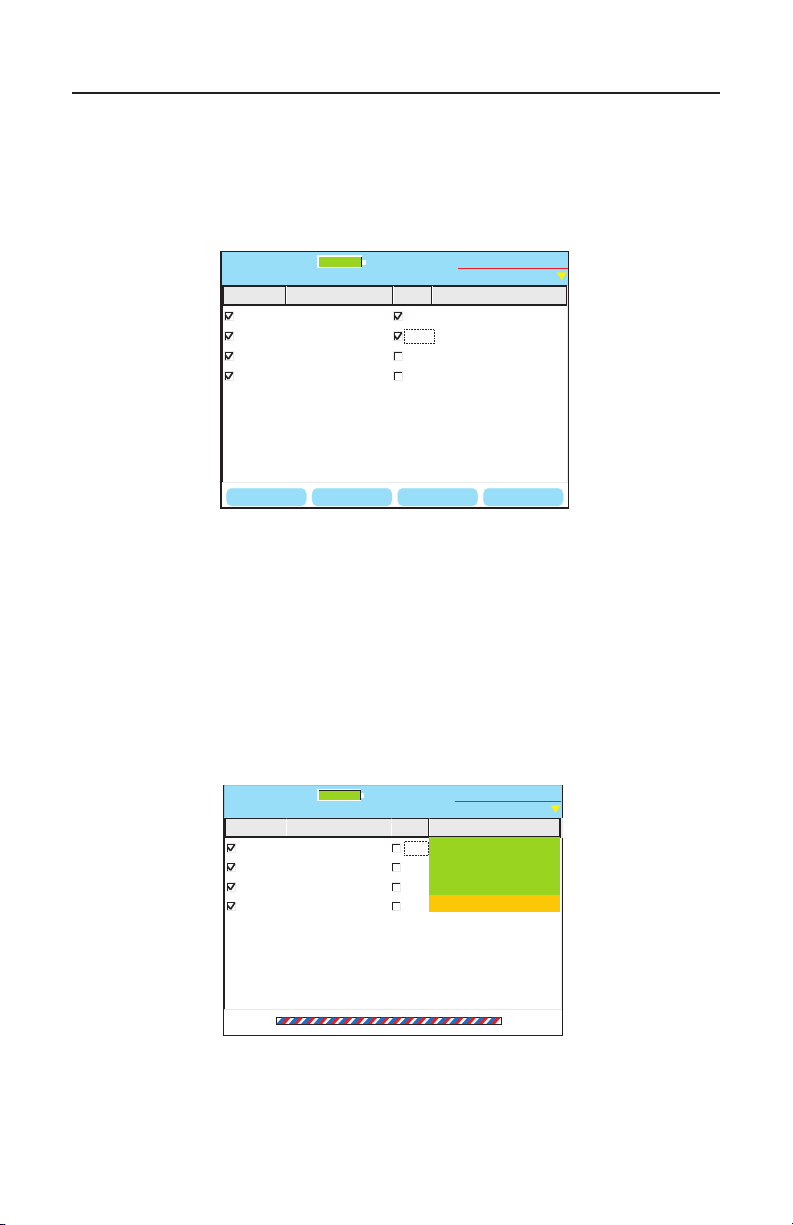
Test-Um NT955 Series
BACKSPC
PING Target Size Received/Sent ms
HOST/IP
GW/RTR 192.168.1.1
DNS 192.168.1.100
HOST/IP www.yahoo.com
www.Test-Um.com Long
Long
Long
Long
Ping Tool
Untitled1.job
Test-Um Inc.
validator
DELETE
100%
2005 Aug 25
10:53:01
TARGETSPING
PING Target Size Received/Sent ms
HOST/IP
GW/RTR 192.168.1.1
DNS 192.168.1.100
HOST/IP www.yahoo.com
www.Test-Um.com Long
Long
Long
Long
Ping Tool
Untitled1.job
Test-Um Inc.
validator
100%
2005 Aug 25
10:53:01
62/90 1.5
62/90 1.1
xxx
62/90 1.7
ValidatorTM Network Tests
You can increase the length of the data packet used to ping by
highlighting the target IP Address and using the right arrow key to
highlight the word Long. Press Select to toggle the size of the data
packet between normal and long.
6.12 Adjusting the Length of the Ping Packet
Press the Ping soft key to start the ping operation of up to seven IP
addresses simultaneously. Press quit to stop. The Validator-NT will issue
a DHCP release request to the DHCP server when in DHCP mode. This
is preferable to simply disconnecting the cable because the IP address
pinged will not be available for assignment to any other device.
Figure 6.13 Ping Test Result
83
Page 85
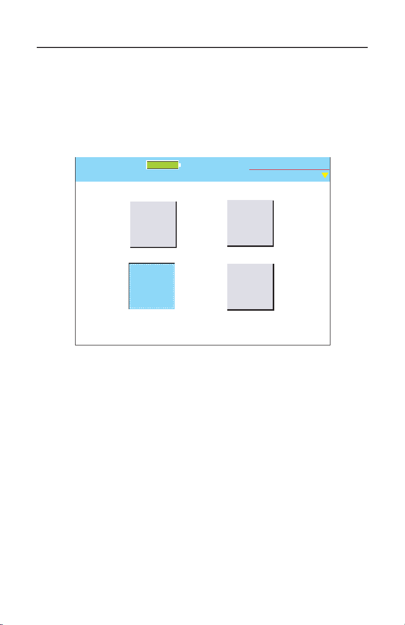
Test-Um NT955 Series
Untitled1.job
Cisco
Discovery
Protocol
Test-Um Inc.
validator
100%
Hub
Flash
Ping Test
Port
Discovery
Network Tests
2006 Jul 05
10:53:01
6.3 Cisco Delivery Protocol
This feature detects Cisco Delivery Protocol (CDP) messages broadcast
by Cisco bridges and routers over the network to inform each other of
their existence. The content of the CDP message contains addresses
that SNMP messages can be sent to.
6.14 Network Test/Cisco Discovery Protocol
84
Page 86
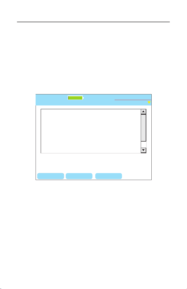
Test-Um NT955 Series
Port (Our Port): eth0
Device-ID: cisco_3524
Device addresses:
IP address: 192.168.1.252
Holdtime: 179 sec
Capabilities: Transparent_Bridge Switch
Version:
Cisco Internetwork Operating System Software
IOS ™ C3500XL Software (C3500XL-C3H2S-M),
Version 12.05(5)XU, RELEASE SOFTWARE (fc1)
Copyright (c) 1986-3000 by cisco Systems Inc.
CDP Display Screen
Untitled1.job
BACKSPCCLEAR START
Test-Um Inc.
validator
100%
2006 Jul 05
10:53:01
STOP
Reading CDP Package from Network
To view Cisco Delivery Protocol broadcast messages
1. From the Start Menu, select Network Tests. Select Cisco
Delivery Protocol.
2. Use a patch cable to connect the Validator-NT main unit to the
network or device port to be monitored for CDP.
3. CDP information automatically displays and a message “Reading
CDP packets from network” appears on your screen below the
CDP message.
6.15 Reading CDP Package
85
Page 87
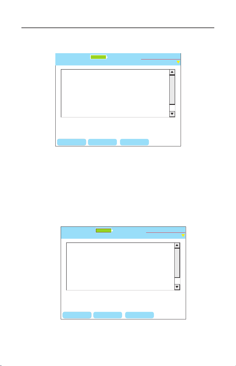
Test-Um NT955 Series
CDP Display Screen
Untitled1.job
BACKSPCCLEAR START
Test-Um Inc.
validator
100%
2006 Jul 05
10:53:01
STOP
Reading CDP packets from network.
Port (Our Port): eth0
Device-ID: cisco_3524
Device addresses:
IP address: 192.168.1.252
Holdtime: 179 sec
Capabilities: Transparent_Bridge Switch
Version:
Cisco Internetwork Operating System Software
IOS ™ C3500XL Software (C3500XL-C3H2S-M),
Version 12.05(5)XU, RELEASE SOFTWARE (fc1)
Copyright (c) 1986-3000 by cisco Systems Inc.
CDP Display Screen
Untitled1.job
BACKSPCCLEAR START
Test-Um Inc.
validator
100%
2006 Jul 05
10:53:01
SAVE TYPE
Ignoring CDP packets from network.
4. To clear the current broadcast, press the Clear soft key (F1).
The screen goes blank.
6.16 Selecting Clear for CDP Display Screen
5. To start a new broadcast, press the Start soft key (F2). The
message “Reading CDP packets from network” appears on your
screen below the CDP message.
6. To stop the current broadcast, press the Stop soft key (F3). A
message “Ignoring CDP packets from network” appears on the
screen below the CDP message.
6.17 Selecting Stop for CDP Display Screen
86
Page 88
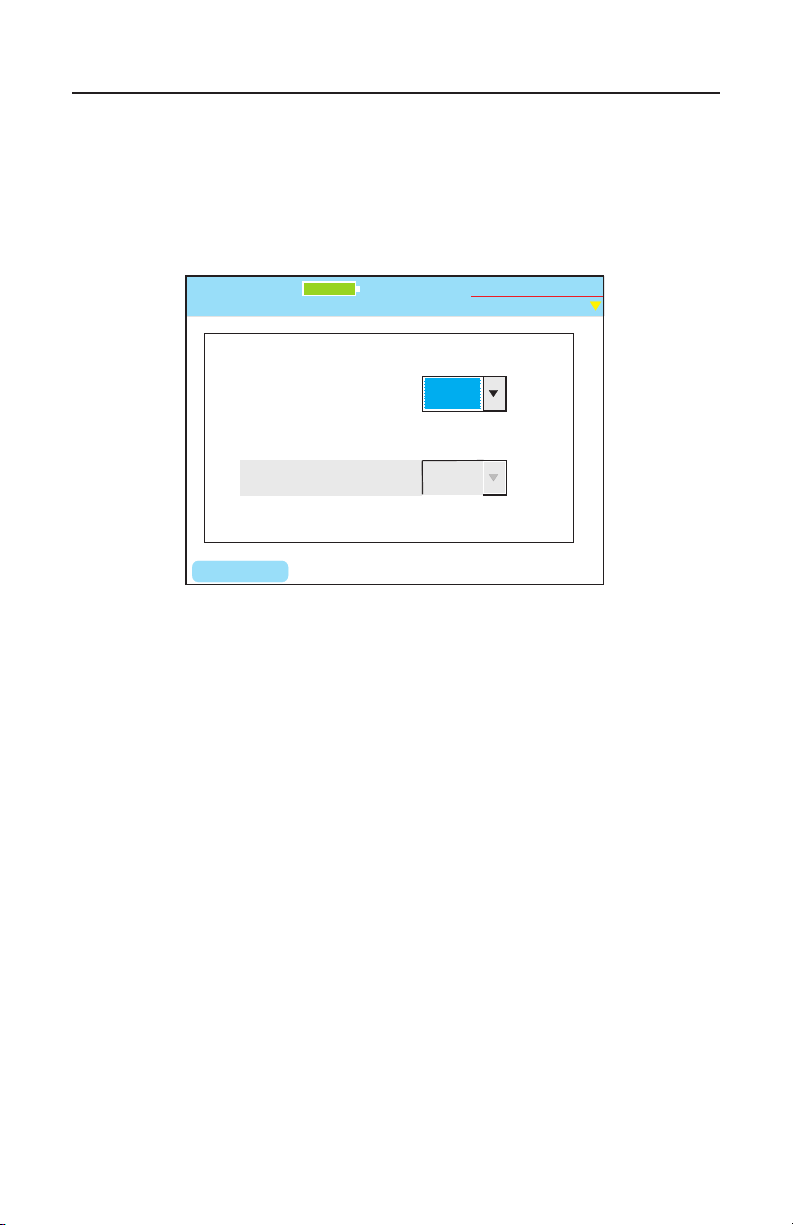
Test-Um NT955 Series
Select Rate:
Hub Flash
Untitled1.job
Auto
NIC Wiring:
Flash Any, Auto
Any
FLASH
Test-Um Inc.
validator
100%
2005 Aug 25
10:53:01
O
ValidatorTM Network Tests
6.4. Hub Flash
Hub ash sends an intermittent link signal to ash the link status light on
Ethernet equipment. You can select a specic data rate or Any if you
wish to have the hub and the Validator-NT auto negotiate the speed.
6.18 Hub Flash in progress
87
Page 89

Test-Um NT955 Series
6.5. Step by Step Instructions for Performing Network Tests
1. From the Start Menu, select Network Tests. Choose Port
Discovery, Ping Test or Hub Flash.
Warning! Network Test Results will NOT be saved
2. Use a patch cable to connect the Validator-NT main unit to the
jack or network device to be tested.
Port Discovery
1. From the Start menu, navigate to Network Tests using the arrow
keys which move from left to right on each row.
2. Using the RJ45 port, connect the appropriate cable assembly
from the Validator-NT main unit to one end of the cable or jack
and the remote unit to the opposite end of the cable or jack to be
identied.
3. Select Port Discovery to start a test sequence. Press TEST to
retest once the Port Discovery screen is displayed.
ValidatorTM Network Tests
4. If neither voltage nor Ethernet is detected, the Validator-NT
searches for its remote to run a cable test. If a remote is not
found, a one-ended test for shorts and split pairs is run and the
results are reported.
88
Page 90

Test-Um NT955 Series
Ping Test
1. Select Ping Test.
2. Press Select to begin DHCP request (DHCP box checked)
or to Congure IP addresses in manual address mode (box
unchecked). In manual address mode, be sure the displayed
addresses are appropriate for the network being tested. If not,
use the keypad, Backspace (F1) and Delete (F2) soft keys to edit
My IP Address, Gateway Router (GWRTR) and Domain Name
Server (DNS).
3. To change the targets, press the Targets soft key (F4) to
enter the Manual Ping Targets screen and use the keyboard,
Backspace (F1) and Delete (F2) soft keys to edit the target IP
addresses. When entering addresses, the * button is a shortcut
for the period (.) punctuation mark. Press escape when done to
return to the previous screen.
4. Press the Ping Tool soft key to begin pinging the entries with the
box checked.
5. Press Quit to return to the IP Address screen.
ValidatorTM Network Tests
Cisco Delivery Protocol
1. Select Cisco Delivery Protocol.
2. Using the RJ45 port, connect the appropriate cable assembly
from the Validator-NT main unit to one end of the cable or jack
and the remote unit to the opposite end of the cable or jack to be
identied.
3. Press Select to display a message “Reading CDP packets from
network” appears on your screen below the CDP message.
89
Page 91

Test-Um NT955 Series
Hub Flash
1. Select Hub Flash.
2. From the drop down menu, select a specic data rate or Any if
you wish to have the hub and the Validator-NT auto negotiate the
speed. Press Accept.
3. In 10Mb or 100 Mb mode, the Validator-NT can be set to emulate
a NIC, a HUB or an Auto mode (auto MDI/MDIX) device using
the drop down menu. If plugging into a hub, the Validator-NT
must be set to NIC or Auto modes. The Auto mode can be used
most of the time, but it may be necessary to select Hub or NIC
mode when connecting to a network device that can “sleep” such
as a laptop computer to wake it up. Or if the device to be ashed
is slow to negotiate in the auto mode.
4. Press Flash (F1) soft key to begin.
ValidatorTM Network Tests
90
Page 92

Test-Um NT955 Series
ValidatorTM Uploading/Downloading Jobs
7. Uploading/Downloading Jobs
7.1. Uploading the Cable Test Schedule to the Validator-NT
Open the My Documents folder on your desktop. Right click the Plan-
Um job you want to transfer, and select Copy.
Power the Validator on. Open the My Computer folder on your desktop.
Plug the USB cord into the USB port on your PC and into the ValidatorNT (Figure 6.1). As the connection is made, the drive the Validator is
mapped to (usually Local Disk E:) appears on your desktop and the
message “USB – File I/O Mode” appears in red on the Validator.
Right click the drive the Validator is connected to and select Paste to
transfer the job le to the compact ash card on the Validator.
Do not remove the USB cable after this procedure; instead follow the
instructions below to safely remove the USB cable
On your system tray (lower right side on your desk top), click the USB
icon to safely remove hardware or Stop Mass Storage Device.
This completes the upload operation. Remove the USB cable from the
Validator. When you remove the USB cable, the power automatically
turns off on the Validator.
Power the unit on, select Job Manager, and open the job to begin testing.
After you complete the testing and verication of the cables with the
Validator, you will download the test results to Plan-Um, populating the
Length and Results columns on the Cable Test schedule.
91
Page 93
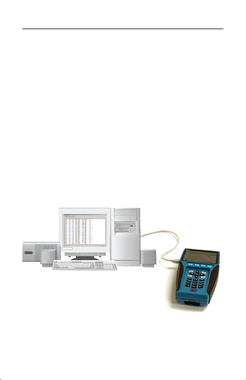
Test-Um NT955 Series
7.2. Downloading Test Results from Validator-NT to Plan-Um
Open the My Computer folder on your desktop. Power the Validator-
NT on. Plug the USB cord into the USB port on your PC and into the
Validator-NT (Figure 7.1). As the connection is made, the drive the
Validator is mapped to (usually Local Disk E:) appears on your desktop
and the message “USB – File I/O Mode” appears in red on the Validator.
Right click the drive the Validator is connected to and select Copy. Open
the My Documents folder on your desktop, right click, and select Paste.
Select Yes to replace the previous le with one you just downloaded that
contains the test results.
Do not remove the USB cable after this procedure; instead follow
the instructions below to safely remove the USB cable. On your
system tray (lower right side on your desk top), click the USB icon to
safely remove hardware or Stop Mass Storage Device.
Open Plan-Um and open the selected job le to view the populated
Length and Results columns of the Cable Test Schedule.
ValidatorTM Uploading/Downloading Jobs
Figure 7.1 Diagram of Validator-NT Connected to PC
92
Page 94
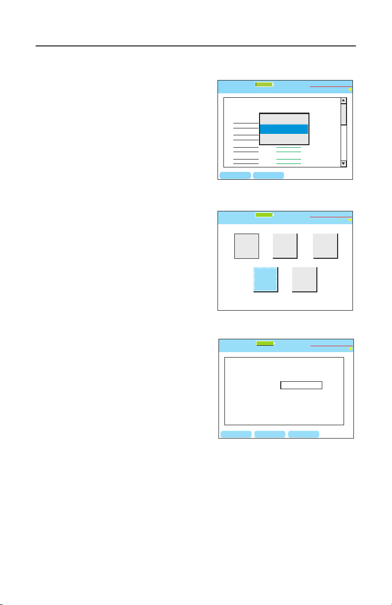
Test-Um NT955 Series
Test Results
Untitled1.job
Expected Results
1 1
2 2
3 3
6 6
4 4
5 5
7 7
8 8
Cable001 Pass
1 1
2 2
3 3
6 6
4 4
5 5
7 7
8 8
Test Time: 10/11/2004 10:53 A.M
4369ft
4369ft
Home
Save Job
CF Shutdown
Test-Um Inc.
validator
BACKSPC
PG UP PG DOWN
CAT5E
1 Gbit/s
100%
2005 Aug 25
10:53:01
Export Tut
Open
New
Job Utilities
Untitled1.job
Save As
Save
Test-Um Inc.
validator
100%
2005 Aug 25
10:53:01
BACKSPC
Current File:
New File:
Save As
Untitled1.job
Untitled1.job
DELETE OK
Test-Um Inc.
validator
100%
2005 Aug 25
10:53:01
ValidatorTM Archiving /Saving Test Results
8. Archiving/Saving Test Results
To save, press Menu. Use the Up
Arrow key to highlight Save Job and
press Select to save your Test Results
to the ash memory card. (Figure 8.1)
Another method for saving a job is
to select the Job Utilities menu from
the Current Job screen and press the
Save or Save As option. (Figure 8.1)
“Save as” will save your job as a
new le name. Enter a name into the
highlighted box next to New File using
your alphanumeric keys. (Figure 8.1)
Test results Auto Save after every cable test is performed. However, Job
Information must be saved manually.
Download Test Results to a pc/laptop. Stored job information is used to
generate an End of Job Report. Refer to the archived job for additional
moves, adds, and changes.
Figure 8.1 Options for Saving Jobs
93
Page 95
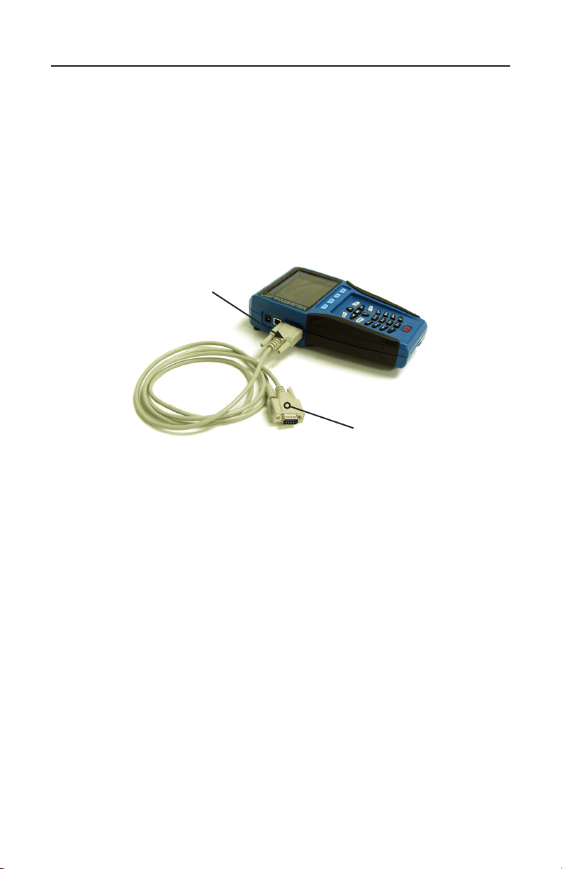
Test-Um NT955 Series
ValidatorTM Printing Test Results
9. Printing Test Results
The most efcient method to print job reports is to download test results
to a pc/laptop. See Uploading/downloading Jobs.
Future upgrades may permit the user to print Test Results directly from
the Validator-NT to a serial port printer using a D-Sub 9 pin Male to
Female cable assembly. (Figure 9.1)
Validator-NT Serial Port
D-Sub 9 pin Male
to Female Cable
Assembly
Figure 9.1 Serial Port Cable Connection to Validator-NT
94
Page 96

Test-Um NT955 Series
ValidatorTM Application Notes
10. Application Notes for Typical Field Use
10.1. New Job, New Cable Installations
1. A Layout using the Plan-Um software will be created conforming
to the customers’ facility or residence and a job id created.
2. Cables will be chosen and run between agreed upon ports and a
Comm. Panel or Patch Panel.
3. Check Cable Test Schedule against the Layout to make sure all
ports are connected correctly.
4. The Job File from the Plan-Um software will be uploaded to
the Validator-NT Main unit. The Job File can then be accessed
through the Job Manager on the Main Menu Screen of the
Validator-NT.
5. The Cable Test Schedule can be sorted so that all CAT 5E
cables are listed rst or all CAT 5 etc. This groups the types of
cables for quicker testing at the Comm. or Patch Panel.
6. Once all tests are done, upload the nished Cable Test Schedule
to the laptop or PC and print this as an End of Job report
showing all the cable runs and PASS/FAIL results. This should
be attached to a copy of the customer layout for comparison and
nal checking prior to billing.
10.2. New Job, Previously Installed Cables
1. Create a layout using the Plan-Um software re-creating the
customers’ cabling system using port and cable icons in PlanUm.
2. Name the job and upload it to Validator-NT for testing
3. Print out the nished Cable Test Schedule as an End of Job
report for the customer to see what was tested and results.
95
Page 97
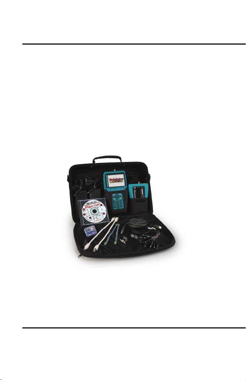
Test-Um Inc.
The Intelligent Test Solutions Company
808 Calle Plano
Camarillo, CA 93012
(805) 383-1500 / FAX (805) 383-1595
www.Test-Um.com
TU9862-1 (REV B-07/06)
 Loading...