

Page 1
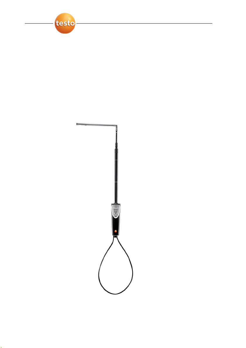
Thermal air flow measuring head and humidity probe
Application information
Page 2

2
Page 3
Pos: 1 /TD/Kurzanleitungen/testo 480/Thermisc he Strömungs-Messsond e 0635 1543 @ 9\mod_130935631 3939_79.doc @ 81186 @ 5555555 @ 1
Application
The thermal air flow measuring head and humidity probe 0635
1543 is suitable in conjunction with testo 480 for flow and humidity
measurements in ventilation channels and at ceiling/wall outlets.
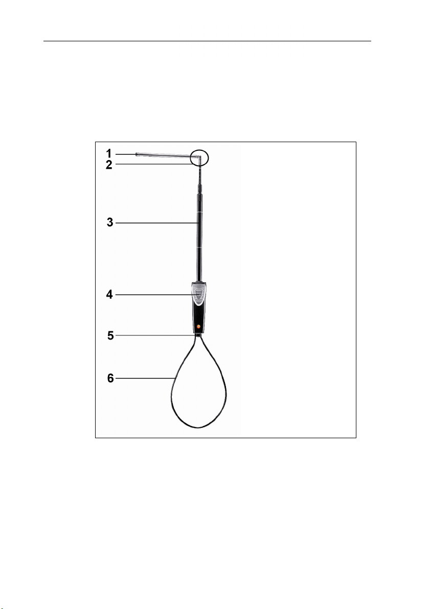
Overview
1 Flow probe
2 Joint for 90° bend
3 Telescope with scale
4 Handle with integrated measurement button
5 Connection for plug-in head cable (art. no. 0430 0100)
6 Telescope cable
3
Page 4

Technical data
Feature Values
Measurement range 0 to +20.00 m/s
-20 to 70 °C
0 to 100%RH (non-condensing)
Accuracy: (at 22°C) ±
1
1 digit
±(0.03 m/s, + 4% of meas. val.)
±0.5°C
±(1.8%RH + 0.7% of meas. val.)
±0.03%RH/K (based on 25°C)
At lower flow velocities, higher
measurement inaccuracies can
occur in temperature and humidity
measurement!
Adjustment conditions
Adjustment in free jet Ø 350 mm, reference
pressure 1013 hPa, based on testo
reference Laser Doppler Anemometer
(LDA)
Operating
0 to +40 °C
temperature, handle
The digital probe allows measurement values to be
processed directly in the probe. This technology eliminates
instrument measurement uncertainty.
For calibration, the probe alone (without the hand
instrument) can be sent away.
Calculating the determined calibration data in the probe
generates a zero-error display.
1
The measurement uncertainty for the relative humidity was calculated
according to GUM and includes hysteresis, dispersion, linearity, uncertainties of
adjustment and test site, and display resolution. This does not include the
uncertainty values of long-term stability and drift in the case of long-term high
humidity measurement.
4
Page 5

Preparing for measurement
> Pull out the telescope to the required length. The individual
joints of the telescope click into place.
Measuring flows
For velocity measurements with a known direction of flow, the
arrow mark on the probe head must point in the direction of flow.
The correct measurement value is determined by rotating the probe
slightly in both directions until the maximum value is displayed.
Identifying unknown flow directions
Procedure for measurements in channels with an unknown flow
direction.
1. Remove protection cap from the probe head.
2. Place the probe in the flow.
3. Match up the probe axis with the assumed flow axis.
4. Read the measurement value.
5. Rotate the probe 180° and read off the measurement value
again.
- The higher measurement value determines the flow direction.
Procedure when measuring in flows with an unknown flow axis.
> Rotate the probe 360°. Keep a constant eye on the
measurement value.
5
Page 6

=== Ende der Liste für Textmarke Inhalt ===
- The maximum value determines the flow direction here, which
can then be read via marking.
After the measurement
> Pull the protection cap over the probe head.
> Slide the telescope back, starting with the joints closest to the
handle. Make sure that there are no kinks in the telescope
cable.
6
Page 7

Page 8

0970 0479 en 02
 Loading...