

Page 1
5 Commonwealth Ave
Woburn, MA 01801
Phone 781-665-1400
Toll Free 1-800-517-8431
Visit us at www.TestEquipmentDepot.com
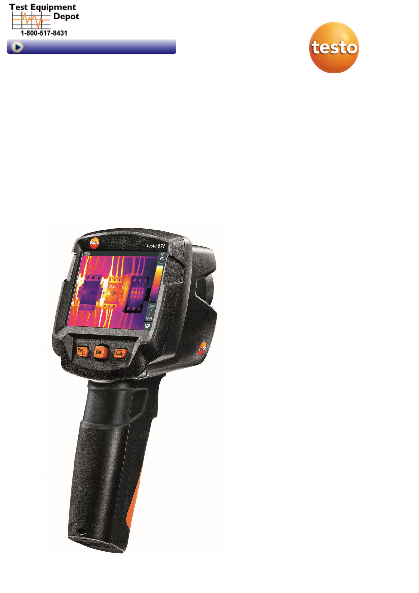
testo 871 - Thermal Imager
Instruction manual
Page 2

Contents
Contents
1 Safety and disposal .............................................................................. 3
1.1
About this document .............................................................................. 3
1.2
Security .................................................................................................. 3
1.3
Disposal ................................................................................................. 5
2
Technical data ..................................................................................... 5
2.1
Bluetooth module ................................................................................... 5
2.2
General technical data ........................................................................... 5
3
Description of the instrument ............................................................... 9
3.1
Use ......................................................................................................... 9
3.1
Instrument / operating elements overview ............................................. 9
3.1
Displays overview................................................................................. 10
3.2 Power supply ....................................................................................... 11
4
Operation ........................................................................................... 12
4.1
Commissioning .................................................................................... 12
4.2
Switching instrument on and off .......................................................... 12
4.3
Getting to know the menu .................................................................... 13
4.4
Quick select button .............................................................................. 14
5 WLAN connection - using the App ..................................................... 16
5.1
Activating/disabling the connection ..................................................... 16
5.2
Using the App ...................................................................................... 17
5.2.1 Establishing a connection ...................................................... 17
5.2.2 Select display ........................................................................ 17
6
Bluetooth
7
Performing the measurement ............................................................. 19
7.1 Saving an image ................................................................................... 20
7.2
7.3
7.4
7.5
7.6
®
connection ....................................................................... 18
Setting measuring functions ................................................................ 21
Image gallery ........................................................................................ 22
Setting the scale .................................................................................. 25
Setting emissivity and reflected temperature ....................................... 27
7.5.1 Selecting the emissivity ......................................................... 28
7.5.2 Customizing the emissivity .................................................... 29
7.5.3 Setting the RTC ..................................................................... 29
7.5.4 Setting ε-Assist...................................................................... 29
Selecting the colour palette ................................................................. 30
Page 3

Contents
7.7 Image type ........................................................................................... 30
7.8
Activating humidity, solar or electrical mode ....................................... 30
7.9
Activating the differential temperature ................................................. 31
7.10
Configuration ....................................................................................... 32
7.10.1 Settings ................................................................................. 32
7.10.2 SuperResolution ................................................................... 33
7.10.3 Save JPEG function ..............................................................
7.10.4 Connectivity .......................................................................... 34
7.10.5 Ambient conditions ............................................................... 34
7.10.6 Info ........................................................................................ 35
7.10.7 Fullscreen
7.10.8 Reset options ........................................................................ 35
8
Maintenance ...................................................................................... 37
8.1
Charging the rechargeable battery ...................................................... 37
8.2
Changing the rechargeable battery ..................................................... 37
8.3
Cleaning the instrument ....................................................................... 39
8.4
Firmware Update ................................................................................. 40
8.4.1 Update with IRSoft ................................................................ 40
8.4.1.1 Prepare the Camera ............................................. 40
8.4.1.2 Execute Updat
8.4.2 Update with the camera ........................................................
8.4.2.1 Prepare
8.4.2.2 Execute Updat
9
Tips and assistance ........................................................................... 42
9.1 Questions and answers ....................................................................... 42
9.2
Accessories and spare parts ............................................................... 42
10
Authorisations and certification .......................................................... 43
mode
................................................................... 35
e .................................................... 40
camera ................................................... 41
e .................................................... 41
33
41
Page 4

1 Safety and disposal
1 Safety and disposal
1.1 About this document
∑ The instruction manual is an integral part of the instrument.
∑ Keep this documentation to hand so that you can refer to it when
necessary.
∑ Always use the complete original instruction manual.
∑ Please read this instruction manual through carefully and familiarize yourself
with the product before putting it to use.
∑ Hand this instruction manual on to any subsequent users of the product.
∑ Pay particular attention to the safety instructions and warning advice in
order to prevent injury and damage to the product.
1.2 Security
General safety instructions
∑ Only operate the product properly, for its intended purpose, and within the
parameters specified in the technical data.
∑ Do not apply any force.
∑ Do not operate the instrument if there are signs of damage on the housing,
mains unit or connected cables.
∑ Dangers may also arise from objects to be measured or the measuring
environment. Always comply with the locally valid safety regulations when
carrying out measurements.
∑ Do not store the product together with solvents.
∑ Do not use any desiccants.
∑ Only perform maintenance and repair work on this instrument that is
described in this documentation. Follow the prescribed steps exactly when
doing the work.
∑ Use only original spare parts from Testo.
∑ During operation, this instrument must not be pointed at the sun or other
intensive sources of radiation (e.g. objects with temperatures exceeding
650 °C). This can lead to serious damage to the detector. The manufacturer
does not provide any warranty for any such damage to the microbolometer
detector.
3
Page 5
1 Safety and disposal
Batteries
∑ Improper use of batteries may cause the batteries to be destroyed, or lead
to injury due to current surges, fire or escaping chemicals.
∑ Only use the batteries supplied in accordance with the instructions in the
instruction manual.
∑ Do not short-circuit the batteries.
∑ Do not take the batteries apart and do not modify them.
∑ Do not expose the batteries to heavy impacts, water, fire or temperatures in
excess of 60 °C.
∑ Do not store the batteries in the proximity of metal objects.
∑ In the event of contact with battery acid: rinse affected areas thoroughly
with water, and if necessary consult a doctor.
∑ Do not use any leaky or damaged batteries.
∑ Only charge the rechargeable battery in the instrument or in the
recommended charging station.
∑ Immediately stop the charging process if this is not completed in the given
time.
∑ Take the rechargeable battery out of the instrument immediately if it is not
functioning properly or if it shows signs of superheating. Rechargeable
battery may be hot!
∑ When not in use for a long period of time, take the rechargeable battery out
of the instrument to prevent exhaustive discharge.
Warnings
Always pay attention to any information denoted by the following warnings.
Implement the precautionary measures specified!
Display Explanation
WARNING
CAUTION
ATTENTION
Indicates possible serious injury.
Indicates possible minor injury.
Indicates possible damage to equipment.
4
Page 6
2 Technical data
1.3 Disposal
∑ Dispose of faulty rechargeable batteries and spent batteries in accordance
with the valid legal specifications.
∑ At the end of its useful life, deliver the product to the separate collection
point for electric and electronic devices (observe local regulations) or return
the product to Testo for disposal.
2 Technical data
2.1 Bluetooth module
The use of the wireless module is subject to the regulations and
stipulations of the respective country of use, and the module may only
be used in each case in countries for which a country certification has
been granted.
The user and every owner undertake to adhere to these regulations
and prerequisites for use, and acknowledge that the re-sale, export,
import, etc. in particular in, to or from countries without wireless
permits, is their responsibility.
2.2 General technical data
Infrared image output
Feature Values
Infrared resolution 240 x 180
Thermal sensitivity (NETD) 90 mK
Field of view (FOV) / min.
focusing distance
Geometric resolution (IFOV) 2.6 mrad
SuperResolution 480 x 360 pixels / 1.6 mrad
IR image refresh rate 9 Hz
Focus Fixed focus
Spectral range 7.5 - 14 μm
35° x 26° / <0.5 m
5
Page 7
2 Technical data
Visual image output
Feature Values
Image size / min. focusing
distance
Image presentation
Feature Values
Display 8.9 cm (3.5") TFT, QVGA (320 x 240 pixels)
Display options
Interface
Colour palettes 4 options:
Measurement
Min. 3.1 MP / 0.5 m
∑ Infrared image
∑ Real image
∑ WLAN
∑ Bluetooth
∑ USB 2.0 micro B
∑ Iron
∑ Rainbow HC
∑ Cold-hot
∑ Grey
Feature Values
Measuring range -30 to 650 °C
Accuracy
∑ -30 to -21 °C ± 3 °C
∑ -20 to +650 °C ± 2 °C / ± 2%
ɛ-Assist Automatic emission value and RTC detection
Emissivity/reflected
0.01 to 1/manual
temperature adjustment
6
Page 8
2 Technical data
Measurement functions
∑ Single point measurement
∑ Coldspot
∑ Hotspot
∑ Differential temperature
∑ ScaleAssist
∑ IFOV warner
∑ Surface moisture distribution
∑ Humidity measurement with testo 605i
humidity probe
∑ Solar mode (manual)
∑ Electrical mode (manual)
∑ Electrical measurement with testo 770
wireless clamp meter
Imager equipment
Feature Values
Digital camera Yes
Fullscreen mode Yes
File format .jpg
Video streaming
∑ USB
∑ WLAN via the App
Image storage
Feature Values
File format
∑ .jpg
∑ .bmt
∑ Option of exporting in
.bmt
.jpg
.png
.csv
.xls
Memory capacity Internal mass storage 2.8 GB,
> 2000 images (without SuperResolution)
7
Page 9
2 Technical data
Power supply
Feature Values
Battery type Li-Ion rechargeable battery 2500 mAh / 3.7 V
Operating time 4.0 h @ 20 °C
Charging option In instrument/in charging station (optional)
Charging time approx. 5 h via mains unit
approx. 8 h via a PC's USB interface
USB Interface 5V 1.0A
* means direct current
Ambient conditions
Feature Values
Operating temperature -15 to 50 °C
Storage temperature -30 to 60 °C
Humidity 20 - 80 %RH, not condensing
Physical features
Feature Values
Weight 510 g (including battery)
Dimensions 219 x 96 x 95 mm
Housing PC/ABS
Protection class (IEC 60529) IP 54
Vibration (IEC 60068-2-6) 2 G
Standards, tests
Feature Values
EMC 2014/30/EU
RED 2014/53/EU
You can f
ind the EU declaration of conformity on the Testo homepage
www.testo.com under the product-specific downloads.
8
Page 10
3 Description of the instrument
3 Description of the instrument
3.1 Use
The testo 871 is a handy, robust thermal imager. You can use it to undertake
the non-contact measurement and display of surface temperature distribution.
Areas of application
∑ Building inspection: Energy efficiency rating of buildings (heating,
ventilation, air-conditioning trade, building engineers, engineering firms,
experts)
∑ Production monitoring / quality assurance: monitoring of production
processes
∑ Preventive maintenance / servicing: Electrical and mechanical inspection of
systems and machines
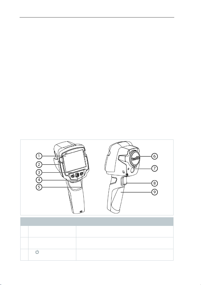
3.1 Instrument / operating elements
overview
Element Function
1 Display Displays infrared and real images, menus and
functions
2 Interface terminal Contains micro USB interface for power supply
and connection to the computer
3 - key
- Esc key
- Switch camera on and off
- Cancel action
9
Page 11
3 Description of the instrument
Element Function
4 - OK key
- Joystick
- Open menu, select function, confirm setting
- Navigate within the menu, highlight function,
select colour palette
5 Quick select button Opens the function assigned to the quick select
button; the icon for the selected function is
displayed bottom right
6 Infrared camera lens;
Takes infrared images; protects the lens
protective cap
7 Digital camera
Takes real images
(testo 871-2 only)
8 Trigger Saves the displayed image
9 Battery compartment Contains the rechargeable battery
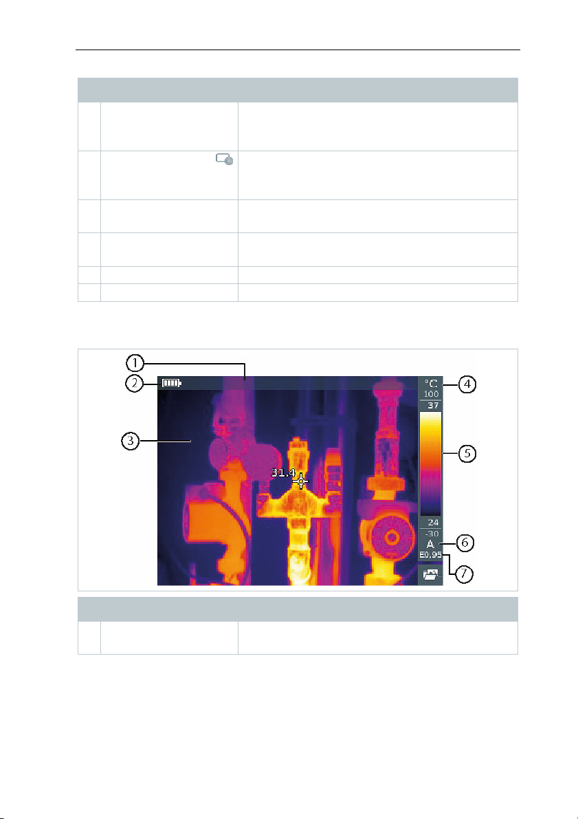
3.1 Displays overview
Element Function
1 Status bar In the status bar, values are displayed
depending on the setting.
10
Page 12
3 Description of the instrument
Element Function
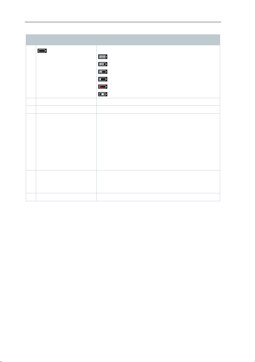
2 Battery capacity / charge status:
: Battery operation, capacity 75-100%
: Battery operation, capacity 50-75%
: Battery operation, capacity 25-50%
: Battery operation, capacity 10-25%
: Battery operation, capacity 0-10%
: Mains operation, battery is charging
3 Image display IR image or real image display
4 °C or °F Unit set for reading and scale displays
5 Scale - Temperature unit
- Grey characters: measuring range
- White characters: temperature margin of the
image displayed, showing the
minimum/maximum reading (with automatic
scale adjustment) or the selected
minimum/maximum display value (with
manual scale adjustment)
6 A, M or S A - automatic scale adjustment
M - manual scale adjustment
S - ScaleAssist is enabled
7 E ... Emissivity set
3.2 Power supply
The power is supplied to the instrument via a replaceable rechargeable battery
or the mains unit provided (battery must be inserted).
With an attached mains unit, power is supplied automatically via the mains unit
and the rechargeable battery is charged (only at ambient temperatures from 0
to 40°C).
If the instrument is switched off when connected to a PC via the USB interface,
the rechargeable battery is charged via the USB interface.
It is also possible to charge the battery using a charging station (accessory).
The instrument is equipped with a buffer battery to maintain the system data
during an interruption in the power supply (e.g. when the battery is changed).
11
Page 13
4 Operation
4 Operation
4.1 Commissioning
Please read the testo 871 1st steps commissioning instructions supplied
(0970 8652).
4.2 Switching instrument on and off
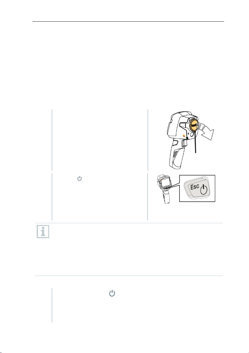
Switching on the camera
1
- Remove protective cap from the
lens.
2
- Press .
The camera starts.
The start screen appears on the
display.
The camera carries out automatic zeroing approx. every 60 seconds in
order to guarantee measuring accuracy. A "click" is heard when this
happens. The image freezes briefly when this occurs. Zeroing is
carried out more frequently during the camera warm-up period (takes
approx. 90 seconds).
During the warm-up period no measuring accuracy is guaranteed. The
image can already be used for indication purposes and saved.
Switching off the camera
1
- Press and hold down until the
progress bar is complete.
The display goes off.
12
Page 14
The camera is switched off.
4.3 Getting to know the menu
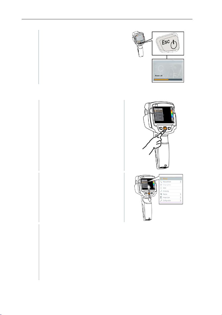
1 - Press OK to open the menu.
4 Operation
2 - Move the joystick down/up to
highlight a function (orange border).
3 - Press OK to select the function.
3.1 - Move the joystick to the right to open the submenu (marked with >).
- Return to the main menu:
o Move the joystick to the left or
o Move the joystick to the menu bar and press OK.
13
Page 15
4 Operation
4.4 Quick select button
The quick select button is another navigation option that you can use to call up
certain functions simply at the touch of a button.
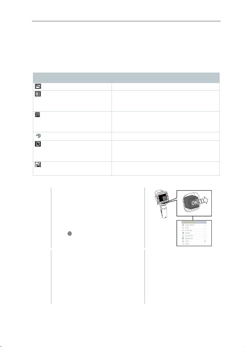
Quick select menu items
Menu item Function
Image gallery
Scale: This function is only
available if the Image type is
set to infrared)
Emissivity: This function is
only available if the Image type
is set to infrared)
Palette
Adjustment: This function is
only available if the Image type
is set to infrared)
Image type
Changing assignment
Opens an overview of saved images.
Set scale limits.
Set emissivity (E) and reflected temperature
(RTC).
Toggles the palette selection.
Carries out manual zeroing.
Alternately switches the image display
between infrared and real image.
1 - Move the joystick to the right.
The Configure key selection menu
appears.
The activated function is marked with
a dot ( ).
2 - Move the joystick up/down until the
orange box appears around the
required menu item.
- Press OK
The quick select button is assigned
to the selected menu item.
14
Page 16
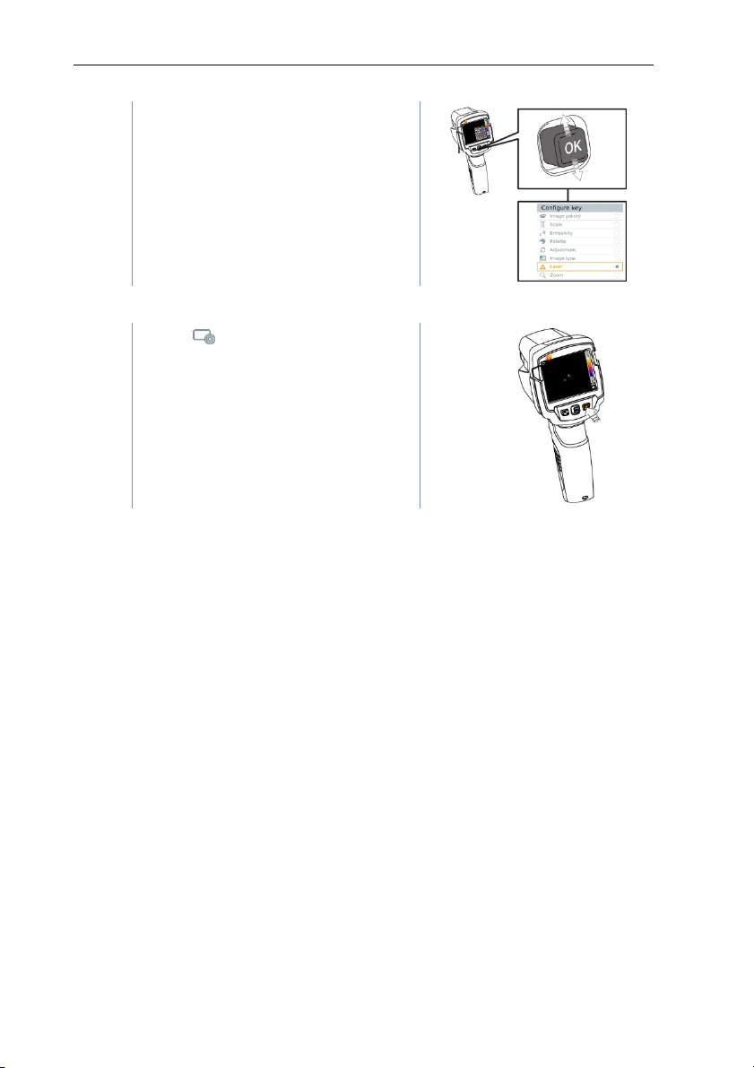
The icon for the selected function is
displayed bottom right.
Using the quick select button
1
- Press .
The function assigned to the quick
select button is carried out.
4 Operation
15
Page 17
5 WLAN connection - using the App
5 WLAN connection - using the App
5.1 Activating/disabling the connection
To connect via
Thermography App already installed on it.
You can get the App from the App Store for iOS devices or from the
Play Store for Android devices.
Compatibility:
Requires iOS 8.3 or later/Android 4.3 or later
1 - Open Menu.
2 - Move the joystick down and select Configuration.
- Press OK or move the joystick to the right.
3 - Move the joystick down and select Connectivity.
- Press OK or move the joystick to the right.
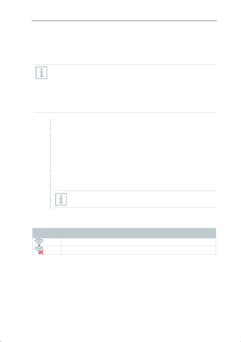
4 - Select WLAN and press OK to activate (a tick appears when WLAN
is activated).
Explanation of WL
Icon Function
App is connected
No connection
WLAN, you need a tablet or smartphone with the Testo
While WLAN is activated, the
accessed.
AN icons
to the App
image gallery cannot be
16
Page 18

5 WLAN connection - using the App
5.2 Using the App
5.2.1 Establishing a connection
- WLAN is activated in the thermal imager.
1 - Smartphone/tablet -> Settings -> WLAN settings -> camera is
shown with serial number and can be selected.
2 - Press Connect.
The WLAN connection to the thermal imager is established.
5.2.2 Select display
Second display
- The thermal imager is connected via WLAN.
1 - Selection -> 2nd display
The display on the thermal imager is shown on your mobile end
Remote
device.
- The thermal imager is connected via WLAN.
1 - Selection -> Remote
The display on the thermal imager is shown on your mobile end
device. The thermal imager can be controlled and settings made via
the mobile terminal device.
Gallery
- The thermal imager is connected via WLAN.
1 - Selection -> Gallery
The saved images are displayed and can be managed.
17
Page 19
6 Bluetooth® connection
6 Bluetooth® connection
A connection between the thermal imager and the testo 605i humidity probe or
testo 770-3 clamp meter can be established via Bluetooth®.
®
Bluetooth
1 - Open Menu.
2 - Move the joystick down and select Configuration.
- Press OK or move the joystick to the right.
3 - Move the joystick down and select Connectivity.
- Press OK or move the joystick to the right.
4.0 required
4
- Select Bluetooth
Bluetooth
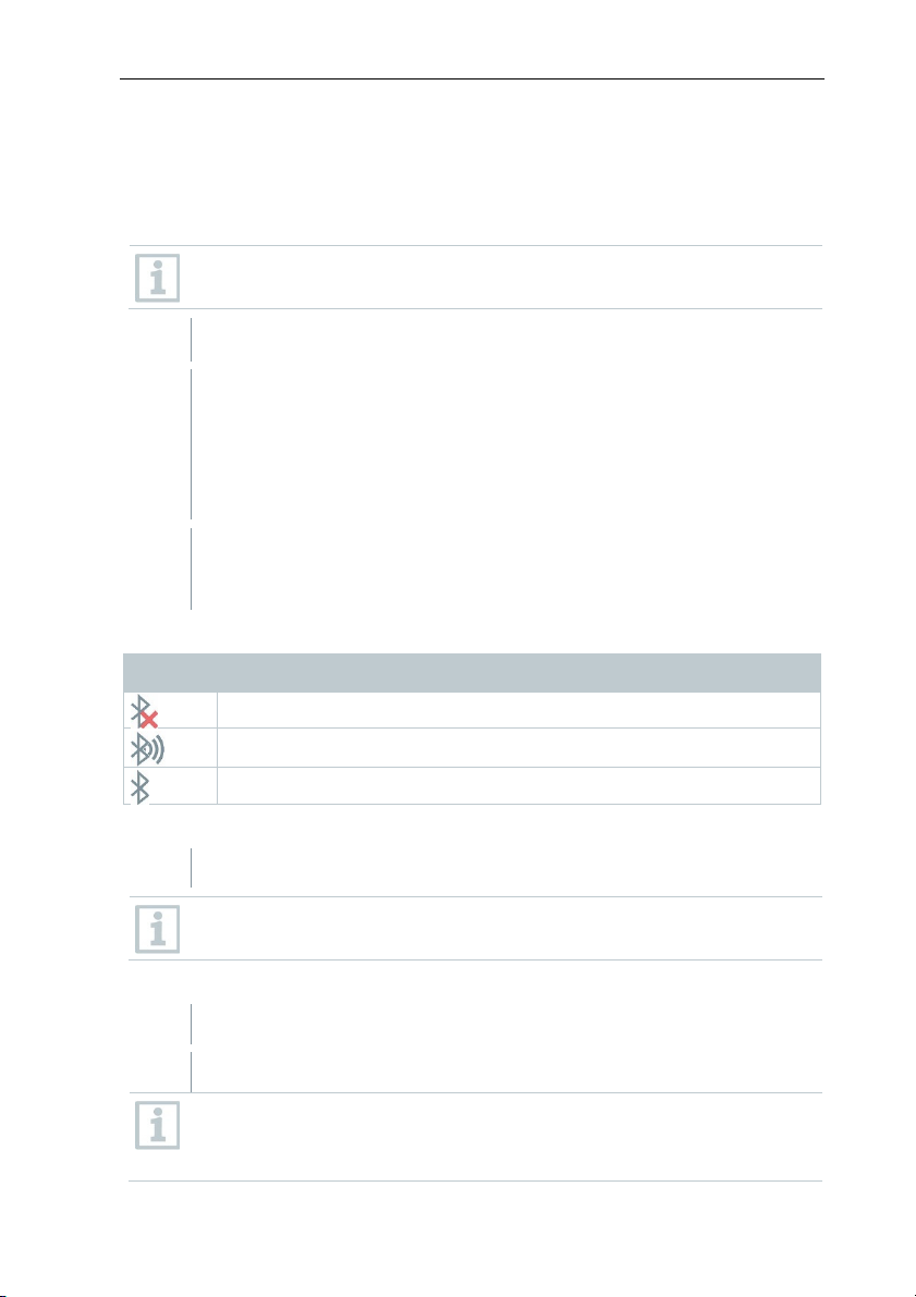
Explanation of Bluetooth® icons
Icon Function
No connection to the humidity probe
Searching for humidity probe.
Humidity probe readings are
When connected to the clamp meter
Clamp meter readings are displayed in the header.
Readings are o
the clamp meter.
When connected to the humidity probe
The thermal imager switches automatically to humidity measurement.
Humidity probe readings are displayed in the header.
If a WLAN con
transfer is continued. However, it is not possible to establish a new
connection to a humidity probe.
®
and press OK to activate (a tick appears when
®
is enabled).
being transmitted.
nly transferred if the current, voltage or power is set on
nection is enabled in addition, the Bluetooth data
18
Page 20
7 Performing the measurement
7 Performing the measurement
Factory settings
The instrument settings can be reset to the factory settings.
Time/date, country settings and counter are not reset.
1 - Menu -> Configuration -> Reset options.
2 - Select the Factory settings function.
Apply factory settings? is displayed.
3 - Press OK to apply factory settings.
2.1 - Press Esc to cancel the process.
Factory settings
The instrument settings can be reset to the factory settings.
Time/date, country settings and counter are not reset.
1 - Menu -> Configuration -> Reset options.
2 - Select the Factory settings function.
Apply factory settings? is displayed.
3 - Press OK to apply factory settings.
2.1 - Press Esc to cancel the process.
CAUTION
High thermal radiation (e.g. due to sun, fire, furnaces)
Detector may be damaged!
- Do not point the camera at objects with temperatures > 650 °C.
19
Page 21
7 Performing the measurement
Ideal framework conditions
∑ Building thermography, investigating the building shell:
Considerable temperature difference between inside and outside required
(ideal: ≥ 15 °C / ≥ 27 °F).
∑ Consistent weather conditions, no intensive sunlight, no precipitation, no
strong wind.
∑ To ensure maximum accuracy, the camera requires an adjustment time of
10 minutes after it is switched on.
Important camera settings
∑ Emissivity and reflected temperature must be set correctly in order to
precisely determine the temperature. Subsequent adjustment is possible via
the PC software, if required.
∑ When auto-scaling is activated, the colour scale is continuously adjusted to
the min./max. values of the current measurement image. This means that
the colour assigned to a specific temperature is changing constantly! To be
able to compare multiple images based on the assigned colour, scaling
must be set manually to fixed values, or must be subsequently adjusted to
uniform values using the PC software.
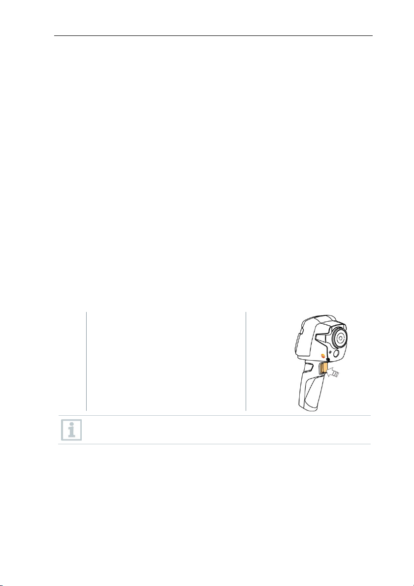
7.1 Saving an image
1 - Press Trigger.
The image is automatically saved.
Regardless of the image type set, an
infrared image is saved with an
attached real image.
If a higher resolution is required: in the menu under Configuration ->
select SuperResolution for four times as many readings.
20
Page 22

7 Performing the measurement
7.2 Setting measuring functions
1 - Open the Measurement submenu.
The submenu with measurement functions opens:
∑ Pixel mark:
o Single point measurement: the temperature measuring
point in the centre of the image is marked with white
crosshairs and the value is displayed.
o Coldspot, Hotspot: the lowest or highest temperature
measuring point is marked with blue or red crosshairs and
the value is displayed.
∑ Measurement range: choose between two temperature
ranges.
∑ Differential temperature: identifies the difference between two
temperatures.
∑ External measurement values: select Humidity, Current,
Voltage, Solar, Power, None.
∑ IFOV: the IFOV warner shows what can be measured
accurately from a specific distance.
2 - Move the joystick up/down to select the required function and
then press OK.
21
Page 23
7 Performing the measurement
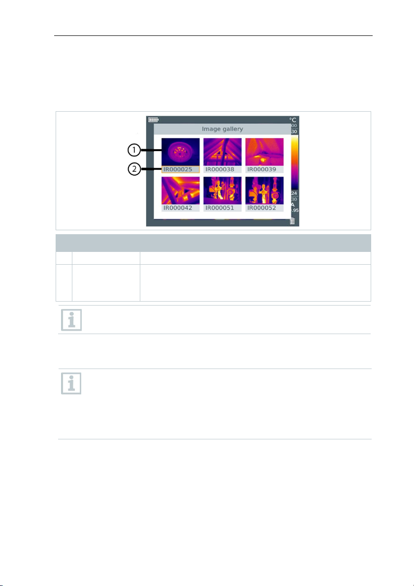
7.3 Image gallery
Saved images can be displayed, analysed or deleted.
File names
Designation Explanation
1 - Infrared image preview
2 IR
000000
SR
Infrared image with attached real image
Consecutive number
Images captured with SuperResolution
File names can be changed via the PC, e.g. in Windows Explorer.
Displaying a saved image
Saved images can be viewed and analyzed in the image gallery.
When SuperResolution is enabled, 2 images are saved in the image
gallery (an IR image, and an SR image). The high-resolution
SuperResolution image is saved in the background. In the status bar,
the number of SuperResolution images to be saved is displayed (for
example: SR(1) ). A maximum 5 SuperResolution images can be
processed simultaneously.
22
Page 24
7 Performing the measurement
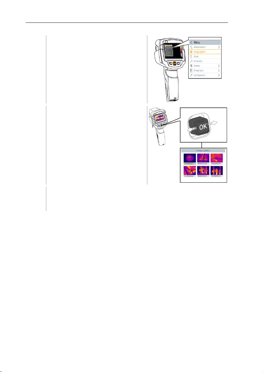
1 - Select the Image gallery function.
All saved images are displayed in the
form of an infrared preview.
2 - Move joystick to select an image.
3 - Press OK to open the selected image.
The image is displayed.
Analyzing an image
Saved images can be analyzed using the Single point measurement, Hotspot,
Coldspot and Differential temperature measuring functions. In saved images
the crosshairs, which mark the measuring point, can be moved using the
joystick.
For a description of the individual functions, please read the information in the
relevant sections.
23
Page 25
7 Performing the measurement
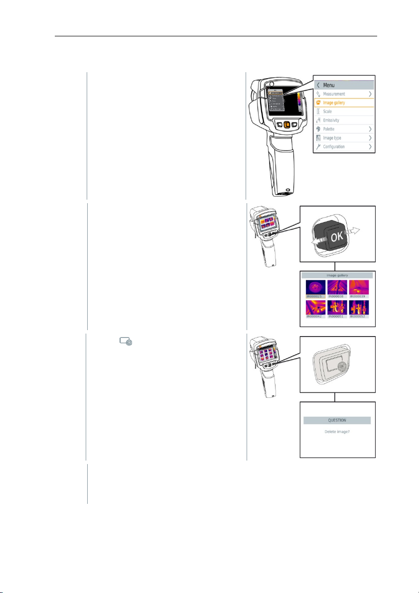
Deleting an image
1 - Select the Image gallery function.
All saved images are displayed in the
form of an infrared preview.
2 - Move joystick to select an image.
3 - Press .
Delete image? is displayed.
4 - Press OK to delete the image.
4.1 - Press Esc to cancel the process.
24
Page 26

7 Performing the measurement
7.4 Setting the scale
Manual scaling can be activated instead of automatic scaling (continuous
automatic adjustment to the current min./max. values). The scale limits can be
set within the measurement range.
The activated mode is displayed bottom right: A automatic scaling, M manual
scaling and S OptiScale (ScaleAssist).
Auto-scaling continuously adjusts the scale to the readings presented,
and the colour assigned to a temperature value changes.
In manual scaling fixed limit values are defined, and the colour
assigned to a temperature value is fixed (important for visual image
comparisons).
Scaling influences the way the infrared image is shown on the display
but does not affect the recorded measuring values.
With ScaleAssist, a standardized scale is set depending on the inside
Setting automatic scaling
and outside temperature.
1 - Select the Scale function.
2 - Move the joystick up or down until Auto is selected and then press
OK.
Automatic scaling is activated. A is displayed bottom right.
Setting manual scaling
The lower limit value, the temperature range (upper and lower limit value
simultaneously) and the upper limit value can be set.
1 - Select the Scale function.
2 - Press OK.
3 - In the mode menu, move the joystick up/down until Manual is
selected.
4 - Move the joystick to the right, select Min.Temp. (lower limit value).
- Move the joystick up/down to set the value.
25
Page 27

7 Performing the measurement
4.1 - Move the joystick to the right, select Min.Temp. (lower limit value)
and Max.Temp. (upper limit value).
- Move the joystick up/down to set the values.
4.2 - Move the joystick to the right, select Max.Temp. (upper limit value).
- Move the joystick up/down to set the value.
4.3 - If necessary, move the joystick to the left, back to the mode menu.
5 - Press OK.
Manual scaling is activated. M is displayed bottom right.
Setting ScaleAssist
The ScaleAssist function calculates a display-neutral scale depending on the
inside and outside temperature. This scale graduation can be used to detect
building defects.
1 - Select the Scale function.
2 - Press OK.
3 - In the mode menu, move the joystick up/down until ScaleAssist is
selected.
4 - Move the joystick to the right, select Indoor temperature.
- Move the joystick up/down to set the value.
5 - Move the joystick to the right, select Outdoor temperature.
- Move the joystick up/down to set the value.
6 - If necessary, move the joystick to the left, back to the mode menu.
7 - Activate ScaleAssist: press Ok.
Manual scaling is activated. S is displayed bottom right.
26
Page 28
7 Performing the measurement
7.5 Setting emissivity and reflected
temperature
This function is only available if the Image type is set to infrared image.
You can choose between user-defined emissivity and 8 materials with
permanently set emissivity. The reflected temperature (RTC) can be set
individually.
Other materials can be imported into the instru
ment from an existing
list using the PC software.
Emissivity information:
The emissivity describes the capability of a body to emit electromagnetic
radiation. This is material-specific and must be adapted for correct
measurement results.
Non-metals (paper, ceramic, gypsum, wood, paints and coatings), plastics and
food have high emissivity, which means that the surface temperature can be
easily measured using infrared.
Because of their low or non-uniform emissivity, bright metals and metal oxides
only have limited suitability for infrared measurement. Highly inaccurate
measurements should be expected. A remedy for this is coatings that increase
emissivity, e.g. paint or emission adhesive (accessory: 0554 0051), which must
be applied to the object to be measured.
The following table gives typical emissivities of important materials. These
values can be used as a guide for user-defined settings.
Material (material temperature) Emissivity
Aluminium, bright rolled (170 °C) 0.04
Cotton (20 °C) 0.77
Concrete (25 °C) 0.93
Ice, smooth (0 °C) 0.97
Iron, emery-ground (20 °C) 0.24
Iron with casting skin (100 °C) 0.80
Iron with rolling skin (20 °C) 0.77
Gypsum (20 °C) 0.90
Glass (90 °C) 0.94
Rubber, hard (23 °C) 0.94
Rubber, soft grey (23 °C) 0.89
27
Page 29

7 Performing the measurement
Material (material temperature) Emissivity
Wood (70 °C) 0.94
Cork (20 °C) 0.70
Radiator, black anodised (50 °C) 0.98
Copper, slightly tarnished (20 °C) 0.04
Copper, oxidised (130 °C) 0.76
Plastics: PE, PP, PVC (20 °C) 0.94
Brass, oxidised (200 °C) 0.61
Paper (20 °C) 0.97
Porcelain (20 °C) 0.92
Black paint, matt (80 °C) 0.97
Steel, heat-treated surface (200 °C) 0.52
Steel, oxidised (200 °C) 0.79
Clay, burnt (70 °C) 0.91
Transformer paint (70 °C) 0.94
Brick, mortar, plaster (20 °C) 0.93
Reflected temperature information:
Using this offset factor, the reflection is calculated out based on the low
emissivity, and the accuracy of the temperature measurement with infrared
measuring instruments is improved. In most cases, the reflected temperature is
identical to the ambient air temperature. Only when objects with strong
emissions at much lower temperatures (such as cloudless skies during outdoor
readings) or much higher temperatures (such as ovens or machines) are in
proximity to the object being measured should the radiation temperature of
these sources be determined and used. The reflected temperature has little
effect on objects with high emissivity.
@ Further information can be found in the Pocket Guide.
7.5.1 Selecting the emissivity
1 - Select the Emissivity function.
2 - Move the joystick up/down to select the required material (with
permanently set emissivity) and then press OK.
7.5.2
28
Page 30

7 Performing the measurement
7.5.3 Customizing the emissivity
1 - Select the Emissivity function.
2 - Move the joystick up/down until User defined is selected.
- Move the joystick to the right until E is selected.
- Manually set value.
3 - Press OK.
7.5.4 Setting the RTC
1 - Select the Emissivity function.
2 - Move the joystick to the right until RTC is selected.
- Manually set value.
3 - Press OK.
7.5.5 Setting ε-Assist
1 - Select the Emissivity function.
2 - Move the joystick to the right until ε-Assist is selected.
3 - Press OK.
4 - Affix ε-marker to the object and measure with the camera.
RTC and emissivity are set automatically.
5 - Press OK.
If it is not physically possible to
same object temperature and reflected temperature, the input field
opens again. The emission value must be input manually.
determine the emissivity due to the
29
Page 31

7 Performing the measurement
7.6 Selecting the colour palette
This function is only available if the Image type is set to infrared image.
1 - Select the Palette function.
2 - Move the joystick up/down to select the required colour palette and
then press OK.
7.7 Image type
The display can be switched between infrared image and real image (digital
camera).
1 - Select the Image type function.
2 - Move the joystick up or down and choose between infrared image or
real image view.
3 - Press OK to confirm the selection.
7.8 Activating humidity, solar or electrical
mode
1 - Open Menu.
2 - Move the joystick down and select Measurement. Then press
OK or move the joystick to the right.
3 - Move the joystick down and select External measurement values.
Then press OK.
4 - Move the joystick up/down and activate Humidity, Current, Voltage,
Solar or Power.
- If no radio probe is connected, enter the values manually.
- If a radio probe is connected, values are transferred automatically.
5 - Press OK to activate the selected Mode.
30
Page 32

7 Performing the measurement
Values for current, voltage and power can be transferred from the
testo 770-3 clamp meter.
7.9 Activating the differential temperature
Differential temperature enables the temperatures between two measuring
points to be calculated.
1 - Open Menu.
2 - Move the joystick down and select Measurement. Then press OK or
move the joystick to the right.
3 - Move the joystick down and select Differential temperature. Then
press OK.
4 - Move the joystick down/up and select which differential temperature
is to be calculated (Point-Point, Point-Probe, Point-Value, Point-
RTC). Then press OK.
4.1 - Point-Point selection:
o Move the joystick to the right -> select measuring point 1 ->
press OK -> move the measuring point to the live image using
the joystick -> press OK.
o Move the joystick to the right -> select measuring point 2 ->
press OK -> move the measuring point to the live image using
the joystick -> press OK.
4.2 - Point-Probe selection:
4.3 - Point-Value selection:
o End measurement: move the joystick to the right, press End.
o Move the joystick to the right -> select measuring point 1 ->
press OK -> move the measuring point to the live image using
the joystick -> press OK.
o End measurement: move the joystick to the right, press End.
o Move the joystick to the right -> select measuring point 1 ->
press OK -> move the measuring point to the live image using
the joystick -> press OK.
o Move the joystick to the right, set the value manually.
o End measurement: move the joystick to the right, press End.
31
Page 33

7 Performing the measurement
4.4 - Point-RTC selection:
o Move the joystick to the right -> select measuring point 1 ->
press OK -> move the measuring point to the live image using
the joystick -> press OK.
o Move the joystick to the right, set the value manually.
o End measurement: move the joystick to the right, press End.
7.10 Configuration
7.10.1 Settings
Country settings
The user interface language can be set.
1 - Select the Country setti
ngs function.
2 - Move the joystick up/down to select the required language and
then press OK.
Set time/date
Time and date can be set. The time and date format are set automatically
based on the selected user interface language.
1 - Select the Set time/date function.
2 - Move the joystick to the right/left to select the required setting
option.
3 - Move the joystick up/down to set the value.
4 - After setting all values, press OK.
Temperature unit
The temperature unit can be set.
1 - Open the Temp
erature unit submenu. For how to proceed: see
Getting to know the menu.
2 - Move the joystick up/down to select the required unit and then
press OK.
32
Page 34

7 Performing the measurement
Power-save options
The illumination intensity of the display can be set. A lower intensity increases
the battery life.
The time until automatic switch-off can be set.
1 - Select the Power-save options function.
2 - Move the joystick up/down to select the required intensity level
and then press OK.
7.10.2 SuperResolution
SuperResolution is a technology to improve image quality. Each time an image
is recorded, a sequence of images is saved on the thermal imager and used to
calculate an image with four times more readings, with the aid of the camera ,
the App or PC software (no interpolation). The geometric resolution (IFOV) is
improved by a factor of 1.6.
To use the function, the following conditions must be fulfilled:
∑ The camera is hand-held.
∑ The objects to be imaged do not move.
1 - Open the SuperResolution function.
2 - Press OK to activate or disable the function.
7.10.3 Save JPEG function
Infrared images are saved in BMT (image with all temperature data) format. The
image can also be saved in JPEG format (without temperature data) at the
same time. The image content corresponds to the infrared image shown on the
display, including scale display and image marks for the selected measuring
functions. The JPEG file is saved under the same file name as the associated
BMT file and can be opened on the PC, even without using the IRSoft PC
software.
1 - Open the Save JPEG function.
2 - Press OK.
3 - Move the joystick up/down until On/Off is selected.
33
Page 35

7 Performing the measurement
4 - Press OK.
5 - Add a date/time stamp to a JPEG file if required. Turn function on or
off for this.
7.10.4 Connectivity
Enable/disable WLAN or Bluetooth®
1 - Menu -> Configuration -> Connectivity
2 - Move the joystick to the right (>).
- Select WLAN and press OK to enable (✔) or disable the function.
- Select Bluetooth and press OK to enable (✔) or disable the
function.
3 - Press Esc to cancel the process.
If there is an
activated in addition, the Bluetooth data transfer is continued.
However, it is not possible to establish a new connection to a humidity
probe.
active Bluetooth connection and a WLAN connection is
7.10.5 Ambient conditions
Measurement deviations arising due to high humidity or large distances to the
object to be measured can be corrected. Correction parameters must be
entered for this.
If the camera is connected to an optional radio humidity probe, the ambient
temperature and humidity are transferred automatically.
Values for ambient temperature (Temperature) and ambient humidity (Humidity)
can be set manually.
1 - Menu -> Configuration -> Ambient conditions
2 - Move the joystick up/down to set the temperature value.
3 - Move the joystick to the right.
4 - Move the joystick up/down to set the humidity value.
5 - Press OK.
34
Page 36

7 Performing the measurement
7.10.6 Info
The following instrument information is displayed:
∑ Device data (e.g. serial number, device name, firmware version)
∑ Options
∑ Measurement functions
∑ WLAN
∑ Radio certifications
∑ Legal information
7.10.7 Fullscreen mode
The scale and the quick select button function indicator can be hidden.
1 - Select the Fullscreen mode function.
When Fullscreen Mode is activated, the scale and icon for the quick
select button are hidden. When a key is pressed, these elements are
displayed briefly.
7.10.8 Reset options
Reset counter
After a reset, the consecutive numbering of images starts again from
the beginn
same number are overwritten!
Back up all saved images before resetting the counter to prevent
possible overwriting.
1 - Menu -> Configuration -> Reset counter
2 - Select the Reset counter function.
Reset image counter? is displayed.
3 - Press OK to reset the counter.
3.1 - Press Esc to cancel the process.
ing. When saving images, already saved images with the
35
Page 37

7 Performing the measurement
Factory settings
The instrument settings can be reset to the factory settings.
Time/date, country settings and counter are not reset.
1 - Menu -> Configuration -> Reset options.
2 - Select the Factory settings function.
Apply factory settings? is displayed.
3 - Press OK to apply factory settings.
2.1 - Press Esc to cancel the process.
Formatting
The image memory can be formatted.
When formatting, all data saved in the memory is lost.
Back up all saved images before formatting to prevent loss of data.
Formatting does not reset the counter.
1 - Menu -> Configuration -> Reset options.
2 - Select the Format function.
Format memory? is displayed.
3 - Press OK to format the memory.
3.1 - Press Esc to cancel the process.
36
Page 38
8 Maintenance
8 Maintenance
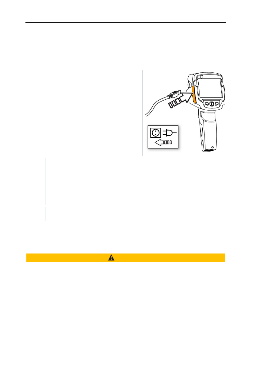
8.1 Charging the rechargeable battery
1
- Open the cover of the interface
terminal.
2
- Connect the recharger cable to the
Micro-USB interface.
3
- Connect the mains unit to a mains
socket.
The charging process will start.
If the battery has been completely drained, the charging time is
approx. 5 hours.
The charge status is not displayed while the instrument is switched
off.
4
- Switch on the instrument to call up the charge status.
@ For other battery charging options, .
8.2 Changing the rechargeable battery
WARNING
Serious risk of injury to the user and/or destruction of the instrument
> There is a risk of explosion if the battery is replaced with one that is the
wrong type.
> Dispose of spent/faulty batteries in accordance with the relevant legal
specifications.
37
Page 39
8 Maintenance
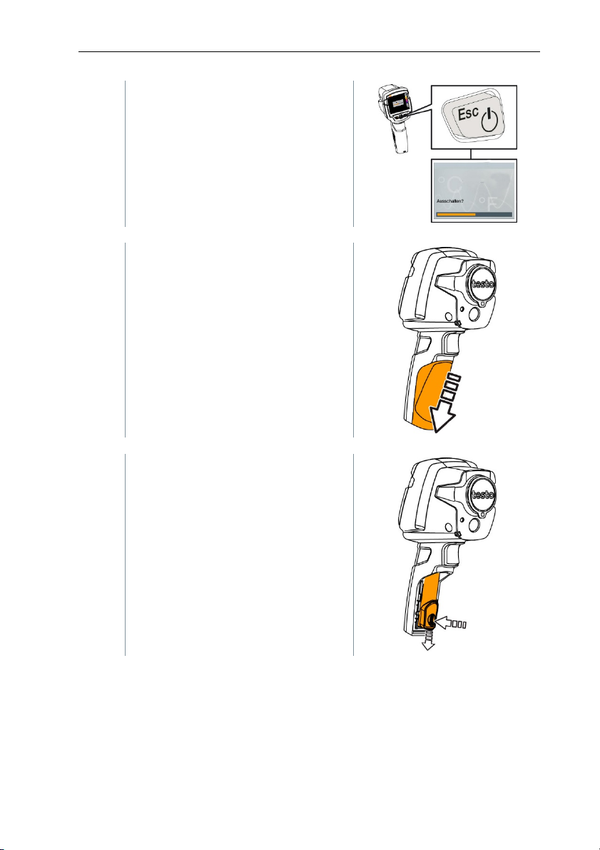
1
- Switch the instrument off.
2
- Open the battery compartment.
38
3
- Release the b
attery and remove.
Page 40
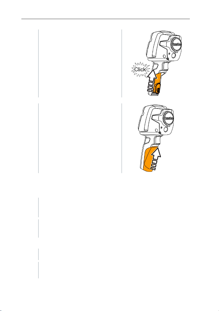
4
- Insert new battery and slide upwards
until it clicks into place.
5
- Close the battery compartment.
8 Maintenance
8.3 Cleaning the instrument
Cleaning the instrument housing
- The interface terminal is closed.
- The battery compartment is closed.
1
- Rub down the surface of the instrument with a damp cloth. Use mild
household cleaning agents or soapy water for this.
Cleaning the lens and display
1
- If the len
2 - If the display is dirty, clean it with a cleaning cloth (e.g. microfibre
cloth).
s is dirty, clean it with a cotton bud.
39
Page 41

8 Maintenance
8.4 Firmware Update
The current Firmware version can be found on www.testo.com.
There are two update options:
∑ Update with IRSoft or
∑ Update directly with the thermal imager
Downloading the Firmware
1 - Download the following Firmware: Firmware-testo-865-872.exe
2 - Unpack file: doubleclick the exe-file
FW_T87x_Vx.xx.bin is stored in a selected file.
8.4.1 Update with IRSoft
8.4.1.1 Prepare the Camera
Battery is fully charged or charger is connected to the camera.
1 - Connect computer to camera with USB cable.
2 - Switch on camera.
Firmware is downloaded completely.
8.4.1.2 Execute Update
- IRSoft is activated.
1 - Select Camera -> Configuration.
2 - Click Configure camera.
Window Camera Settings is opened.
40
3 - Camera Settings -> select Firmware Update -> OK.
FW_T87x_Vx.xx.bin is displayed.
4 - Select Open.
Page 42

Firmware Update is executed.
Automatic restart of the thermal imager. Update executed
successfully.
Camera coul possible display: Firmware Update finished. Please
restart the device. Restart will not be done.
Action:
- Switch off the camera after 10 s and switch on after 3 s.
The current Firmeware version is displayed.
8.4.2 Update with the camera
8.4.2.1 Prepare camera
- Battery is fully charged or charger is connected to the camera.
1 - Switch on camera.
2 - Open the interface cover.
3 - Connect computer with the camera through USB cable.
8 Maintenance
Camera is displayed as storage media device in
Windows-Explorer.
8.4.2.2 Execute Update
1 - FW_T87x_Vx.xx.bin- with Drag & Drop into the storage media
device.
2 - Eject storage media device.
3 - Disconnect USB connection.
4 - Switch off camera.
5 - Switch on camera: Update is executed.
6 - See Progress display.
Update successfully done. Current Firmeware version
is displayed.
41
Page 43
9 Tips and assistance
A
9 Tips and assistance
9.1 Questions and answers
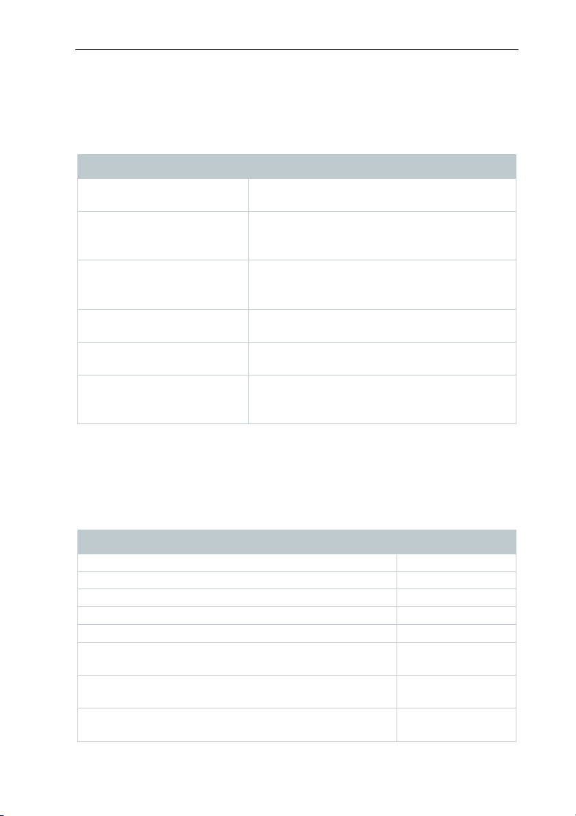
Question Possible cause / solution
Error! Memory full! is
displayed.
Error! Permissible
instrument temperature
exceeded! is displayed.
~ is displayed before a value.
--- or +++ is displayed
instead of a value.
xxx is displayed instead of a
value.
utomatic zeroing (audible
"click" and brief image freeze)
is carried out very frequently.
If we have not been able to answer your question, please contact your dealer or
Testo Customer Service. You will find contact details on the back of this
document or on the website www.testo.com/service-contact.
Insufficient memory available: Transfer images
to the PC or delete.
Switch off the camera, allow the instrument to
cool down and observe the permissible
ambient temperature.
Value is outside the measuring range:
extended display range with no guarantee of
accuracy.
Value is outside the measuring range and the
extended display range.
Value cannot be calculated: check parameter
settings for plausibility.
Camera is still in its warm-up period (takes
approx. 90 seconds): Wait until the warm-up
period has passed.
9.2 Accessories and spare parts
Description Article no.
Battery charging station 0554 1103
Spare rechargeable battery 0515 5107
Holster case 0554 7808
Additional markers for E-Assist function (10 off) 0554 0872
Emission tape 0554 0051
ISO calibration certificate: Calibration points at 0 °C,
25 °C, 50 °C
ISO calibration certificate: Calibration points at 0 °C,
100 °C, 200 °C
ISO calibration certificate: Freely selectable calibration
points in the range -18 °C to 250 °C
42
0520 0489
0520 0490
0520 0495
Page 44
10 Authorisations and certification
For further accessories and spare parts, please refer to the product catalogues
and brochures or look up at www.testo.com.
10 Authorisations and certification
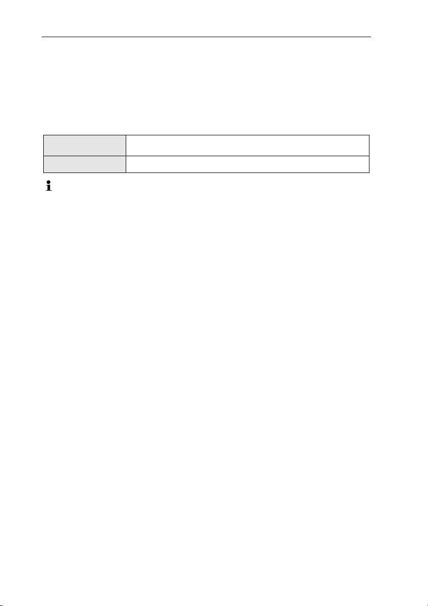
Product testo 871
Mat.-No. 0560 8711, 0560 8712
The use of the wireless module is subject to the regulations and stipulations of the respective
country of use, and the module may only be used in countries for which a country certification has been
granted. The user and every owner has the obligation to adhere to these regulations and prerequisites
for use, and acknowledges that the re-sale, export, import etc. in particular in countries without wireless
permits, is his responsibility.
43
Page 45
10 Authorisations and certification
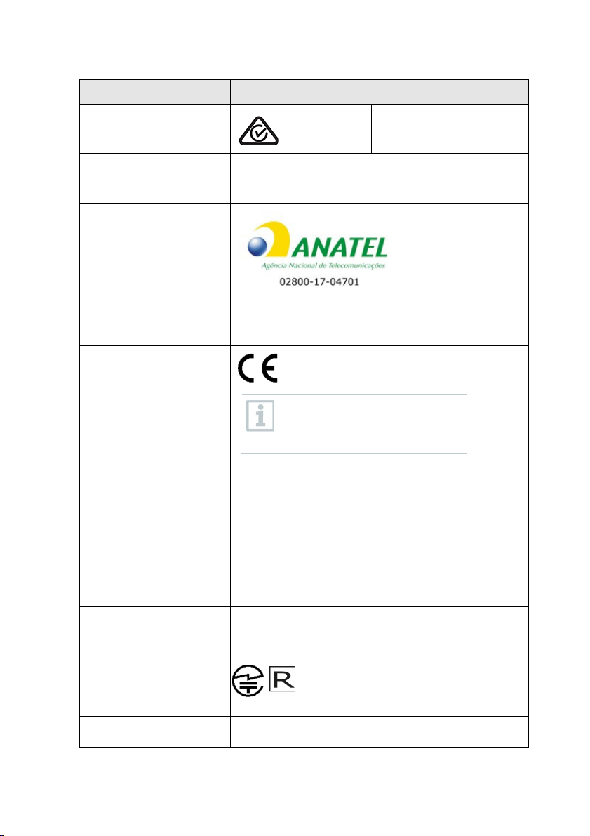
Country Comments
Australia
Canada Contains IC: 5969A-TIWI101
Brazil
Europa + EFTA
Product IC: 6127B-2016TIFAM
IC Warnings
Este equipamento opera em caráter secundário, isto é, não tem
direito a proteção contra interferência prejudicial, mesmo de
estações do mesmo tipo, e não pode causar interferência a
sistemas operando em caráter primário.
The EU Declaration of Conformity can be
found on the testo homepage
www.testo.com under the product
specific downloads.
countries
EU
Belgium
Estonia (EE), Finland (FI), France (FR), Greece (GR), Ireland (IE),
Italy (IT), Latvia (LV), Lithuania (LT), Luxembourg (LU), Malta
(MT), Netherlands (NL), Austria (AT), Poland (PL), Portugal (PT),
Romania (RO), Sweden (SE), Slovakia (SK), Slovenia (SI), Spain
(ES), Czech Republic (CZ), Hungary (HU), United Kingdom (GB),
Republic of Cyprus (CY).
:
(BE), Bulgaria (BG), Denmark (DK), Germany (DE),
E 1561
EFTA countries:
Iceland, Liechtenstein, Norway, Switzerland
India Authorized
Japan
Japan Information
Russia Authorized
44
209-J00157
Page 46
10 Authorisations and certification
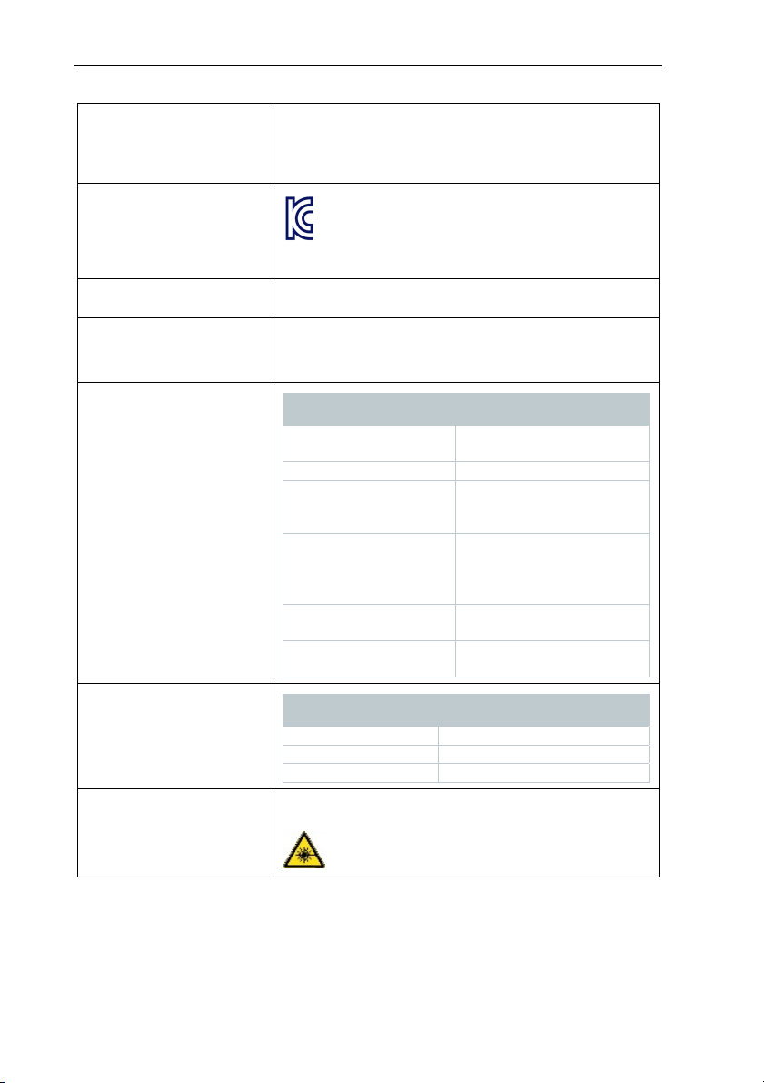
South Africa ICASA ID
South Korea
Turkey Authorized
USA contains FCC ID: TFB-TIWI1-01
WLAN /
Bluetooth®
Information
testo 868: TA-2017/917
testo 871: TA-2017/916
testo 872: TA-2017/918
testo 871: MSIP-REM-te2-Testo871
KCC Warning
Product FCC ID: WAF-2016TIFAM
FCC Warnings
Feature Values
WLAN range
Bluetooth® range
radio type TiWi-BLE
radio class WLAN 2.4 GHz IEEE 802.11 b/g
radio module company LSR
RF Band BT LE: 2402 – 2480MHz
power output [E.I.R.P] BT LE: 10dBm
typical 15 m
typical 5 m
Bluetooth® 2.1 + EDR and
Low Energy (BLE) 4.0
W66 N220 Commerce Court
Cedarburg,
WI 53012-2636 USA
WLAN: 2412 – 2480MHz
WLAN: 20dBm
Bluetooth® SIG Listing
Laser * Conform to IEC / EN 60825-1:2014
* Use only in produc
Australia
IC Wa
rnings
RSS-Gen & RSS-247 statement:
This device complies with Industry Canada licence-exempt RSS standard(s).
Operation is subject to the following two conditions:
ts of testo 868, testo 871 and testo 872 for Europe + EFTA countries, Turkey and
Feature Values
QD ID 90590
Declaration ID D030647
member company Testo SE & Co. KGaA
Laser class 2
Do not stare into the beam!
45
Page 47

10 Authorisations and certification
(1) this device may not cause interference, and
(2) this device must accept any interference, including interference that may cause undesired
operation of the device.
Le présent appareil est conforme aux CNR d'Industrie Canada applicables aux appareils radio
exempts de licence.
L'exploitation est autorisée aux deux conditions suivantes :
(1) l'appareil ne doit pas produire de brouillage, et
(2) l'utilisateur de l'appareil doit accepter tout brouillage radioélectrique subi, même si le brouillage
est susceptible d'en compromettre le fonctionnement.
Caution: Radio Frequency Radiation Exposure
This equipment complies with IC radiation exposure limits set forth for an uncontrolled environment
and meets the IC radio frequency (RF) Exposure Guidelines. This equipment should be installed and
operated keeping the radiator at least 12 cm or more away from person´s body in normal use position.
Co-Location:
This transmitter must not be co-located or operated in conjunction with any other antenna or
transmitter.
Attention : exposition au rayonnement de radiofréquences
Cet équipement est conforme aux limites d'exposition aux radiofréquences IC fixées pour un
environnement non contrôlé et aux Lignes directrices relatives à l'exposition aux radiofréquences (RF).
Cet équipement devrait être installé et utilisé à une distance d'au moins 12 cm d'un radiateur ou à une
distance plus grande du corps humain en position normale d'utilisation.
Co-location
Ce transmetteur ne peut pas être installé en colocation ou être utilisé avec une autre antenne ou
transmetteur, quel qu'en soit le type.
FCC Warnings
Information from the FCC (Federal Communications Commission)
For your own safety
Shielded cables should be used for a composite interface. This is to ensure continued protection
against radio frequency interference.
FCC warning statement
This equipment has been tested and found to comply with the limits for a Class B digital device,
pursuant to Part 15 of the FCC Rules. These limits are designed to provide reasonable protection
against harmful interference in a residential installation. This equipment generates, uses and can
radiate radio frequency energy and, if not installed and used in accordance with the instructions, may
cause harmful interference to radio communications. However, there is no guarantee that interference
will not occur in a particular installation. If this equipment does cause harmful interference to radio or
television reception, which can be determined by turning the equipment off and on, the user is
encouraged to try to correct the interference by one or more of the following measures:
- Reorient or relocate the receiving antenna.
- Increase the separation between the equipment and receiver.
- Connect the equipment into an outlet on a circuit different from that to which the receiver is
connected.
- Consult the dealer or an experienced radio/TV technician for help.
Caution
Changes or modifications not expressly approved by the party responsible for compliance could void
the user's authority to operate the equipment. Shielded interface cable must be used in order to
comply with the emission limits.
Warning
46
Page 48

10 Authorisations and certification
This device complies with Part 15 of the FCC Rules. Operation is subject to the following two
conditions:
(1) this device may not cause harmful interference, and
(2) this device must accept any interference received, including interference that may cause undesired
operation.
Caution: Radio Frequency Radiation Exposure
This equipment complies with FCC radiation exposure limits set forth for an uncontrolled environment
and meets the FCC radio frequency (RF) Exposure Guidelines. This equipment should be installed and
operated keeping the radiator at least 12 cm or more away from person´s body in normal use position.
Co-Location:
This transmitter must not be co-located or operated in conjunction with any other antenna or
transmitter.
Japan Information
当該機器には電波法に基づく、技術基準適合証明等を受けた特定無線設備を装着している。
KCC Warning
해당 무선 설비는 운용 중 전파혼신 가능성이 있음。
47
Page 49

0970 8710 e
Test Equipment Depot - 800.517.8431 - 5 Commonwealth Ave, MA 01801
TestEquipmentDepot.com
n 04
 Loading...