

Page 1
99 Washington Street
Melrose, MA 02176
Phone 781-665-1400
Toll Free 1-800-517-8431
Visit us at www.TestEquipmentDepot.com
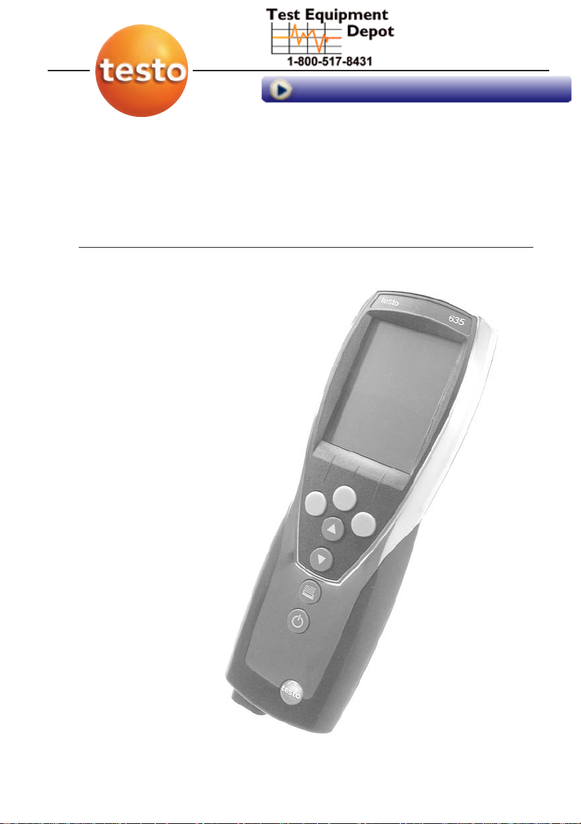
Humidity/temperature/pressure dew point measuring instrument
Instruction manual
testo 635
Contents
General notes ....................................................32
1. Safety instructions..............................................34
2. Intended purpose ..............................................35
3. Product description............................................36
3.1 Display and control elements ........................................36
3.2 Interfaces ......................................................................38
3.3 Voltage supply ..............................................................38
4. Commissioning ..................................................39
5. Operation ..........................................................40
5.1 Connecting a probe ......................................................40
5.2 Switching on/off ............................................................40
5.3 Display light ..................................................................41
6. Setting the instrument ........................................42
6.1 Configuration menu ......................................................42
6.1.1 Profile..............................................................................42
6.1.2 Units ..............................................................................43
6.1.3 Device ............................................................................43
6.1.4 Probe..............................................................................45
6.1.5 Language........................................................................46
6.2 Main menu....................................................................47
6.2.1 Memory (635-2 only) ......................................................48
6.2.2 Measuring program (635-2 only) ....................................49
6.2.3 Mean (635-2 only) ..........................................................50
6.2.4 Calculation ......................................................................51
6.2.5 Material ..........................................................................52
6.2.6 Cyclical Print (635-1 only) ..............................................53
7. Measuring ..........................................................54
8. Care and maintenance ......................................56
9. Questions and answers......................................57
10. Technical data ....................................................58
11. Accessories / spare parts ..................................59
Page 2
General notes32
General notes
This chapter provides important advice on using this documentation.
The documentation contains information that must be applied if the product is
to be used safely and efficiently.
Please read this documentation through carefully and familiarise yourself with
the operation of the product before putting it to use. Keep this document to
hand so that you can refer to it when necessary.
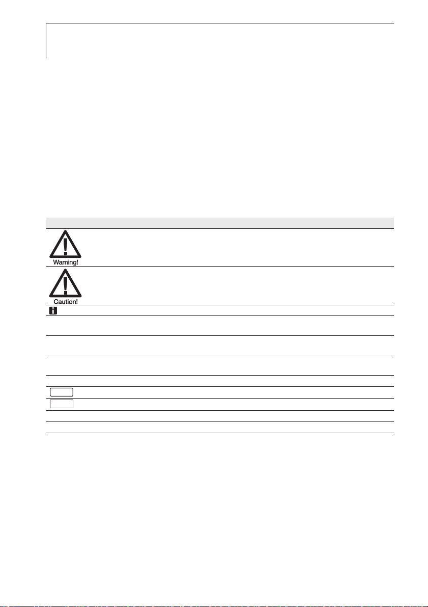
Identification
Representation Meaning Comments
Warning advice: Warning! Read warning advice carefully and take the precautionary measures
indicated! Serious physical injury could occur if you do not take the
precautionary measures indicated.
Warning advice: Caution! Read warning advice carefully and take the precautionary measures
Note Offers helpful tips and information.
±, 1, 2 Objective Denotes the objective that is to be achieved via the steps described.
Condition A condition that must be met if an action is to be carried out as
i, 1, 2, ... Step Carry out steps. Where steps are numbered,you must always follow
Text Display text Text appears on the instrument display.
Button
- Result Denotes the result of a previous step.
º Cross-reference Refers to more extensive or detailed information.
Control button Press the button.
Function button Press the button.
indicated! Slight physical injury or damage to equipment could occur
if you do not take the precautionary measures indicated.
Where steps are numbered, you must always follow the order given!
described.
the order given!
Test Equipment Depot - 800.517.8431 - 99 Washington Street Melrose, MA 02176
TestEquipmentDepot.com
Page 3
General notes 33
Short form
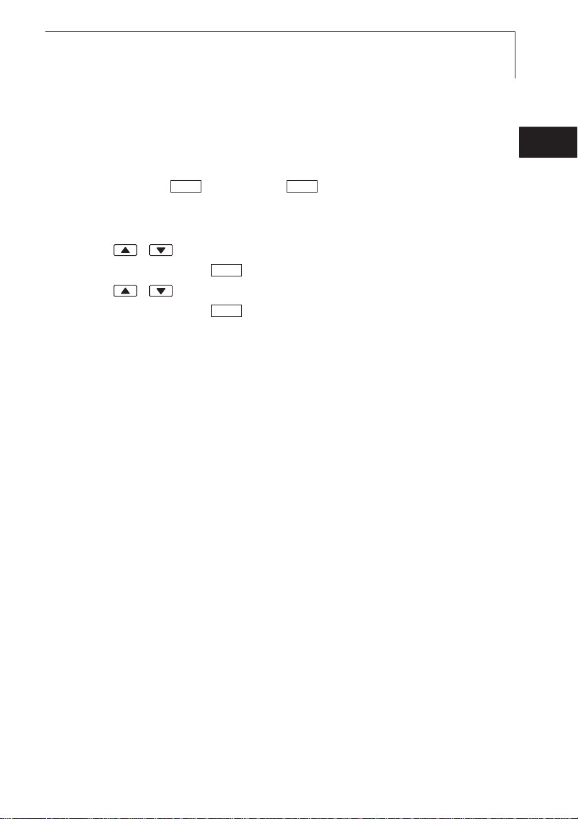
This document uses a short form for describing operating steps (e.g. calling up
a function).
Example: Calling up the “Instrument data” function
Short form: Device ¬¬Inst.data ¬ .
1) (2) (3) (4)
(
OKOK
Steps required:
1 Press / to select the Device function.
2 Confirm selection with .
3 Press / to select the Inst.data function.
4 Confirm selection with .
OK
OK
de
enfresitptsvnl????
Page 4

1. Safety instructions34
1. Safety instructions
This chapter gives general rules which must be followed and observed if the
product is to be handled safely.
Avoid personal injury/damage to equipment
i Do not use the measuring instrument and probes to measure on or near live
parts.
i Never store the measuring instrument/measuring cells together with solvents
and do not use any desiccants.
Product safety/preserving warranty claims
i Operate the measuring instrument only within the parameters specified in the
Technical data.
i Always use the measuring instrument properly and for its intended purpose.
Do not use force.
i Do not expose handles and feed lines to temperatures in excess of 70 °C
unless they are expressly permitted for higher temperatures. Temperatures
given on probes relate only to the measuring range of the sensors.
i Open the instrument only when this is expressly described in the
documentation for maintenance or repair purposes.
Carry out only the maintenance and repair work that is described in the
documentation. Follow the prescribed steps when doing so. For safety
reasons, use only original spare parts from Testo.
Ensure correct disposal
i Take faulty rechargeable batteries/spent batteries to the collection points
provided for them.
i Send the product back to Testo at the end of its useful life. We will ensure
that it is disposed of in an environmentally friendly manner.
Page 5

2. Intended purpose 35
2. Intended purpose
This chapter gives the areas of application for which the product is intended.
Use the product only for those applications for which it was designed. Ask
Testo if you are in any doubt.
testo 635 is a compact measuring instrument for measuring temperature,
humidity and the pressure dew point.
The product was designed for the following tasks/applications:
· Measuring room climate
· Regulating and inspecting ventilation and air-conditioning installations
· Measuring the pressure dew point in compressed air systems
The product should
· Areas at risk of explosion.
· Diagnostic measurements for medical purposes.
not
be used in the following areas:
de
enfresitptsvnl????
Page 6
3. Product description36
3. Product description
This chapter provides an overview of the components of the product and their
functions.
3.1 Display and control elements
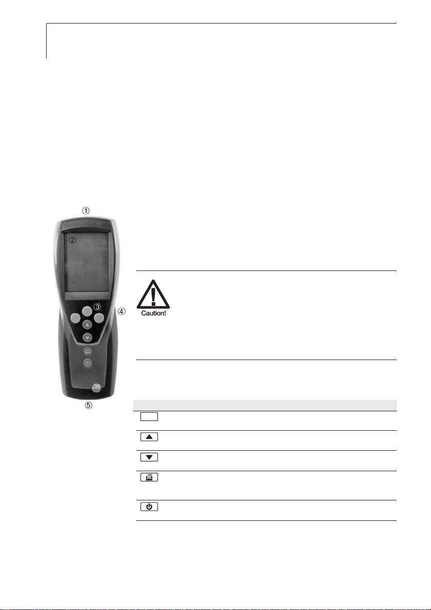
Overview
Infrared, USB interface
Display (light can be activated)
Control buttons
Rear: Battery and radio module compartment, holding
magnets
Strong magnets
Damage tto oother iinstruments!
i
Keep a safe distance from products which
could be damaged by magnetism (e.g.
monitors, computers, pacemakers, credit
cards).
Probe socket(s)
Button functions
Button Functions
Function button (3x): The function depends on the button assignment
at the time
Change display of the 1
In configuration mode: Increase value, select option
Change display of the 2
In configuration mode: Decrease value, select option
Print data
635-1 only: If the Cyclical Printing function is activated, the
programmed measuring program is started.
Switch instrument on, switch display light on/off;
switch instrument off (press and hold)
st
reading line
nd
reading line
Page 7
3. Product description 37
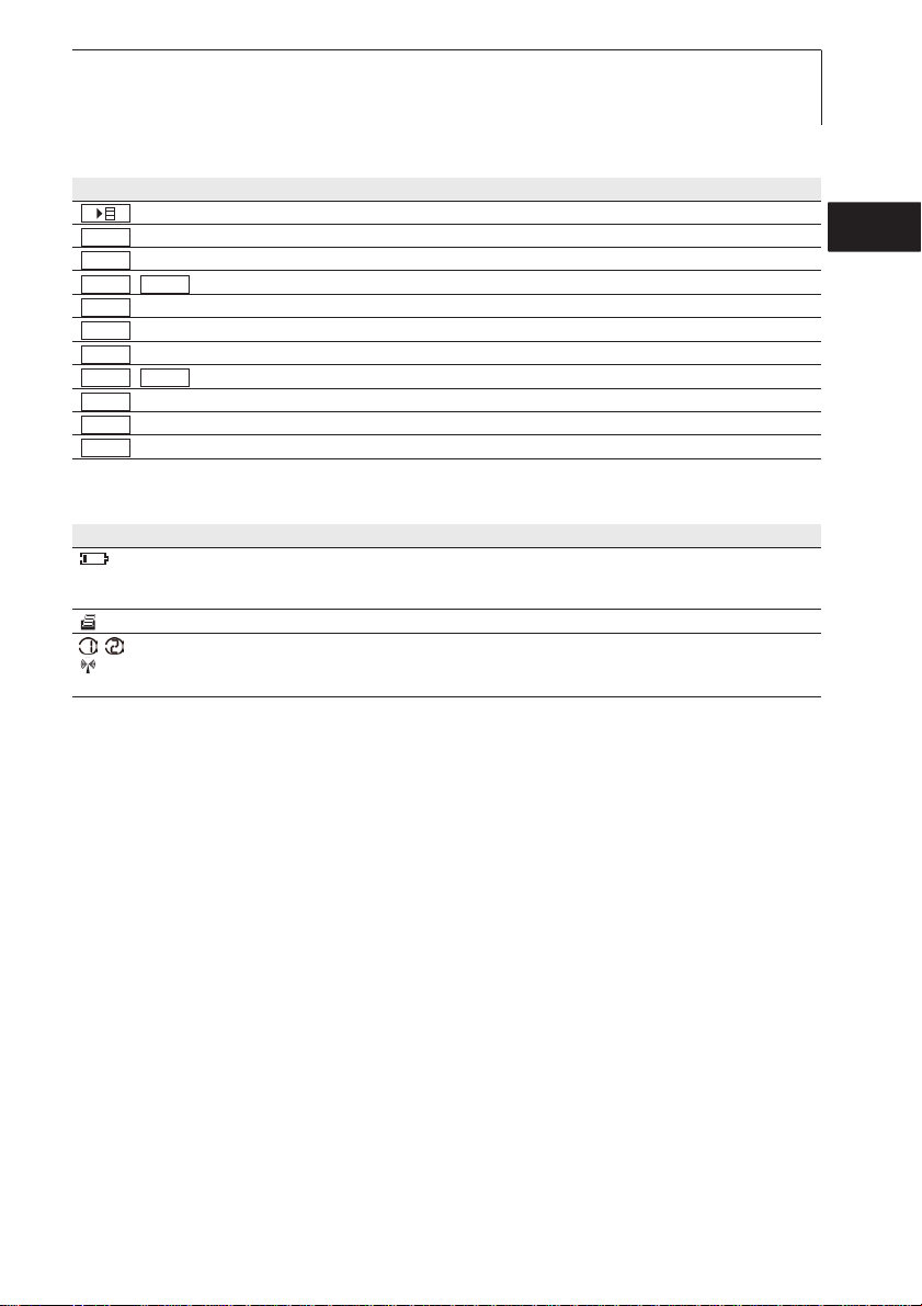
Function buttons (Function dependant on profile and setting)
Button Functions
Open (main) menu
OK
ESC
ACTHold
/ Hold value/display current measurement value
Reset
Mean
Measp
EndStart
/ Start/end test series (635-2 only)
Save
Mat
Radio
Enter confirmation
Cancel
Reset max./min. values to current measurement value
Open menu item “Multi-point mean calculation“
Open menu item “Measuring program“ (635-2only)
Save values (635-2 only)
Open menu item “Material”
Open menu item “Radio”
Important displays
Display Meaning
Battery capacity (only for operation by battery/rechargeable battery):
· 4 segments in the battery symbol are lit: Instrument battery is fully charged
· No segments in the battery symbol are lit: Instrument battery is almost spent
(flashing) Print function: Data are sent to the printer
, Measurement channel no.: Channel 1, channel 2.
If a measurement channel is a radio channel, the radio symbol lights up as well as the
measurement channel no.
de
enfresitptsvnl????
Test Equipment Depot - 800.517.8431 - 99 Washington Street Melrose, MA 02176
TestEquipmentDepot.com
Page 8

3. Product description38
3.2 Interfaces
Infrared interface
Measurement data can be sent to a Testo printer via the infrared interface on
the head of the instrument.
USB interface
The mains unit (accessory part) can be connected to the head of the
instrument via the USB interface to power the instrument.
Instruments with a memory: Measurement/instrument data can be exchanged
with a PC via the USB interface.
Probe socket(s)
Plug-in measuring probes can be connected via the probe socket(s) on the
base of the instrument. The instrument is a HighPower device, possibly an
additional USB-Hub is required!
Radio module (accessory part)
Radio probes may only be used in countries in which they have been Type
Approved (see application information of the radio probe).
Up to three radio probes can be connected via the radio module.
3.3 Voltage supply
Voltage is supplied via three mignon batteries (included in delivery) or
rechargeable batteries or through a mains unit (accessory part). It is not
possible to charge rechargeable batteries in the instrument.
Page 9

4. Commissioning 39
4. Commissioning
This chapter describes the steps required to commission the product.
Removing tthe pprotective ffilm oon tthe ddisplay:
²
i Pull the protective film off carefully.
Inserting bbatteries/rechargeable bbatteries aand aa rradio mmodule ((accessory
²
part):
1 Undo the two screws on the rear of the instrument and lift off the battery
compartment cover.
2 Insert batteries/rechargeable batteries (3x mignon) into the battery
compartment. Observe the polarity!
3 Push the radio module (accessory part) into the radio module
compartment until it engages in place. Note the guide groove.
4 Replace the battery compartment cover, press down and secure by
tightening the two screws.
de
enfresitptsvnl????
Page 10

5. Operation40
5. Operation
This chapter describes the steps that are executed frequently when using the
product.
5.1 Connecting a probe
Plug-in probes
Plug-in probes must be connected before the measuring instrument is
switched on so that they are recognised by the instrument.
i Insert the connector of the probe into the probe socket of the measuring
instrument.
Radio probes
Radio probes may only be used in countries in which they have been Type
Approved (see application information of the radio probe).
A radio module (accessory part) is required for the use of radio probes. The
radio module must be connected before the measuring instrument is switched
on so that it is recognised by the measuring instrument.
Each radio probe has a probe ID (identification number) which must be set in
configuration mode.
º See chapter PROBE, p. 45.
5.2 Switching on/off
Switching tthe iinstrument oon:
²
i Press .
- Measurement view is opened: The current reading is displayed, or
---- lights up if no reading is available.
Instruments with a memory: The activated location is displayed
(topmost line).
-oor-
The instrument is switched on for the first time, a reset was carried out or
the power supply was interrupted for a lengthy period of time:
- The Language function is opened.
º See the chapter
LANGUAGE, p. 46.
Page 11
Switching tthe iinstrument ooff:
²
i Press and hold (for approx. 2s) until the display goes out.
5.3 Display light
Switching tthe ddisplay llight oon/off:
²
The instrument is switched on.
i Press .
5. Operation 41
de
enfresitptsvnl????
Page 12
6. Setting the instrument42
6. Setting the instrument
This chapter describes the steps that are required in order to adapt the
measuring instrument for specific measuring tasks.
6.1 Configuration menu
The basic settings for the measuring instrument are performed in the
configuration menu.
Opening tthe cconfiguration mmenu:
²
The instrument is in measurement view.
i Press and hold (approx. 2s) until config. is displayed.
Press to go one menu level back. To leave the configuration menu,
press several times until the instrument changes to measurement view.
6.1.1 Profile
ESC
ESC
The instrument has predefined measurement profiles that are tailored to
specific areas of application.
The profile setting influences the following points in measurement mode:
· Assignment of the function buttons
· Number of predefined functions
· Structure of the main menu
All functions are available in the standard profile. In the application-specific
measurement profiles, the available functions are reduced to only those that are
needed to ensure speedier access.
Setting aa pprofile:
²
The configuration menu is open, config. is displayed.
1 Profile ¬ .
2 Select the desired profile with / and confirm with .
OK
OK
Page 13
6. Setting the instrument 43
6.1.2 Units
Predefined systems and individual setting options:
Parameter ISO system US system Individual setting options
Temperature °C °F °C, °F
Pressure hPa inchH2O mbar, Pa, hPa, kPa, inchH2O
Setting uunits:
²
The configuration menu is open, config. is displayed.
1 Units ¬ .
2 Press / ISO/US (to set the system) or a parameter (to set
individually) and confirm with .
3 Set the system of units or the desired unit with / and confirm
with .
OK
OK
OK
6.1.3 Device
Instrument data
Displaying iinstrument ddata:
²
The configuration menu is open, config. is displayed.
1 Device ¬¬Inst.data ¬ .
- The firmware version and the serial number of the instrument are
displayed.
OKOK
de
enfresitptsvnl????
Date/Time
Setting tthe ddate/time:
²
The configuration menu is open, config. is displayed.
1 Device ¬¬date/time ¬ .
2 Use / to set the value for year and confirm with .
3 Set the other values as described in step 2.
OKOK
OK
Page 14
6. Setting the instrument44
Battery type
To ensure that the battery capacity is displayed correctly, the battery type used
must be set.
Setting tthe bbattery ttype:
²
The configuration menu is open, config. is displayed.
1 Device ¬¬Bat-type ¬ .
2 Press / Battery or ReBa and confirm with .
OKOK
OK
Auto OFF
If Auto OFF is switched on, the instrument switches itself off automatically after
10min if no button is pressed. Exception: Cyclical printing (instruments without
a memory) or a measuring program (instruments with a memory) is active.
Switching AAuto OOFF oon/off:
²
The configuration menu is open, config. is displayed.
1 Device ¬¬Auto OFF ¬ .
2 Press / to select On or Off and confirm with .
OKOK
OK
Reset
When a reset is carried out, the instrument is reset to the default settings, all
settings/data are deleted. Exception: Language, Date/Time.
Resetting:
²
The configuration menu is open, config. is displayed.
1 Device ¬¬reset ¬ .
2 Reset with or cancel the reset with .
OKOK
ESCOK
Te-Type
The probe characteristic curves stored in the instrument can be set for the
probe type used.
Setting pprobe ttype:
²
The configuration menu is open, Config. is displayed.
1 Probe ¬¬Te-Type ¬ .
2 Select the desired probe type with / and confirm with .
OKOK
OK
Page 15
6. Setting the instrument 45
6.1.4 Probe
RadioC
Radio probes may only be used in countries in which they have been Type
Approved (see application information of the radio probe).
A radio module (accessory part) is required for the use of radio probes. The
instrument can establish a connection with a maximum of three radio probes.
Each radio probe has a probe ID (RF ID). This consists of the last 3 digits of the
serial no. and the position of the slide switch (H or L) in the radio probe.
Setting uup aa rradio pprobe:
²
A radio module (accessory part) is inserted in the instrument.
º See chapter COMMISSIONING, p. 39.
The configuration menu is open, config. is displayed.
The radio probe is switched on and the transfer rate is set to 2 readings
per second (see the advice on using the radio probe).
1 Probe ¬¬RadioC ¬ .
2 Press / to select the desired channel no. for the radio probe (P. 1 ,
P. 2 or P. 3 ) and confirm with .
- The instrument searches for switched-on radio probes in the receiving
range.
- The probe IDs of the radio probes found are displayed.
OKOK
OK
de
enfresitptsvnl????
If no radio probes were found, this may be because of the following:
· The radio probe is not switched on or the battery of the radio probe is
spent.
· The radio probe is outside the range of the measuring instrument.
· Sources of interference are influencing the radio transmission (e.g.
reinforced concrete, metal objects, walls or other barriers between
transmitter and receiver, other transmitters of the same frequency,
strong electromagnetic fields).
i If necessary, rectify the possible causes of the fault in radio
transmission.
Alternatively, the probe ID can also be entered manually.
MAN
i ¬ Press / to enter the probe ID.
3 Press / to select the probe that is to be assigned to the chosen
channel no.
4 Assign the radio probe to the chosen channel no. with .
OK
Page 16
6. Setting the instrument46
Humidity probe calibration
This function is only available if a humidity probe is plugged in.
The calibration values can be reset to the default settings (Reset). A 2-point
calibration can be performed.
Resetting tthe ccalibration vvalues:
²
The configuration menu is open, config. is displayed.
1 Probe ¬¬Calibr. ¬ .
2 Press / to select Reset and confirm by pressing twice.
OKOK
OK
- The calibration values are reset to the default settings.
Calibrating:
²
The configuration menu is open, config. is displayed.
1 Probe ¬¬Calibr. ¬ .
2 Press / to select calibration point P1 or P2 and confirm by
pressing twice.
3 Put the humidity probe into the reference medium and wait for the
OK
OKOK
equalisation period to elapse.
- The current humidity reading and the calibration point (nominal value) are
displayed.
4 Start the calibration menu with .
5 Save calibration with or cancel calibration with .
OK
ESCOK
6.1.5 Language
Setting tthe llanguage:
²
The configuration menu is open, config. is displayed.
1 Language ¬ .
2 Select the desired language with / and confirm with .
OK
OK
Page 17

6. Setting the instrument 47
6.2 Main menu
Settings by which the measuring instrument can be adapted to the particular
measuring task are performed in the main menu.
The instrument has predefined measurement profiles that are tailored to
specific areas of application.
º See the chapter PROFILE, p. 42.
The profile setting influences the number of available functions and the
structure of the main menu.
The method described in this chapter for calling up the functions in the main
menu relates to the Standard profile setting. If a different profile is set, the
method for calling up individual functions may change or the function may
not be available in that particular profile.
Menu overview testo 635-1
Profile menu items Function
Standard Calc. Calculate water content , dew point, psychometric temperature,
De/activate differential temperature, set “Alpha” parameter
Material Activate material characteristic curves
cyc. Print De/activate cycle printing
Material Delta De/activate differential temperature
alpha Set “Alpha” parameter
moisture De/activate water content calculation
Dewpoint De/activate dew point calculation
Psyc°C De/activate psychometric temperature
cyc. Print De/activate cycle printing
RadioC Calc. Calculate water content , dew point, psychometric temperature,
De/activate differential temperature, set “Alpha” parameter
Material Activate material characteristic curves
cyc. Print De/activate cycle printing
de
enfresitptsvnl????
Test Equipment Depot - 800.517.8431 - 99 Washington Street Melrose, MA 02176
TestEquipmentDepot.com
Page 18
6. Setting the instrument48
Menu overview testo 635-2
Profile menu items Function
Standard Memory Activate/set measurement locality, print report, delete store
Meas Prog. Set/ de/activate measurement program
Mean Time/point mean calculation
Calc. Calculate water content , dew point, psychometric temperature,
Material Activate material characteristic curves
Material Memory Messort aktivieren/anlegen, Protokolle drucken, Speicher löschen
Meas Prog. Set/ de/activate measurement program
Mean Time/point mean calculation
Calc. Calculate water content , dew point, psychometric temperature,
RadioC Memory Activate/set measurement locality, print report, delete store
Meas Prog. Set/ de/activate measurement program
Mean Time/point mean calculation
Calc. Calculate water content , dew point, psychometric temperature,
Material Activate material characteristic curves
Opening tthe mmain mmenu:
²
De/activate differential temperature, set “Alpha” parameter
De/activate differential temperature, set “Alpha” parameter
De/activate differential temperature, set “Alpha” parameter
The instrument is in measurement view.
i Press .
- Menu is displayed.
Press to go one menu level back. To leave the main menu, press
ESC
ESC
several times until the instrument changes to measurement view.
6.2.1 Memory (635-2 only)
Location
The active location can be changed. Up to 99 locations can be created. The
numerical location designations (01-99) can be changed into any text (max.
10 characters) using the PC software.
Changing aan aactive llocation:
²
The main menu is open, Menu is displayed.
1 Memory ¬¬Location ¬ .
2 Press / to select the location to be activated and confirm with
OK
.
OKOK
Page 19
6. Setting the instrument 49
Protocol
Saved measurement protocols can be printed out on a Testo printer (accessory
part) via the infrared interface.
Printing aa mmeasurement pprotocol:
²
The main menu is open, Menu is displayed.
1 Memory ¬¬Protocol ¬ .
2 Press / to select the measurement protocol that is to be printed.
3 Press to start printing out the measurement protocol.
OKOK
Delete
The entire memory with all measurement protocols can be cleared.
Clearing tthe mmemory:
²
The main menu is open, Menu is displayed.
1 Memory ¬¬Delete ¬ .
2 Press to clear the entire memory.
OK
OKOK
6.2.2 Measuring program (635-2 only)
A measuring program can be programmed and activated/deactivated:
Designation Description
Off Measuring program switched off: Readings can be stored manually
AUTO Automatic measuring program: The measuring cycle (min. 1s) and the number of
readings can be set freely.
de
enfresitptsvnl????
Deactivating aa mmeasuring pprogram:
²
The main menu is open, Menu is displayed.
1 Meas.Prog ¬ .
2 Press / to select Off and confirm with .
OK
- The instrument returns to measurement view.
OK
Page 20
6. Setting the instrument50
Programming aand aactivating tthe AAUTO mmeasuring pprogram:
²
The main menu is open, Menu is displayed.
1 Meas.Prog ¬ .
2 Press / to select AUTO and confirm with .
OK
OK
The measuring cycle is set in the order: seconds/minutes/hours.
3 Press / to set the measuring cycle in seconds and confirm with
OK
.
4 Perform the setting for minutes and seconds as described in step 3.
5 Press / to set the number of readings and confirm with .
- The instrument returns to measurement view.
6.2.3 Mean (635-2 only)
Timed
The mean is formed as a moving mean value.
Activating ttimed mmean ccalculation:
²
The main menu is open, Menu is displayed.
1 Mean ¬¬Timed ¬ .
2 Press to start mean calculation.
Press to stop mean calculation.
Start
Stop
OKOK
OK
Multi-point
The mean is formed as a moving mean value.
Activating mmulti-ppoint mmean ccalculation:
²
The main menu is open, Menu is displayed.
1 Mean ¬¬Multi-poi ¬ .
2 Press to include readings.
Press to stop mean calculation.
Pick
End
OKOK
Page 21
6. Setting the instrument 51
6.2.4 Calculation
If calculation is switched on, additional parameters with calculated values can
be displayed from the readings of
additional measurement channels in measurement view.
Particular measurement channels must be available in order to perform the
calculation.
The following variables can be calculated:
· Water content
· Dew point (below 0°Ctd/32°Ftd frost point temperatures are displayed)
· Psychometric temperature
The heat transfer coefficient (alpha) required for calculating the U value can be
set.
It is also possible to calculate the difference between two measurement
channels (Delta). This is only possible if the selected measurement channels
have the same unit.
Activating/deactivating rreading ccalculation:
²
The main menu is open, Menu is displayed.
1 Calc. ¬ .
2 Press / to select the variable that is to be activated/deactivated
and confirm with .
3 Press / to select On (= activated) or Off (= deactivated) and
confirm with .
Entering tthe hheat ttransfer ccoefficient ((alpha):
²
OK
OK
OK
one
probe. These are then displayed as
de
enfresitptsvnl????
The main menu is open, Menu is displayed.
1 Calc. ¬¬alpha ¬ .
2 Press / to set the value and confirm with .
OKOK
OK
Page 22
6. Setting the instrument52
Activating ddifferential ccalculation ((delta):
²
The instrument is in measurement view.
Differential calculation is performed with the parameters that are shown on
the display.
1 Press and to select the measurement channels from which the
difference is to be calculated.
2 Press to open the main menu.
3 calc. ¬ .
4 Press / to select Delta and confirm with .
OK
OK
6.2.5 Material
Some readings relate to particular material properties. These can be activated
using the stored material characteristic curves.
10 material characteristic curves are stored in the default setting. The material
can be reassigned and the characteristic curves adapted using the PC software
(635-2 only).
Activating aa mmaterial ccharacteristic ccurve:
²
The main menu is open, Menu is displayed.
1 Material ¬ .
2 Press / to select the desired material and confirm with .
OK
OK
Page 23
6. Setting the instrument 53
6.2.6 Cyclical Print (635-1 only)
The Cyclical Print function can be activated/deactivated. A measuring program
for cyclical printing can be programmed. This enables readings (up to 999) to
be printed in a defined measuring cycle (min. 1min). The readings are sent to a
Testo printer.
Activating ccyclical pprinting/programming aa mmeasuring pprogram:
²
The main menu is open, Menu is displayed.
1 cyc.Print ¬ .
2 Press / to select Off (deactivated) or On (activated) and confirm
with .
The measuring cycle is set in the order: minutes/hours.
3 Press / to set the measuring cycle in minutes and confirm with
OK
.
4 Perform the setting for hours as described in step 3.
5 Press / to set the number of readings and confirm with .
- The instrument returns to measurement view.
OK
OK
OK
de
enfresitptsvnl????
Page 24
7. Measuring54
7. Measuring
This chapter describes the steps that are required to perform measurements
with the product.
Particular probes must be plugged in or switched on and registered (radio
probes) according to the variable that is to be measured.
Some probes require a warming-up phase until they are ready to measure.
The heat transfer coefficient (alpha) must be set before the U value can be
calculated.
º See CALCULATION, p. 51.
If the U value probe 0614 1635 is plugged in, a plugged probe is used for
calculation first, else radio probe 1, 2 or 3.
Taking aa mmeasurement:
²
The instrument is in measurement view.
The measuring program AUTO is not activated (635-2 only).
i Put the probe in position and take the readings.
Changing tthe uupper mmeasurement cchannel lline ddisplay:
²
i Press .
Changing tthe llower mmeasurement cchannel lline ddisplay, sshowing tthe
²
max./min. vvalue oof tthe vvariable iin tthe uupper mmeasurement cchannel lline:
i Press .
- The following are displayed in consecutive order:
· Available measurement channels
· Maximum value of the variable in the upper display line
· Minimum value of the variable in the upper display line
· Lower measurement line not shown
Resetting mmax./min. vvalues:
²
The minimum or maximum values of all measurement channels are reset.
1 Press several times until the maximum or minimum value is displayed.
2 Reset the max./min. values with .
Holding rreadings:
²
i Press .
i Press to change back to displaying the actual reading.
Hold
Act
Reset
Page 25
7. Measuring 55
Saving rreadings ((635-22 oonly):
²
i Press .
Save
- A measurement protocol with the readings of all available measurement
channels is created for the active location.
Timed mmean ccalculation:
²
The mean is formed as a moving mean value and individual values are not
displayed.
1 635-1: Press , 635-2: ¬ Mean ¬ .
2 Timed ¬ .
3 Press to start mean calculation.
Press to stop mean calculation.
Multi-ppoint mmean ccalculation:
²
OK
Start
End
OKMEAN
The mean is formed as a moving mean value.
1 635-1: Press , 635-2: ¬ Mean ¬ .
2 Multi-poi ¬ .
3 Press to include readings.
Press to stop mean calculation.
OK
Pick
End
OKMEAN
de
enfresitptsvnl????
Running tthe AAUTO mmeasuring pprogram ((635-22 oonly):
²
The instrument is in measurement view and the AUTO measuring program
is activated.
1 Start the measuring program with .
Start
- The measuring program starts. The readings are recorded.
- The measuring program continues to run until cancelled with or
End
until the end criterion is met (number of readings is reached or).
- The readings are saved in a protocol.
Cyclical pprinting ((635-11 oonly):
²
The instrument is in measurement view and Cyclical Print is activated.
i Start cyclical printing with .
- The measuring program starts. The readings are transmitted to the
Testo printer.
- Measurement continues to run until cancelled with or until the
End
end criterion is met (number of readings is reached).
Page 26

8. Care and maintenance56
8. Care and maintenance
This chapter describes the steps that help to maintain the functionality of the
product and extend its service life.
Cleaning tthe hhousing:
±
i Clean the housing with a moist cloth (soap suds) if it is dirty. Do not use
aggressive cleaning agents or solvents!
Changing tthe bbattery/rechargeable bbattery:
±
Instrument is switched off.
1 Undo the two screws on the rear of the instrument and lift off the battery
compartment cover.
2 Remove spent batteries/rechargeable batteries and insert new
batteries/rechargeable batteries (3x mignon) into the battery
compartment. Observe the polarity!
3 Replace the battery compartment cover and tighten the two screws.
Test Equipment Depot - 800.517.8431 - 99 Washington Street Melrose, MA 02176
TestEquipmentDepot.com
Page 27

9. Questions and answers 57
9. Questions and answers
This chapter gives answers to frequently asked questions.
Question Possible causes Possible solution
lights up · Instrument battery is almost spent. · Replace instrument battery.
Instrument switches ·
off automatically. · Residual capacity of the battery is too low. · Replace battery.
----- · Probe is not plugged in. · Switch instrument off, connect probe
Display:
uuuuu · Permitted measuring range · Keep to permitted measuring range.
Display:
ooooo · Permitted measuring range · Keep to permitted measuring range.
Display:
Instrument settings are · Power supply was interrupted for a · Re-enter instrument settings.
no longer correct long time.
Auto Off function is switched on. · Switch function off.
and switch instrument back on again.
· Radio contact with radio probe is · Switch radio probe on, if necessary
interrupted. register radio probe again.
· Probe break. · Please contact your dealer
or Testo Customer Service.
was undershot.
was exceeded.
de
enfresitptsvnl????
Page 28

10. Technical data58
10. Technical data
Measuring ranges and accuracies
Parameter/Probe type Measuring range Accuracy Resolution
Temperature/ -200...+1370°C ±0.3°C (-60.0...+60.0 °C) 0.1°C
Type K/T ±0.5% of reading (rest of range)
Relative humidity/ 0...+100%RH Depends on probe 0.1%RH
humidity probe
Pressure/absolute 0...+2000hPa Depends on probe 0.1hPa
pressure probe
Further instrument data
Characteristic Value
Probe connections 1x Omega TC socket, 1x Mini-DIN socket, radio module (accessory)
Memory 635-2 only: max. 99 locations, up to 10000 readings (depending on number of
Battery life 200h
Power supply 3x mignon battery (included in delivery)/rechargeable battery or mains unit
Housing material ABS/TPE/metal
Dimensions 225 x 74 x 46mm
Operating temperature range -20...+50°C
Storage temperature -30...+70°C
Measuring rate 2/s
EC Directive 89/336/EEC
Warranty Instrument: 2 years
-328...+2498°F ±0.6°F (-76.0...+140.0°F) 0.1°F
±0.5% of reading (rest of range)
locations, protocols, channels)
(accessory part)
Page 29

11. Accessories/spare parts 59
11. Accessories/spare parts
This chapter gives important accessory and spare parts for the product.
Name Part no.
Probes
Water-proof immersion/penetration probe, TC type K 0602 1293
Water-proof surface probe with widened measurement tip for smooth surfaces, TC type K 0602 1993
Robust affordable air probe, TC type K 0602 1793
Humidity/temperature probe, 12mm diameter 0636 9735
Handle for humidity/temperature probe, for connection to the measuring instrument,
including probe cable, for measures/calibrates of humidity probehead 0430 9735
Absolute pressure probe 2000hPa 0638 1835
Pressure dew point probe for measurements in compressed air systems 0636 9835
Miscellaneous
Plug-in mains unit, 5VDC, 500mA with European plug 0554 0447
External recharger incl. 4 Ni-MH rechargeable batteries with built-in, international plug,
100-240V, 300mA, 50/60Hz, 12VA/instrument 0554 0610
de
enfresitptsvnl????
Page 30

Test Equipment Depot - 800.517.8431 - 99 Washington Street Melrose, MA 02176
TestEquipmentDepot.com
0977.6350/01/T/dr/15.06.2005
 Loading...