

Page 1
Contents
General notes ....................................................18
1. Safety advice......................................................18
2. Intended purpose ..............................................19
3. Product description............................................20
3.1 Display and control elements ........................................21
3.2 Voltage supply ..............................................................22
4. Commissioning ..................................................22
5. Operation ..........................................................23
5.1 Connecting a probe ......................................................24
5.2 Switching the instrument on / off ..................................24
5.3 Switching the display light on / off ................................24
5.4 Performing settings ......................................................24
6. Measuring ..........................................................26
7. Care and maintenance ......................................28
8. Questions and answers......................................29
9. Technical data ....................................................30
10. Accessories/spare parts ....................................31
testo 425
Thermal anemometer
Instruction manual
Test Equipment Depot - 800.517.8431
99 Washington Street Melrose, MA 0
TestEquipmentDepot.com
2176
Page 2

General notes18
General notes
This chapter provides important advice on using this
documentation.
The documentation contains information that must be
applied if the product is to be used safely and efficiently.
Please read this documentation through carefully and
familiarise yourself with the operation of the product before
putting it to use. Keep this document to hand so that you
can refer to it when necessary.
Identification
Representation Meaning Comments
Note Offers helpful tips and information.
±, 1, 2 Objective Denotes the objective that is to be
achieved via the steps described. Where
steps are numbered, you must always
follow the order given!
Condition A condition that must be met if an action
is to be carried out as described.
i, 1, 2, ... Step Carry out steps. Where steps are
numbered, you must always follow the
order given!
Text Display text Text appears on the instrument display.
Control button Press the button.
- Result Denotes the result of a previous step.
º Cross-reference Refers to more extensive or detailed
information.
Button
Page 3

1. Safety advice 19
1. Safety advice
This chapter gives general rules which must be followed
and observed if the product is to be handled safely.
Avoid personal injury/damage to equipment
i Do not use the measuring instrument and probes to
measure on or near live parts.
i Never store the measuring instrument/probes together
with solvents and do not use any desiccants.
Product safety/preserving warranty claims
i Operate the measuring instrument only within the
parameters specified in the Technical data.
i Always use the measuring instrument properly and for its
intended purpose. Do not use force.
i Do not expose handles and feed lines to temperatures in
excess of 70 °C unless they are expressly permitted for
higher temperatures.
Temperatures given on probes / sensors relate only to
the measuring range of the sensors.
i Open the instrument only when this is expressly
described in the documentation for maintenance and
repair purposes.
Carry out only the maintenance and repair work that is
described in the documentation. Follow the prescribed
steps when doing so. For safety reasons, use only
original spare parts from Testo.
Ensure correct disposal
i Take faulty rechargeable batteries/spent batteries to the
collection points provided for them.
i Send the product back to Testo at the end of its useful
life. We will ensure that it is disposed of in an
environmentally friendly manner.
de
enfresitptsvnl????
Page 4

2. Intended purpose20
2. Intended purpose
This chapter gives the areas of application for which the
product is intended.
Use the product only for those applications for which it was
designed. Ask Testo if you are in any doubt.
testo 425 is a compact instrument for measuring flow
velocities and temperatures by means of a permanently
connected flow/temperature probe (hot wire probe).
The product was designed for the following
tasks/applications:
· Measuring volumetric flow rates in ducts
· Measuring flow velocities in rooms
· Measuring the temperature of flows
The product should not be used in the following areas:
· Areas at risk of explosion.
· Diagnostic measurements for medical purposes
Page 5
3. Production description 21
3. Product description
This chapter provides an overview of the components of
the product and their functions.
3.1 Display and control
elements
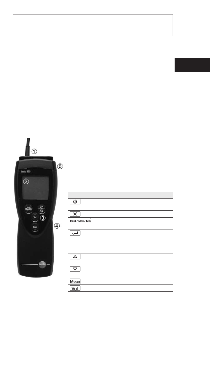
Overview
Probe
Display
Control buttons
Battery compartment (rear)
Service compartment (rear)
Button functions
Button Functions
Switch instrument on;
switch instrument off (press and hold)
Switch display light on / off
Keep reading, display
maximum/minimum value
Open/leave configuration mode (press
and hold);
In configuration mode:
Confirm input
In configuration mode:
Increase value, select option
In configuration mode:
Reduce value, select option
Multi-point and timed mean calculation
Volumetric flow
de
enfresitptsvnl????
Page 6

3. Production description22
Important displays
Display Meaning
Battery capacity (bottom right in display):
· 4 segments in the battery symbol are lit: Instrument battery is fully
charged
· No segments in the battery symbol are lit: Battery is almost spent
3.2 Voltage supply
Voltage is supplied by means of a 9V monobloc battery
(included in delivery) or rechargeable battery. It is not
possible to run the instrument from the mains supply or
charge a rechargeable battery in the instrument.
Page 7

4. Commissioning 23
4. Commissioning
This chapter describes the steps required to commission
the product.
²
Removing tthe pprotective ffilm oon tthe ddisplay:
i Pull the protective film off carefully.
²
Inserting aa bbattery/rechargeable bbattery:
1 To open the battery compartment on the rear of the
instrument, push the lid of the battery compartment in
the direction of the arrow and remove it.
2 Insert a battery/rechargeable battery (9V monobloc).
Observe the polarity!
3 To close the battery compartment, replace the lid of
the battery compartment in position and push it
against the direction of the arrow.
- The instrument switches itself on.
de
enfresitptsvnl????
Test Equipment Depot - 800.517.8431
99 Washington Street Melrose,
TestEquipmentDepot.com
MA 02176
Page 8

5. Operation24
5. Operation
This chapter describes the steps that have to be executed
frequently when using the product.
5.1 Connecting a probe
The necessary probes are permanently connected or
integrated. It is not possible to connect any additional
probes.
5.2 Switching the instrument
on / off
²
Switching tthe iinstrument oon:
i Press .
- The thermal sensor is heated up (5s).
- Measurement view is opened: The current reading
is displayed, or ----- lights up if no reading is
available.
²
Switching tthe iinstrument ooff:
i Press and hold (for approx. 2s) until the display
goes out.
5.3 Switching the display
light on / off
²
Switching tthe ddisplay llight oon/off:
The instrument is switched on.
i Press .
Page 9

5. Operation 25
5.4 Performing settings
1
To oopen cconfiguration mmode:
The instrument is switched on and is in measurement
view. Hold, Max or Min are not activated.
i Press and hold (for approx. 2s) until the display
changes.
- The instrument is now in configuration mode.
You can change to the next function with .
You can leave configuration mode at any time. To do
so, press and hold (for approx. 2s) until the
instrument has changed to measurement view. Any
changes that have already been made in configuration
mode will be saved.
2
To sset tthe aarea:
Configuration mode is opened, m
2
or in2is flashing.
i Set the cross-sectional area with / and
confirm with .
3
To sset tthe aabsolute ppressure:
The absolute pressure is required for the pressure
compensation of the flow velocity measurement value.
The absolute pressure must be measured using a
separate instrument or obtained from the local
weather station.
Configuration mode is opened, HPA or InHG is lit.
i Set the absolute pressure with / and confirm
with .
de
enfresitptsvnl????
Test Equip
99 Washington Street Melrose,
ment Depot - 800.517.8431
MA 02176
TestEquipmentDepot.com
Page 10

5. Operation26
4
To sset AAuto OOff:
Configuration mode is opened, AutoOff is flashing.
i Select the desired option with / and confirm
with :
· on: The measuring instrument switches off
automatically if no button is pressed for 10min (Hold
or Auto Hold is lit).
· oFF: The measuring instrument does not switch
itself off automatically.
5
To sset tthe uunit oof mmeasurement:
Configuration mode is opened, UNIT is lit.
i Select the desired unit of measurement with /
and confirm with .
6
To rreset:
Configuration mode is opened, RESET is lit.
i Select the desired option with / and confirm
with :
· no: Instrument is not reset.
·Yes: Instrument is reset. The instrument is reset to
the factory settings.
- The instrument returns to measurement view.
Page 11
6. Measuring 27
6. Measuring
This chapter describes the steps that are required to
perform measurements with the product.
²
Taking aa mmeasurement:
The instrument is switched on and is in measurement
view.
i Put the probe in position and read off the readings.
²
Changing tthe mmeasurement cchannel ddisplay:
i To change between displaying the temperature (°C)
and the calculated volumetric flow rate (m
3
/h):
Press .
²
Holding tthe rreading, ddisplaying tthe mmaximum/minimum
value:
The current reading can be recorded. The maximum and
minimum values (since the instrument was last switched
on) can be displayed.
i Press several times until the desired value is
displayed.
- The following are displayed in turn:
· Hold: the recorded reading
· Max: Maximum value
· Min: Minimum value
· The current reading
²
Resetting tthe mmaximum/minimum vvalues:
The maximum/minimum values of all channels can be
reset to the current reading.
1 Press several times until Max or Min lights up.
2 Press and hold (approx. 2s).
- All maximum or minimum values are reset to the
current reading.
de
enfresitptsvnl????
Page 12
6. Measuring28
²
Performing aa mmulti-ppoint mmean ccalculation:
Hold, Max or Min are not activated.
1 Press .
- Mean is lit.
- The number of readings recorded is displayed in
the upper line, while the current reading is
displayed in the lower line.
Option:
i To change between displaying the temperature (°C),
flow velocity (m/s) and calculated volumetric flow
rate (m
3
/h): Press .
2 To include readings (in the desired quantity):
Press (several times).
3 To end measurement and calculate the mean value:
Press .
- Mean flashes. The calculated spot mean value is
displayed.
4 To return to measurement view: Press .
²
Performing aa mmean ccalculation iin ttime:
Hold, Max or Min are not activated.
1 Press twice.
- Mean is lit.
- The elapsed measuring time (mm:ss) is displayed in
the upper line, while the current reading is
displayed in the lower line.
Option:
i To change between displaying the temperature (°C),
flow velocity (m/s), and calculated volumetric flow
rate (m
3
/h): Press .
2 To start measurement: Press .
3 To interrupt/continue measurement: Press each
time.
4 To end measurement and calculate the mean value:
Press .
- Mean flashes. The calculated mean value in time
is displayed.
5 To return to measurement view: Press .
Page 13

7. Care and maintenance 29
7. Care and maintenance
This chapter describes the steps that help to maintain the
functionality of the product and extend its service life.
±
Cleaning tthe hhousing:
i Clean the housing with a moist cloth (soap suds) if it
is dirty. Do not use aggressive cleaning agents or
solvents!
±
Changing tthe bbattery/rechargeable bbattery:
The instrument is switched off.
1 To open the battery compartment on the rear of the
instrument, push the lid of the battery compartment in
the direction of the arrow and remove it.
2 Remove the spent battery/rechargeable battery and
insert a new battery/rechargeable battery
(9 V monobloc). Observe the polarity!
3 To close the battery compartment, replace the lid of
the battery compartment in position and push it
against the direction of the arrow.
de
enfresitptsvnl????
Page 14

8. Questions and answers30
8. Questions and answers
This chapter gives answers to frequently asked questions.
Question Possible causes Possible solution
is lit (bottom right · Instrument battery is · Replace instrument
in display). almost spent. battery.
Instrument switches ·
Auto Off function · Switch function off.
itself off automatically. is switched on.
· Residual capacity · Replace battery.
of battery is too low.
Display:
----- · Probe is not plugged in. · Switch instrument off,
connect probe and
switch instrument
back on again.
· Probe break. · Please contact your
dealer or Testo
Customer Service.
Display reacts slowly · Ambient temperature · Raise ambient
is very low. temperature.
Display:
uuuuu · Permitted measuring · Keep to permitted
range was undershot. measuring range.
Display:
ooooo · Permitted measuring · Keep to permitted
range was exceeded. measuring range.
Test Equipment Depot - 800.517.8431
99 Washington Street Melrose,
MA 02176
TestEquipmentDepot.com
Page 15

9. Technical data 31
9. Technical data
Characteristic Value
Parameters Flow velocity (m/s)
Temperature (°C/°F)
Measuring range 0...+20 m/s
-20...+70°C/ -4...+158°F
Resolution 0.01 m/s
0.1°C / 0.1°F
Accuracy ±0.03m/s+5% of reading
±0.5°C/ ±0.9°F (0...+60.0°C/+32...+140 °F)
±0.7°C/ ±1.3°F (rest of range)
Probe Telescopic flow velocity/temperature probe (hot wire probe)
with NTC temperature sensor (permanently connected)
Measuring rate 2/s
Operating temperature range -20...+50°C / -4...+122 °F
Storage temperature -40...+85°C / -40...+185 °F
Voltage supply 1x 9V monobloc battery/rech. battery
Battery life approx. 20h
Protection class with TopSafe (accessory part): IP65
EC Directive 89/336/EEC
Warranty 2 years
10. Accessories/spare
parts
Name Part no.
TopSafe testo 425, protects from impact and dirt particles 0516 0221
de
enfresitptsvnl????
Page 16
32
99 Washington Street
Melrose, MA 02176
Phone 781-665-1400
Toll Free 1-800-517-8431
Visit us at www.TestEquipmentDepot.com
 Loading...