

Page 1
99 Washington Street
Melrose, MA 02176
Phone 781-665-1400
Toll Free 1-800-517-8431
Visit us at www.TestEquipmentDepot.com
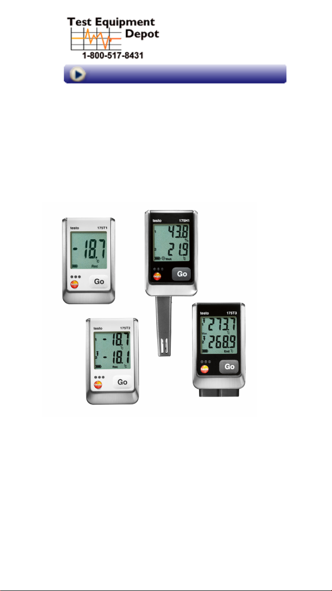
Instruction manual
testo 175 · Data loggers
Page 2

1 Contents
1 Contents
1 Contents 3
2 Safety and the environment 4
2.1. About this document 4
2.2. Ensure safety 5
2.3. Protecting the environment 5
3 Specifications 6
3.1. Use 6
3.2. Technical data 6
4 First steps 12
4.1. Unlock the data logger 12
4.2. Inserting batteries 13
4.3. Connecting the data logger to PC 13
5 Display and control elements 14
5.1. Display 14
5.2. LED 17
5.3. Key functions 18
6 Using the product 19
6.1. Connecting a sensor 19
6.2. Programming data logger 19
6.3. Menu overview 20
6.4. Mounting the wall bracket 23
6.5. Securing the data logger 24
6.6. Reading out measurement data 24
7 Maintaining the product 25
7.1. Changing batteries 25
7.2. Cleaning the instrument 27
8 Tips and assistance 27
8.1. Questions and answers 27
8.2. Accessories and spare parts 28
3
Page 3
2 Safety and the environment
2 Safety and the environment
2.1. About this document
Use
> Please read this documentation through carefully and
familiarize yourself with the product before putting it to
use. Pay particular attention to the safety instructions
and warning advice in order to prevent injuries and
damage to the products.
> Keep this document to hand so that you can refer to it
when necessary.
> Hand this documentation on to any subsequent users
of the product.
Symbols and writing standards
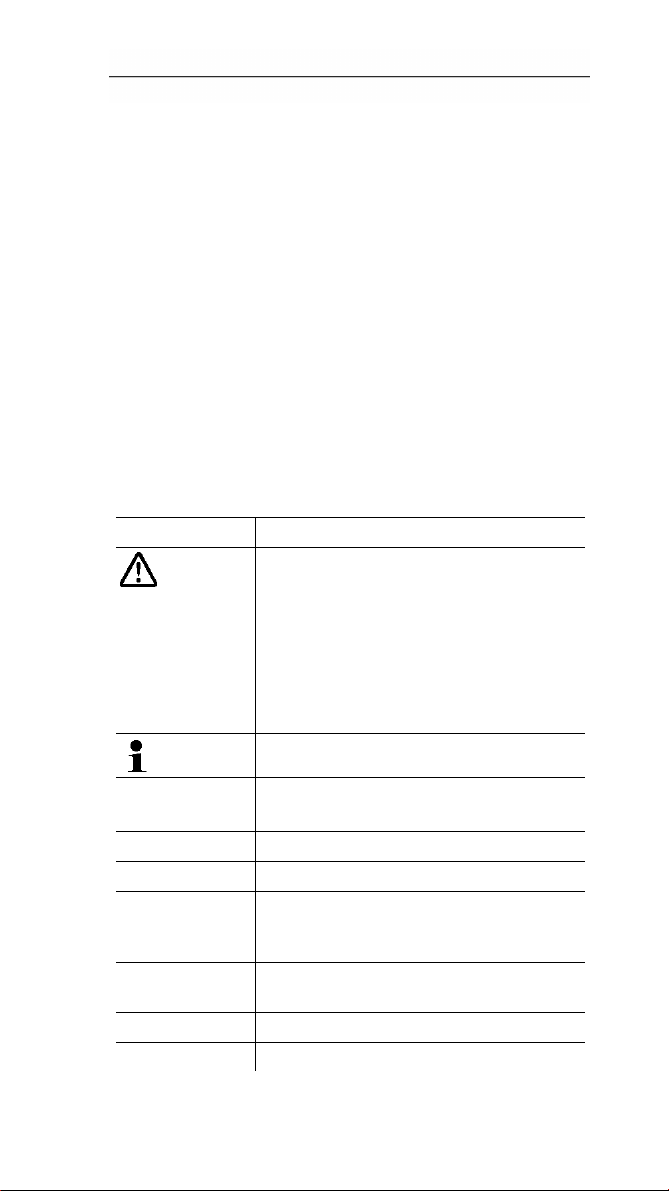
Representation Explanation
arning advice, risk level according to
W
the signal word:
Warning! Serious physical injury may
occur.
Caution! Slight physical injury or
damage to the equipment may occur.
> Implement the specified
precautionary measures.
Note: Basic or further information.
1. ...
2. ...
> ... Action: a step or an optional step.
- ... Result of an action.
Menu Elements of the instrument, the
[OK] Control keys of the instrument or buttons
... | ... Functions/paths within a menu.
“...” Example entries
4
Action: more steps, the sequence must
be followed.
instrument display or the program
interface.
of the program interface.
Page 4

2 Safety and the environment
2.2. Ensure safety
> Only operate the product properly, for its intended
purpose and within the parameters specified in the
technical data. Do not use any force.
> Never use the instrument to measure on or near live
parts.
> Before each measurement check that the connections
are correctl
appropriate sensors have been correctly plugged in.
The protection class in the technical data specified for
the corresponding instrument may otherwise not be
reached.
> testo 175 T3 : The maximum permissible difference in
potential between the sensor inputs is 50 V. Take this
into account when using surface sensors with nonisolated thermocouple.
> After the final measurement, allow probes and probe
shafts to cool down sufficiently in order to avoid burns
from the hot sensor tip or the probe shaft.
> Temperatures given on probes/sensors relate only to
the measur
handles and feed lines to any temperatures in excess
of 70 °C unless they are expressly permitted for higher
temperatures.
> Carry out only the maintenance and repair work on this
instrume
Follow the prescribed steps exactly. Use only original
spare parts from Testo.
y closed with blanking plugs or that
ing range of the sensors. Do not expose
nt that is described in the documentation.
2.3. Protecting the environment
> Dispose of faulty rechargeable batteries/spent batteries
in accordance with the valid legal specifications.
> At the end of its useful life, send the product to the
separate collection for electric and electronic devices
(observe local regulations) or return the product to
Testo for disposal.
5
Page 5

3 Specifications
3 Specifications
3.1. Use
Data loggers testo 175 are used to store and to read out
individual readings and measurement series.
With testo 175 measurement values are measured, saved
and transmitted to the PC via USB cable or SD card,
where they can be read out and analysed with the software
testo Comfort Software. With the software the data loggers
can also be individually programmed.
Typical applications
testo 175 T1 and testo 175 T2 are optimally suitable for
temperature measurements in refrigerators, freezers, coldstorage rooms and cooling shelves.
testo 175 T3 records two temperatures at the same time
and is most suitable e.g. for monitoring the temperature
spreading between feed and return flow in a heating
system.
testo 175 H1 controls the climatic conditions e.g. in
warehouses, offices and in the production area.
3.2. Technical data
testo 175 T1 (0572 1751)
Feature Values
Measurement
parameter
Sensor type NTC temperature sensor internal
Measurement
range
System accuracy ±0.5 °C (-35 to +55 °C) ± 1 digit
Resolution 0.1 °C
Operating
temperature
Storage
temperature
6
Temperature (°C/°F)
-35 to +55 °C
-35 to +55 °C
-35 to +55 °C
Page 6

3 Specifications
Feature Values
Measurement
Temperature (°C/°F)
parameter
Battery type
3x battery type AAA or Energizer L92
AAA-size cells
Life
3 years (15 min. measuring cycle,
+25 °C)
Degree of
IP 65
protection
Dimensions in
89 x 53 x 27 mm
mm (LxWxH)
Weight 130g
Housing ABS/PC
Measuring cycle 10s - 24h (freely selectable)
Interface Mini-USB, SD card slot
Memory capacity 1 million readings
Warranty 24 months, warranty conditions: see
website www.testo.com/warranty
EC Directive 2004/108/EC, complies with the EN
standard12830
1
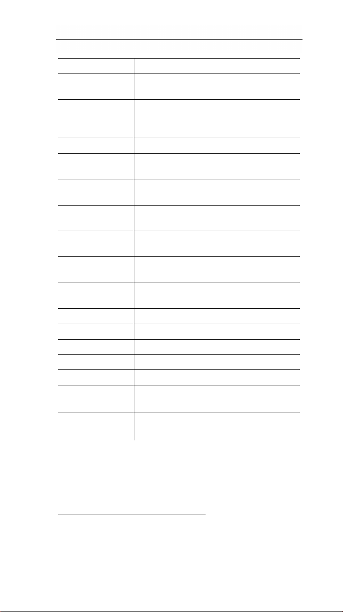
testo 175 T2 (0572 1752)
Feature Values
Measurement
Temperature (°C/°F)
parameter
Sensor type
NTC temperature sensor internal and
external
Measurement
range
1
Please note that, according to EN 12830, this instrument
-35 to +55 °C internal
-40 to +120 °C external
must be regularly checked and calibrated as specified in
EN 13486 (recommendation: every year) Contact us for
more information.
7
Page 7
3 Specifications
Feature Values
Measurement
Temperature (°C/°F)
parameter
System accuracy
Instrument
±0.5 °C (-35 to +55 °C) ± 1 digit
±0.3 °C (-40 to +120 °C) ± 1 digit
accuracy
Resolution 0.1 °C
Operating
-35 to +55 °C
temperature
Storage
-35 to +55 °C
temperature
Battery type
3x battery type AAA or Energizer L92
AAA-size cells
Life
3 years (15 min. measuring cycle,
+25 °C)
Degree of
IP 65
protection
Dimensions in
89 x 53 x 27 mm
mm (LxWxH)
Weight 130g
Housing ABS/PC
Measuring cycle 10s - 24h (freely selectable)
Interface Mini-USB, SD card slot
Memory capacity 1 million readings
Warranty 24 moths, warranty conditions: see
website www.testo.com/warranty
EC Directive 2004/108/EC, complies with the EN
standard12830
2
2
Please note that, according to EN 12830, this instrument
must be regularly checked and calibrated as specified in
EN 13486 (recommendation: every year) Contact us for
more information.
8
Page 8
3 Specifications
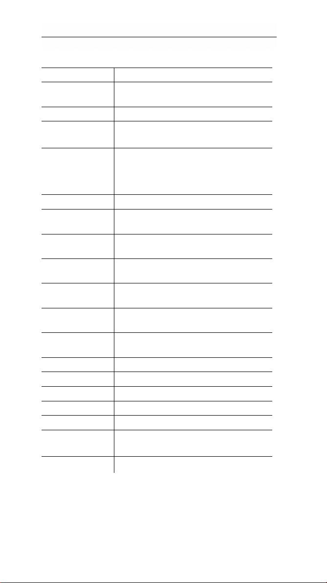
testo 175 T3 (0572 1753)
Feature Values
Measurement
parameter
Sensor type 2 thermocouples (type K or T) external
Measurement
range
Instrument
accuracy
Resolution 0.1 °C
Operating
temperature
Storage
temperature
Battery type
Life
Degree of
protection
Dimensions in
mm (LxWxH)
Weight 130g
Housing ABS/PC
Measuring cycle 10s - 24h (freely selectable)
Interface Mini-USB, SD card slot
Memory capacity 1 million readings
Warranty 24 months, warranty conditions: see
EC Directive 2004/108/EC
Temperature (°C/°F)
-50 to +400 °C (type T)
-50 to +1000 °C (type K)
±0.5 °C (-50 to +70 °C) ± 1 digit
± 0.7% of the measurement value
(+70.1 to +1000 °C)
± 1 digit
-20 to +55 °C
-20 to +55 °C
3x battery type AAA or Energizer L92
AAA-size cells
3 years (15 min. measuring cycle,
+25 °C)
IP 65
89 x 53 x 27 mm
website www.testo.com/warranty
9
Page 9

3 Specifications
testo 175 H1 (0572 1754)
Feature Values
Measurement
parameter
Sensor type
Temperature (°C/°F), moisture (%rF
/%RH/ °Ctd/ g/m
NTC temperature sensor, capacitive
humidity sensor
Number of
2x internal (stubs)
measuring
channels
Measuring
ranges
-20 to +55 °C
-40 to +50 °Ctd
0 to 100 %rF (not for condensing
atmosphere)
System
accuracy
4
±2%rF (2 to 98%rF) at 25 °C
±0.03 %rF/K ± 1 digit
±0.4 °C (-20 to +55 °C) ± 1 digit
Long-term drift of
the sensor under
<1 %RH/year (ambient temperature
+25 °C)
normal
conditions
Usage conditions
All specifications call for an
atmosphere with a percentage of
harmful gases that does not exceed the
maximum allowable concentration
(MAC). A higher percentage of harmful
gases (e.g. ammonia or hydrogen
peroxide) may result in damage to the
sensor.
Resolution 0.1 %rF, 0.1 °C
Operating
-20 to +55 °C
temperature
Storage
-20 to +55 °C
temperature
Battery type
3x battery type AAA or Energizer L92
AAA-size cells
3
)
3
3
Long-term condensation in the system may result in
damage to the measuring instrument.
4
The use of sintered caps may affect the response time of
the sensor.
10
Page 10

3 Specifications
Feature Values
Measurement
parameter
Life
Temperature (°C/°F), moisture (%rF
/%RH/ °Ctd/ g/m
3
)
3 years (15 min. measuring cycle,
+25 °C)
Degree of
IP 54
protection
Dimensions in
149 x 53 x 27 mm
mm (LxWxH)
Weight 130g
Housing ABS/PC
Measuring cycle 10s - 24h (freely selectable)
Interface Mini-USB, SD card slot
Memory capacity 1 million readings
Warranty 24 months, warranty conditions: see
website www.testo.com/warranty
EC Directive 2004/108/EC
Battery life
The programming windows of the software provide you
with typical guide values for the expected lifetime of the
battery. This lifetime is calculated on the basis of the
following factors:
• Measuring cycle
• Number of connected sensors
Since the battery life depends on quite a few other factors,
the calculated data can only serve as guide values.
The following factors have a negative effect on the battery
life:
• longer flashing of the LEDs
• frequent reading out (several times per day) via the
SD-card
• extreme fluctuations in operating temperature
The following factors have a positive effect on the battery
life:
• display switched off
The battery capacity reading in the display of the data
logger is based on the calculated values. However, the
11
Page 11
4 First steps
data logger is switched off when a critical voltage level has
been reached. It may therefore happen that:
• readings are still recorded, even though the battery
capacity reading says "empty".
• the measurement program is stopped, even though the
battery capacity reading just before indicated a still
remaining battery capacity.
In case of an empty battery or a battery change saved
readings will not be lost.
4 First steps
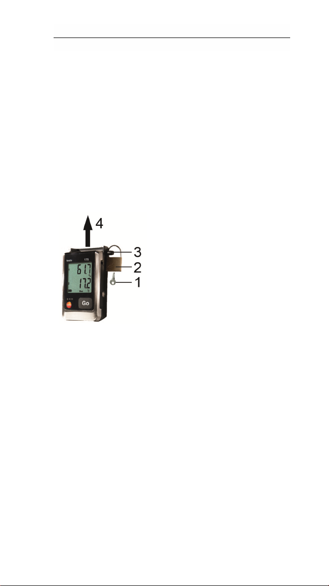
4.1. Unlock the data logger
1. Open the lock with the key (1).
2. Remove the lock (2) from the locking pin.
3. Pull the locking pin (3) out of the holes in the wall
bracket.
4. Slide the data logger out of the wall bracket (4).
12
Page 12
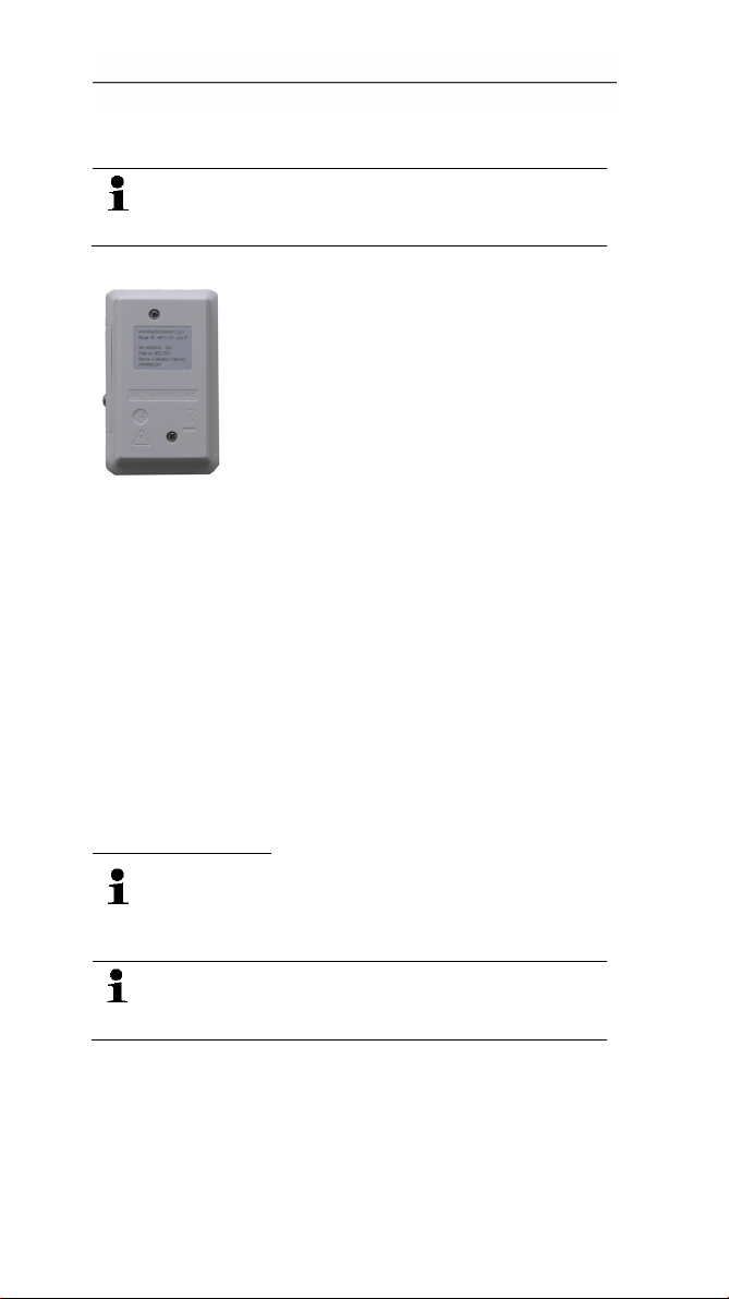
4.2. Inserting batteries
4 First steps
In order to reac
temperatures below -10 °C you should use
Energizer L92 AAA-size cells.
1. Place the data logger on its front.
2. Loosen the screws on the back of the data logger.
3. Remove the battery compartment cover.
4. Insert the batteries (type AAA). Observe the polarity!
5. Place the battery compartment cover on the battery
compartment.
6. Tighten the screws.
- The display shows rST.
h the battery life under application
4.3. Connecting the data logger to
PC
For
testo Comfort Software Basic 5:
The software is available in the Internet as a free download
equiring registration
r
The instructions for the installation and operation
of the software can be found in the testo Comfort
Software Basic 5 instruction manual, which can be
downloaded together with the software.
T
he software can be ordered on CD (article-no:
0572 0580), if the download from the Internet is
not desired.
For testo Comfort Software Professional und testo Comfort
Software CFR:
> Insert the CD into the CD-ROM drive.
1. Install the software testo Comfort Software.
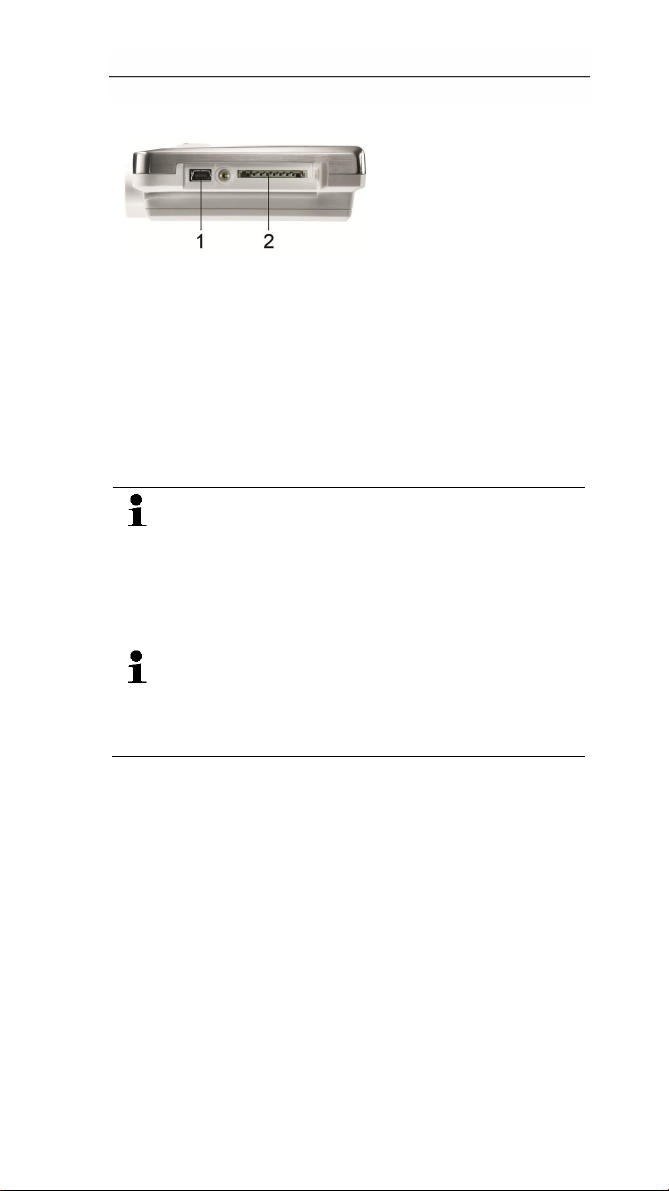
2. Connect the USB cable to a free USB port on the PC.
3. Loosen the screw on the right side of the data logger.
13
Page 13
5 Display and control elements
4. Open the cover.
5. Plug the USB cable into the Mini USB port (1).
6. Confi
gure the data logger, see separate operating
instructions testo Comfort Software.
5 Display and control
elements
5.1. Display
he display function can be switched on/off via the
T
software testo Comfort Software.
Depending on the operating status, various
information may be shown in the display. A
detailed representation of the information that can
be called up can be found under Menu overview
page 20.
or technical reasons the display speed of liquid
F
crystal displays becomes slower at temperatures
below 0 °C (approx. 2 seconds at -10 °C, approx.
6 seconds at -20 °C). This has no influence on the
measuring accuracy.
14
Page 14
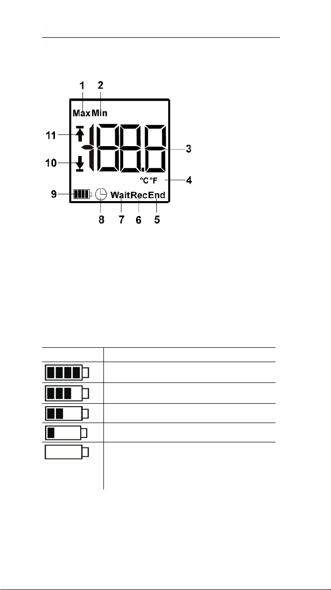
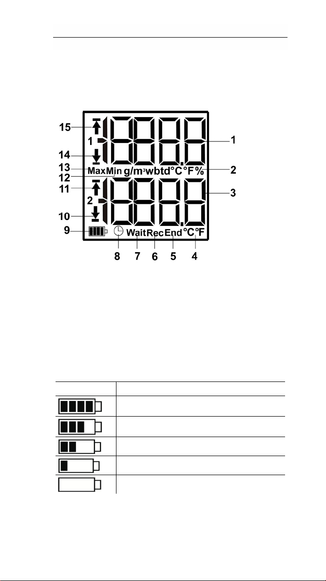
testo 175 T1
5 Display and control elements
1 High
2 Lowest saved reading
3 Reading
4 Units
5 Measurement program over
6 Measurement program running
7 Wait for start of measurement program
8 Start criterion Date/ Time programmed
9 Battery capacity
10 Lower alarm value
est saved reading
Icon Capacity
>151 days
<150 days
<90 days
<60 days
<30 days
> Read out data and change battery
(see Reading out
page 24).
• Flashes: programmed alarm value is shown
• Lights: programmed alarm values were fallen short
of
measurement data
15
Page 15
5 Display and control elements
11 Upper alarm value
• Flashes: programmed alarm value is shown
• Lights: programmed alarm values were exceeded
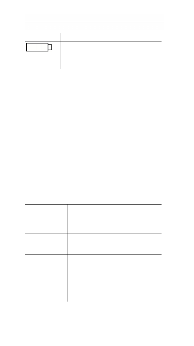
testo 175 T2, testo 175 T3, testo 175 H1
1 R
eading channel 1
2 Units channel 1
3 Reading channel 2
4 Units channel 2
5 Measurement program over
6 Measurement program running
7 Wait for start of measurement program
8 Start criterion Date/ Time programmed
9 Battery capacity
Icon Capacity
>151 days
16
<150 days
<90 days
<60 days
<30 days
Page 16
5 Display and control elements
Icon Capacity
30 days
<
> Read out data and change battery
(see Reading out
page 24).
10 Lower limit value channel 2:
• Flashes: programmed alarm value is shown
• Lights: programmed alarm values were fallen short
of
11 Upper limit value channel 2:
• Flashes: programmed alarm value is shown
• Lights: programmed alarm values were exceeded
12 Lowest saved reading
13 Highest saved reading
14 Lower limit value channel 1:
• Flashes: programmed alarm value is shown
• Lights: programmed alarm values were fallen short
of
15 Upper limit value channel 1:
• Flashes: programmed alarm value is shown
• Lights: programmed alarm values were exceeded
measurement data
5.2. LED
Representation Explanation
Red LED flashes
once every 10
seconds
Red LED flashes
twice every 10
seconds
Red LED flashes
three times every
10 seconds
Red LED flashes
three times when
pressing the
button
Remaining battery capacity has
dropped below 30 days
Remaining battery capacity has
dropped below 10 days
Battery is empty:
Limiting value was exceeded/fallen
short of
17
Page 17

5 Display and control elements
Representation Explanation
Yellow LED
flashes three
times
Yellow LED
flashes three
times when
pressing the
button
Green and
yellow LED flash
three times when
pressing the
button.
Green LED
flashes three
times when
pressing the
button
Green LED
flashes five times
when pressing
the button
Green, yellow
and red LED
flash in
succession
Instrument changes from Wait-mode to
Rec-mode.
Instrument is in Rec-mode
Instrument is in End-mode
Instrument is in Wait-mode
Long pressing of the GO button has set
a time mark.
The battery has been changed.
5.3. Key functions
A detailed representation of the display readings can be
found under Menu overview page 20.
✓ Instrument in operating status Wait and start criterion
Button start programmed.
> Press [GO] for approx. 3 seconds to start the
measurement program.
- The measurement program starts and Rec appears in
the display.
✓ Instrument is in operating status Wait:
> Press [GO] in order to change between displays of
upper alarm value, lower alarm value, battery life and
last reading.
18
Page 18

6 Using the product
The displays appear in the specified sequence.
✓ Instrument is in operating status Rec or End:
> Press [GO] in order to change between displays of
highest saved reading, lowest saved reading, upper
alarm value, lower alarm value, battery life and last
reading.
The displays appear in the specified sequence.
6 Using the product
6.1. Connecting a sensor
Observe the following points when connecting sensors to
data logger and measuring points.
> Ensure correct polarity of the plugs.
> Press the plugs firmly into the ports to ensure leak
tightness. However, do not apply force!
> Make sure that the plugs are firmly connected to the
data logger or that the connections are closed with
blanking plugs.
> Ensure correct positioning of the sensor to avoid
disturbing influences affecting the measurement.
> testo 175 T3: Always make sure that you connect the
sensor configured (via the software testo Comfort
Software) to the individual sockets. The numbers of the
connections are printed on the housing.
6.
2. Programming data logger
In order to adapt the programming of your data logger to
your individual requirements, you require the testo Comfort
Software Basic 5 software. It is available in the Internet as
a free download r
The instructions for the installation and operation
of the software can be found in the testo Comfort
Software Basic 5 instruction manual that is
downloaded together with the software.
equiring registration
19
Page 19

6 Using the product
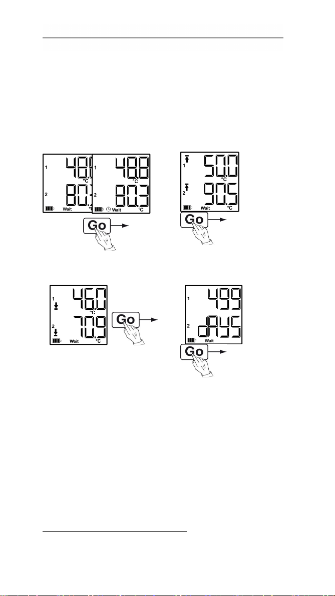
6.3. Menu overview
T
he menu overview shows exemplary display
representations of the data logger testo 175-T2.
The display must be switched on to be able to
show the corresponding indications. This is
accomplished with the software testo Comfort
Software.
The indication in the display is updated according
to the programmed measurement rate. Only
readings from active channels are displayed.
The channels are also activated via the software
testo Comfort Software.
The symbols for upper or lower alarm value light
up in operating states Rec and End, if the
programmed alarm value has been exceeded or
fallen short off.
After 10 seconds without operating a key the
display will return to its initial state.
20
Page 20
6 Using the product
Wait mode: Start criterion is programmed, but not yet
fulfilled.
① Last
reading
Start criterion
key start / PC
start
5
Start criterion
Date/Time
② Upper alarm value
③ Lower alarm value ④ Battery capacity in
days
5
Last reading
(see Fig. ① Wait
mode)
5
Measurement value is not saved
21
Page 21
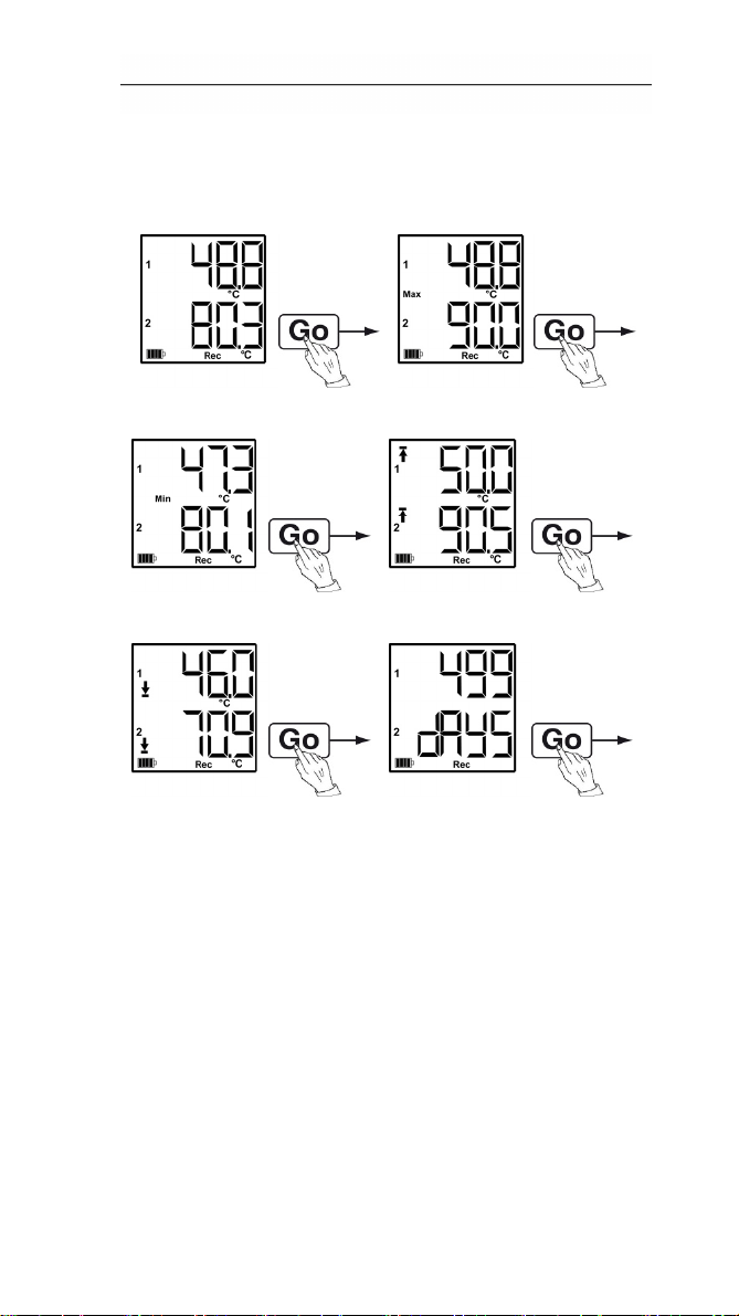
6 Using the product
Rec mode: Start criterion was fulfilled, data logger saves
readings
① Last reading ② Highest reading
③ Lowest reading ④ Upper alarm value
⑤ Lower alarm value ⑥ Battery capacity in days
Last reading (see Fig. ① Rec mode)
22
Page 22
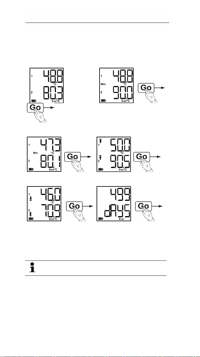
6 Using the product
End mode: Measurement program finished (stop criterion
reached – memory full or number of readings) depending
on programming
① Last reading ② Highest reading
③ Lowest reading ④ Upper alarm value
⑤ Lower alarm value ⑥ Battery capacity in days
Last reading (see Fig. ① End mode)
6.4. Mounting the wall bracket
The scope of delivery does not include mounting
materials (e.g. screws, wall plugs).
✓ The data logger has been removed from the wall
bracket.
1. Position the wall bracket at the desired place.
2. Use a pen or something similar to mark the location for
the fastening screws.
3. Prepare the fastening location in accordance with the
fastening material (e.g. drill hole, insert wall plugs).
23
Page 23
6 Using the product
4. Fasten the wall bracket with suitable screws.
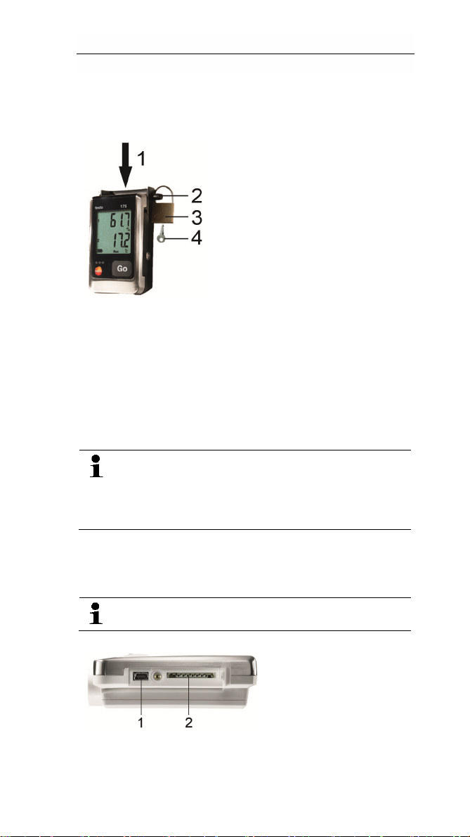
6.5. Securing the data logger
✓ The wall bracket has been mounted.
1. Slide the data logger into the wall bracket (1).
2. Push the locking pin (2) through the holes in the wall
bracket.
3. Fasten the lock (3) on the locking pin.
4. Pull off the key (4).
6.6. Reading out measurement data
The measurement data remain stored in the data
logger after they have been read out and can
therefore be read out several times. The
measurement data will only be deleted when the
data logger is reprogrammed.
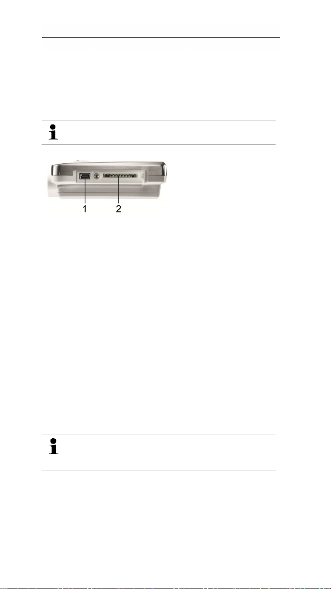
Via USB cable
1. Connect the USB cable to a free USB port on the PC.
2. Loosen the screw on the right side of the data logger.
Use a coin for this purpose.
3. Open the cover.
4. Plug the USB c
24
able into the Mini USB port (1).
Page 24
7 Maintaining the product
5. Read out the data logger and process the read out
data, see separate operating instructions testo Comfort
Software.
Via SD card
1. Loosen the screw on the right side of the data logger.
Use a coin for this purpose.
2. Open the cover.
3. Push the SD card into
- The display shows Sd (testo 175 T1) or Sd CArd (testo
175 T2, testo 175 T3, testo 175 H1).
4. Hold [Go] depressed for longer than 2 seconds.
- The display shows CPY (testo 175 T1) or COPY (testo
175 T2, testo 175 T3, testo 175 H1).
- The yellow LED lights during the copying process.
- The green LED flashes twice and after the copying
process the display shows OUT.
5. Remove the SD card.
6. Insert the SD card into the SD card slot on the PC.
7. Process the read out data, see separate operating
instructions testo Comfort Software.
7 Maintaining the product
the SD card slot (2).
7.1. Changing batteries
The battery change stops the currently running
measurement program. However, stored
measurement data are preserved.
1. Read out stored measurement data, see Reading out
measurement data page 24.
✓ If it is no longer
measurement data because the battery capacity is too
low:
possible to read out the saved
25
Page 25
7 Maintaining the product
> Change the batteries and read out the stored
measurement data after.
2. Place the data logger on its front.
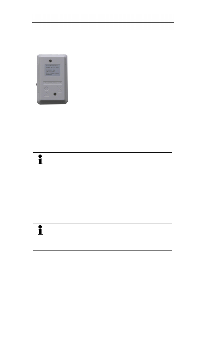
3. Loos
4. Remove the battery compartment cover.
5. T
6. Insert three new batteries (type AAA). Observe the
7. Place the battery compartment cover on the battery
8. Tighten the screws.
- The display shows rST.
9. Connect the data logger to the PC with a USB cable.
10. Start the software testo Comfort Software and set up a
11. Reconfigure the data logger or load the old, saved
- The data logger is once again ready for use.
en the screws on the back of the data logger.
ake the empty batteries out of the battery
compartment.
polarity!
Onl
y use new branded batteries. If a partially
exhausted battery is inserted, the calculation of the
battery capacity will not be performed correctly.
In order to reach the battery life under application
temperatures below -10 °C you should use
Energizer L92 AAA-size cells.
compartment.
T
he data logger needs to be reconfigured. For this
purpose the software testo Comfort Software must
be installed on the computer and a connection to
the data logger must be set up.
connection to the data logger.
configuration, see separate operating instructions testo
Comfort Software.
26
Page 26
8 Tips and assistance
7.2. Cleaning the instrument
CAUTION
Damage to the sensor!
> Ensure that no liquid enters the inside of the housing.
> If the housing of the instrument is dirty, clean it with a
damp cloth.
Do not use any aggressive cleaning agents or solvents!
Weak household cleaning agents or soap suds can be
used.
8 Tips and assistance
8.1. Questions and answers
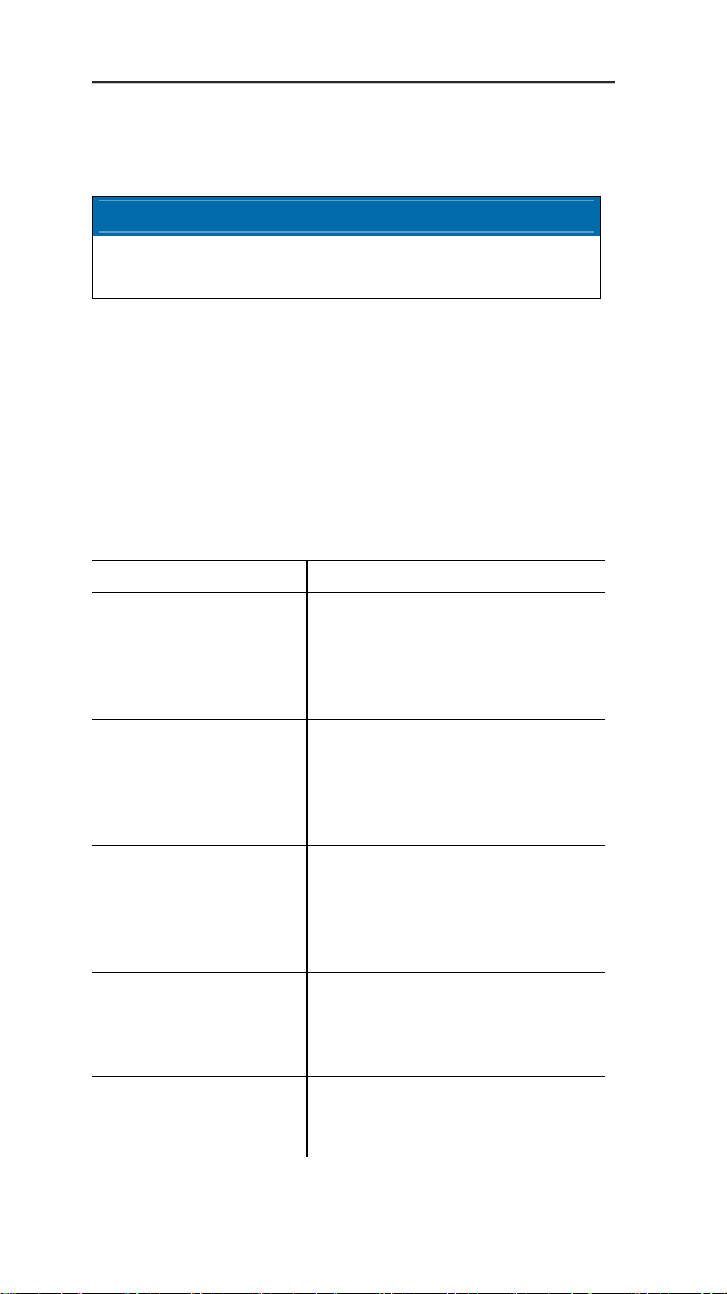
Question Possible causes / solution
FULL appears in the
display, the red LED
flashes twice, out
appears in the display.
Err appears in the
display, the red LED
flashes twice, out
appears in the display.
nO dAtA appears in
the display, the red
LED flashes twice.
rST appears in the
display.
- - - -
appears in the display.
Insufficient memory capacity on
SD card to save the data.
> Remove the SD card, free up
more memory space and
copy data.
An error occurred while saving
data to the SD card.
> Remove the SD card, free up
more memory space and
copy data.
The logger has not yet recorded
any data and is in Wait mode.
> Remove the SD card and
wait until the logger is in Rec
mode.
The battery was changed. No
data are recorded.
> Reprogram the data logger
via the software.
Sensor of data logger defective.
> Contact your dealer or the
Testo Customer Service.
27
Page 27
8 Tips and assistance
If you have any questions please contact your local dealer
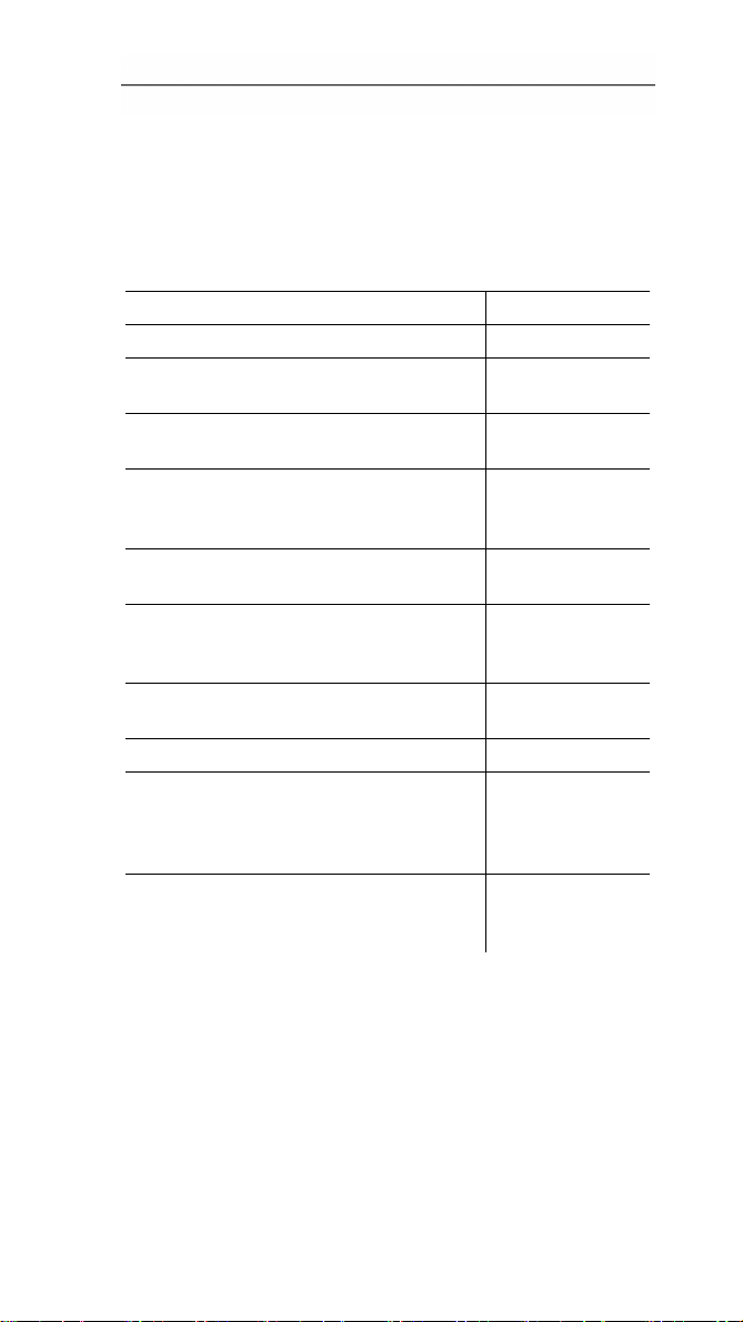
8.2. Accessories and spare parts
Description Article no.
Wall bracket (black) with lock 0554 1702
Mini USB cable to connect the data
logger testo 175 to the PC
SD card to read out the data logger
175
Batteries (alkaline-manganese AAAsize cells) for applications down to -10
°C
Batteries (Energizer L92 AAA-size
cells) for applications down to -10 °C
CD testo Comfort Software Basic 5 (if
free-of-charge, registered download
from website is not wanted)
CD testo Comfort Software
Professional
CD testo Comfort Software CFR 0554 1705
ISO moisture calibration certificate,
calibration points 11,3 %rF; 50,0 %rF;
75,3 %rF at +25°C/+77°F; per
channel/instrument
ISO temperature calibration certificate,
calibration points -18°C, 0°C, +40°C;
per channel/instrument
0449 0047
0554 8803
0515 0009
0515 0042
0572 0580
0554 1704
0520 0076
0520 0153
For further accessories and spare parts, please refer to the
product catalogues and brochures
Test Equipment Depot - 800.517.8431 - 99 Washington Street Melrose, MA 02176
28
TestEquipmentDepot.com
 Loading...