

TESTO Saveris T2D, Saveris T1, Saveris T1D, Saveris T2, Saveris T3 Commissioning Instructions
...Page 1
Pharma Solutions
Measurement data monitoring system:
testo Saveris
Software:
testo Saveris CFR 4.6 SP1
testo Saveris CFR transport add-on
Commissioning instructions
Page 2

Page 3

Contents
Contents
1 About this document ........................................................................... 7
1.1 Symbols and writing standards ............................................................................. 7
1.2 Warning notices .................................................................................................... 8
2 Safety and disposal .............................................................................. 8
2.1 Safety .................................................................................................................... 8
2.2 Batteries ................................................................................................................ 9
3 Protecting the environment ................................................................. 9
4 Support ................................................................................................. 9
5 Commissioning instructions ............................................................. 10
5.1 System requirements .......................................................................................... 10
5.1.1 Computer ................................................................................................................... 10
5.1.2 Operating system and database ................................................................................ 10
5.1.3 Network environment ................................................................................................. 12
5.1.3.1 WLAN-specific data ............................................................................................................. 12
5.1.3.2 Technical data for a secure WLAN ...................................................................................... 12
6 Commissioning .................................................................................. 13
6.1 Flowchart: Configuration for monitoring stationary zones ................................... 13
6.2 Flowchart (“Mobile monitoring”): Configuration for transport monitoring with
Saveris radio data loggers .................................................................................. 15
6.3 Commissioning the Saveris base ........................................................................ 17
6.3.1 Inserting SIM card (optional) ...................................................................................... 17
6.3.2 Connecting network cable to the Saveris base .......................................................... 18
6.3.3 Connecting GSM antenna (optional) .......................................................................... 19
6.4 Connecting Saveris base to power supply .......................................................... 19
6.4.1 Power supply via mains unit ....................................................................................... 19
6.4.2 Power supply via plug-in/screw connection (optional) ................................................ 20
6.4.3 Connecting USB cable (optional) ............................................................................... 21
6.4.4 Assigning an IP address to the Saveris base (optional) ............................................. 22
6.5 Commissioning of radio data loggers in testo Saveris ........................................ 23
6.5.1 Inserting batteries into Saveris radio data logger ....................................................... 23
6.5.2 Registering Saveris radio data loggers in the system ................................................ 24
Page 4

Contents
6.6 BT Gateway for testo 182 ................................................................................... 26
6.6.1 Equipment required .................................................................................................... 26
6.6.2 Establishing connections to the gateway .................................................................... 26
6.6.3 Configuring the BT Gateway for testo 182 .................................................................. 27
6.6.3.1 Configuring operation via WLAN ......................................................................................... 28
6.6.3.2 Configuring operation via Ethernet / LAN ............................................................................ 29
6.6.3.3 Configuring the AWS Bucket ............................................................................................... 29
6.6.4 Carrying out firmware updates ................................................................................... 30
6.7 Commissioning testo Saveris software ............................................................... 30
6.7.1 Installing testo Saveris software ................................................................................. 30
6.7.2 Installing Saveris mail services ................................................................................... 31
6.7.2.1 Installing MAPI mail ............................................................................................................. 31
6.7.2.2 Installing SMTP mail ........................................................................................................... 33
6.7.2.3 Installing testo Saveris CFR transport add-on ..................................................................... 34
6.8 Initial commissioning of the hardware ................................................................ 35
6.9 Configuring hardware ......................................................................................... 41
6.9.1 Integrating testo Saveris 2 H2 WLAN data logger ...................................................... 43
6.9.2 Integration of Ethernet data loggers into testo Saveris (optional) ............................... 45
6.9.2.1 Connecting network cable ................................................................................................... 45
6.9.2.2 Connecting testo Saveris Ethernet data logger to power supply (mains unit) ...................... 46
6.9.2.3 Connecting USB cable and installing driver (optional) ......................................................... 47
6.9.3 Integrating testo Saveris analog coupler (optional)..................................................... 48
6.9.4 Integrating testo Saveris transmitter ........................................................................... 52
6.9.5 Integrating testo Saveris router (optional) ................................................................... 52
6.9.5.1 Connecting testo Saveris router to power supply (mains unit) ............................................. 53
6.9.5.2 Connecting testo Saveris router to power supply (mains unit) ............................................. 53
6.9.5.3 Registering testo Saveris router .......................................................................................... 55
6.9.5.4 Assigning data loggers ........................................................................................................ 56
6.9.5.5 Connecting Saveris routers in series ................................................................................... 58
6.9.6 Integrating Saveris converter (optional) ...................................................................... 61
6.9.7 Integrating Saveris extender ....................................................................................... 61
6.9.8 Integrating Saveris cockpit unit (optional) ................................................................... 62
6.9.8.1 Registering Saveris cockpit unit .......................................................................................... 63
6.9.8.2 Fitting Saveris cockpit unit in the driver's cab and connecting it to a power supply .............. 65
Page 5

Contents
6.10 Installation of the components ............................................................................ 66
6.10.1 Mounting the Saveris base on the wall ....................................................................... 66
6.10.2 Setting up Saveris base with the stand ...................................................................... 67
6.10.3 Wall mounting of data loggers .................................................................................... 68
6.10.3.1 Wall mounting of T1/T1D/T2/T2D/Pt/PtD/H4D radio data loggers ....................................... 68
6.10.3.2 Wall mounting of testo Saveris 2 H2 WLAN data loggers .................................................... 70
6.10.3.3 BT Gateway for testo 182 wall mounting ............................................................................. 70
6.10.3.4 Removing components from the wall bracket ...................................................................... 72
6.10.4 Checking the measurement system again ................................................................. 72
6.11 Performing test run ............................................................................................. 73
6.11.1 Checking system availability ...................................................................................... 73
6.11.2 Performing system test ............................................................................................... 74
7 Maintenance ....................................................................................... 75
7.1 Data backup ........................................................................................................ 75
7.1.1 Creating backup ......................................................................................................... 75
7.1.1.1 Automatic backup of the Saveris data ................................................................................. 75
7.1.1.2 Manual backup of the Saveris data ..................................................................................... 75
7.1.2 testo Saveris base backup ......................................................................................... 76
7.1.3 Checking the database capacity ................................................................................ 77
7.2 System settings ................................................................................................... 77
7.3 Replacing components ....................................................................................... 80
7.3.1 Deleting components ................................................................................................. 80
7.3.2 Adding new components ............................................................................................ 81
7.3.3 Re-registering components ........................................................................................ 85
7.4 Calibration and adjustment ................................................................................. 86
7.4.1 On-site calibration and adjustment ............................................................................. 86
7.4.2 External calibration and adjustment ........................................................................... 86
7.5 Changing batteries .............................................................................................. 87
7.5.1 Changing the Saveris base batteries ......................................................................... 87
7.5.2 Changing the Saveris radio data logger batteries ...................................................... 88
7.5.2.1 Changing the Saveris Ethernet data logger / Saveris analog coupler batteries .................... 90
7.6 Update ................................................................................................................ 91
7.6.1 Carrying out software update ..................................................................................... 91
7.6.1.1 Uninstalling software ........................................................................................................... 92
7.6.1.2 Installing software ................................................................................................................ 92
7.6.1.3 Installing server ................................................................................................................... 92
7.6.2 Performing firmware system update ........................................................................... 93
7.6.3 Carrying out a testo Saveris cockpit unit firmware update.......................................... 95
Page 6

Contents
8 Technical data .................................................................................... 97
8.1 testo Saveris base .............................................................................................. 97
8.2 Radio data loggers for testo Saveris .................................................................. 98
8.2.1 General ....................................................................................................................... 98
8.2.2 testo Saveris T1 / T1D ................................................................................................ 98
8.2.3 testo Saveris T2 / T2D ................................................................................................ 99
8.2.4 testo Saveris T3 / T3D .............................................................................................. 100
8.2.5 testo Saveris Pt / PtD ............................................................................................... 100
8.2.6 testo Saveris H3 / H3D ............................................................................................. 101
8.2.7 testo Saveris H2D ..................................................................................................... 102
8.2.8 testo Saveris H4D ..................................................................................................... 102
8.2.9 testo Saveris 2 H2 .................................................................................................... 102
8.3 Ethernet data loggers for testo Saveris ............................................................ 104
8.3.1 General ..................................................................................................................... 104
8.3.2 testo Saveris PtE ...................................................................................................... 105
8.3.3 testo Saveris T1E ..................................................................................................... 105
8.3.4 testo Saveris H4E ..................................................................................................... 106
8.3.5 External probes ........................................................................................................ 106
8.3.6 testo Saveris T4E ..................................................................................................... 107
8.3.7 testo Saveris H2E ..................................................................................................... 107
8.3.8 testo Saveris H1E ..................................................................................................... 108
8.4 Analog couplers for testo Saveris ..................................................................... 109
8.4.1 Saveris wireless analog coupler U1 .......................................................................... 109
8.4.2 Saveris Ethernet analog coupler U1E ....................................................................... 110
8.5 Transport data loggers for testo Saveris .......................................................... 111
8.5.1 testo 182 – BT transport data logger ........................................................................ 111
8.5.2 testo 184 · USB Transport data logger ..................................................................... 111
8.6 testo Saveris router .......................................................................................... 113
8.7 testo Saveris converter ..................................................................................... 114
8.8 testo Saveris extender ...................................................................................... 114
8.9 BT Gateway for testo 182 ................................................................................. 115
8.10 testo Saveris cockpit unit .................................................................................. 116
Page 7
1 About this document
• …
Action: one step or optional step.
Requirement
Position numbers for the clarification of the relationship
Elements of the instrument, the instrument display or the
program interface.
Control keys of the instrument or buttons of the program
interface.
... | ...
Functions/paths within a menu.
1 About this document
• The instruction manual is an integral part of the testo Saveris measurement
data monitoring system.
• Keep this documentation to hand so that you can refer to it when necessary.
• Please read this instruction manual through carefully and familiarize yourself
with the product before putting it to use.
• Hand this instruction manual on to any subsequent users of the product.
• Pay particular attention to the safety instructions and warning advice in order
to prevent injury and damage to the product.
• Please read this instruction manual through carefully and familiarize yourself
with the product before putting it to use.
1.1 Symbols and writing standards
Display Explanation
Note: basic or further information.
1. ...
Action: several steps, the sequence must be followed.
2. ...
List
> ...
- ...
Result of an action.
✓ …
...
between text and picture.
...
Menu
[OK]
“...” Example entries
7
Page 8
2 Safety and disposal
Life
Indicates possible serious injuries.
Indicates possible minor injuries.
ATTENTION
Indicates possible damage to equipment.
At temperatures below 5°C, the (rechargeable) batteries will not charge;
1.2 Warning notices
Always pay attention to any information marked with the following warning
notices along with warning pictograms. Implement the specified precautionary
measures!
DANGER
-threatening danger!
WARNING
CAUTION
2 Safety and disposal
2.1 Safety
• Always operate the product properly, for its intended purpose and within the
parameters specified in the technical data. Do not use any force.
• Never use the Saveris probes to measure on or near live parts.
• Only carry out maintenance and repair work on the components of the testo
Saveris measurement data monitoring system that are described in the
documentation. Follow the prescribed steps exactly when doing the work.
Use only original spare parts from Testo.
• The use of the wireless module is subject to the regulations and stipulations
of the respective country of use and, in each case, the module may only be
used in countries for which a country certification has been granted. The
user and every owner undertake to adhere to these regulations and
prerequisites for use and acknowledge that the re-sale, export, import, etc. in
particular in, to or from countries without wireless permits, is their
responsibility.
• When selecting the mounting location, ensure that the permissible ambient
and storage temperatures are adhered to.
there is only a limited possibility of reliable system operation in this
temperature range.
8
Page 9

3 Protecting the environment
• Do not use the product if there are signs of damage to the housing.
• Do not commission the instrument if there are signs of damage on the
housing.
• Dangers may also arise from objects being measured or the measuring
environment. Always comply with the locally valid safety regulations when
carrying out measurements.
• Do not store the product together with solvents.
2.2 Batteries
The batteries in the Saveris base, the Saveris Ethernet data loggers and the
Saveris analog couplers are wearing parts which have to be replaced after
approx. 2 years. If batteries are faulty, it is not possible to guarantee full
operability of the GSM module. In the event of a power failure, data loss cannot
be ruled out for all components. When a component's batteries are no longer
fully functional, it triggers a Defective battery system alarm.
The batteries (order no. 0515 5021) should then be replaced immediately to
ensure full functionality and data security.
3 Protecting the environment
• Dispose of faulty and spent batteries in accordance with the valid legal
specifications.
• At the end of its useful life, deliver the product to the separate collection
point for electric and electronic devices (observe local regulations) or return
the product to Testo for disposal.
• WEEE Reg. No. DE 75334352
4 Support
You can find up-to-date information on products, downloads and links to contact
addresses for support queries on the Testo website at: www.testo.com.
9
Page 10

5 Commissioning instructions
•
•
•
•
ory should also be
•
•
•
5 Commissioning instructions
5.1 System requirements
5.1.1 Computer
The following RAM and processor requirements apply to all SQL Server
editions:
Component Requirements
RAM Minimum
Express editions: 512 MB
All other editions: 1 GB
Recommended
Express editions: 1 GB
All other editions: at least 4 GB. As the
database size rises, the mem
increased in order to ensure optimum
performance.
Processor speed: Minimum
X64 processor: 1.4 GHz
Recommended
2.0 GHz or faster
Processor type X64 processor
AMD Opteron, AMD Athlon 64, Intel Xeon with
Intel EM64T support, Intel Pentium IV with
EM64T support
5.1.2 Operating system and database
Saveris server
SQL Server® 2017 Express is supplied.
This requires a 64-bit operating system from the following list:
Windows® Server 2016 or compatible next version is generally
recommended for new installations.
Windows® Server 2016 is required for operating testo Saveris CFR
• Windows® Server 2016 Datacenter
• Windows
• Windows
• Windows
10
Transport Add-on (0572 1860).
®
Server 2016 Standard
®
Server 2012 R2 Datacenter
®
Server 2012 R2 Standard
Page 11
• Windows
operation.
• Windows
• Windows
• Windows
• Windows
• Windows
• Windows
• Windows
• Windows
• Windows
• Windows
• Windows
• Windows
• Windows
• Windows
• Windows
Microsoft® SQL Servers as from SQL Server 2005 are supported.
testo Saveris works with an SQL database. If an SQL database is
already on the installation PC, a second instance can be created for
testo Saveris.
Saveris servers require 64-bit Windows operating systems (see
“Saveris servers” list). Saveris Client, Saveris Viewer, Saveris startup
wizard and Saveris Ethernet configuration wizard are compatible with
Windows® 7 SP1 64-bit/ 32-bit (or higher).
The computer's processor, hard disk and interfaces must be configured
for continuous operation in order to ensure smooth automatic
If necessary, check your computer's energy-saving options.
SQL Server® 2017 Express is a product of Microsoft Corporation
(Redmond, USA). Please pay attention to the current information from
the manufacturer about this product.
Date and time settings will be automatically adopted from the PC. The
administrator must make sure that the system time is regularly
compared with a reliable time source and adjusted if necessary, so as
to ensure the authenticity of the measurement data.
In client-server operation, we recommend a network with AD and DNS
(Domain Name System) to enable online updating using MSMQ
(Microsoft
®
Server 2012 R2 Essentials
®
Server 2012 R2 Foundation
®
Server 2012 Datacenter
®
Server 2012 Standard
®
Server 2012 Essentials
®
Server 2012 Foundation
®
10 Home
®
10 Professional
®
10 Enterprise
®
10 IoT Enterprise
®
8.1
®
8.1 Pro
®
8.1 Enterprise
®
8
®
8 Pro
®
8 Enterprise
®
Message Queuing).
5 Commissioning instructions
11
Page 12
5 Commissioning instructions
SQL database is
Radio frequency
2.4 GHz (IEEE 802.11 b/g/n)
General encryption
WPA2 Enterprise
EAP-TLS, EAP-TTLS-TLS, EAP-TTLS-MSCHAPv2,
PEAP1-PSK
When access to the Saveris instance of the Microsoft®
to be performed via a firewall, a port in the firewall must be enabled for
this.
Note the safety instructions from Microsoft® for this.
The use of virus scanners can noticeably reduce system performance,
depending on the configuration.
When installing the software on virtual operating systems, the available
system resources must be checked and, if necessary, improved.
The USB connection works unreliably in combination with virtual
systems, which is why we recommend connecting the base via
Ethernet.
5.1.3 Network environment
The testo Saveris software is installed as a client / server installation. In the
process, the database and Saveris Client are installed on a server computer and
the Client and Viewer program components can also be installed on additional
client computers.
5.1.3.1 WLAN-specific data
WLAN data loggers
Feature
0572 2035 01
method
WEP, WPA (TKIP), WPA2 (TKIP, AES, CCMP)
EAP-TTLS-PSK,
EAP-PEAPO-TLS, EAP-PAPO-MSCHAPv2, EAP
PEAPO-PSK,
EAP-PEAP1-TLS, EAP-PEAP1-MSCHAPv2, EAP-
5.1.3.2 Technical data for a secure WLAN
Ports
The testo Saveris 2 H2 WLAN data logger uses the http protocol which
communicates via port 80.
During the initial configuration, it is possible to choose whether DHCP
12
or static IP is to be used (select expert mode)
Page 13
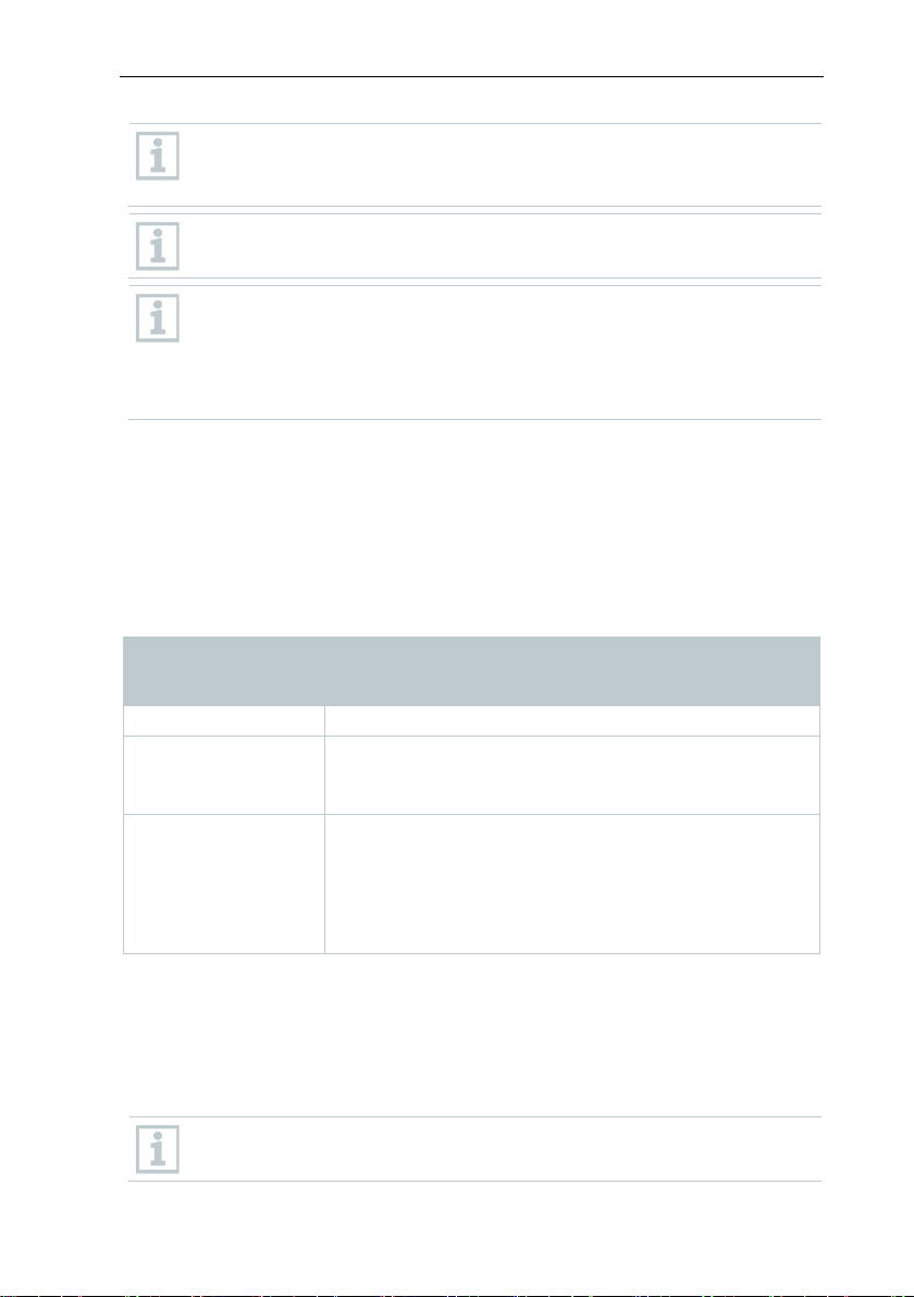
6 Commissioning
Start
No
Ye
Integrate router
Register probe on
Insert batteries into
Register probe on
Connect GSM
Insert batteries into
Connect USB
Connect USB cable and
Base with
Use router?
No
Yes
Insert SIM card
6.1 Flowchart: Configuration for
6 Commissioning
monitoring stationary zones
GSM module?
cable and power
supply to base
power supply to base
antenna
probe
probe
Saveris base
Saveris base
13
Page 14
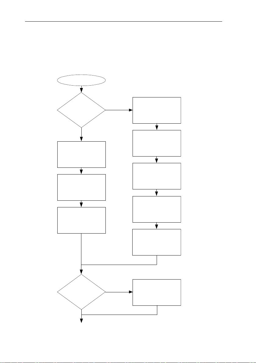
6 Commissioning
No
No
Mount hardware
Perform test run
Launch software
Create zones
Configure alarms
Start up hardware
Integrate converter
Use converter?
Use Ethernet probe?
Integrate Ethernet
Yes
Yes
End
Install software
using the startup
probe
wizard.
14
Page 15

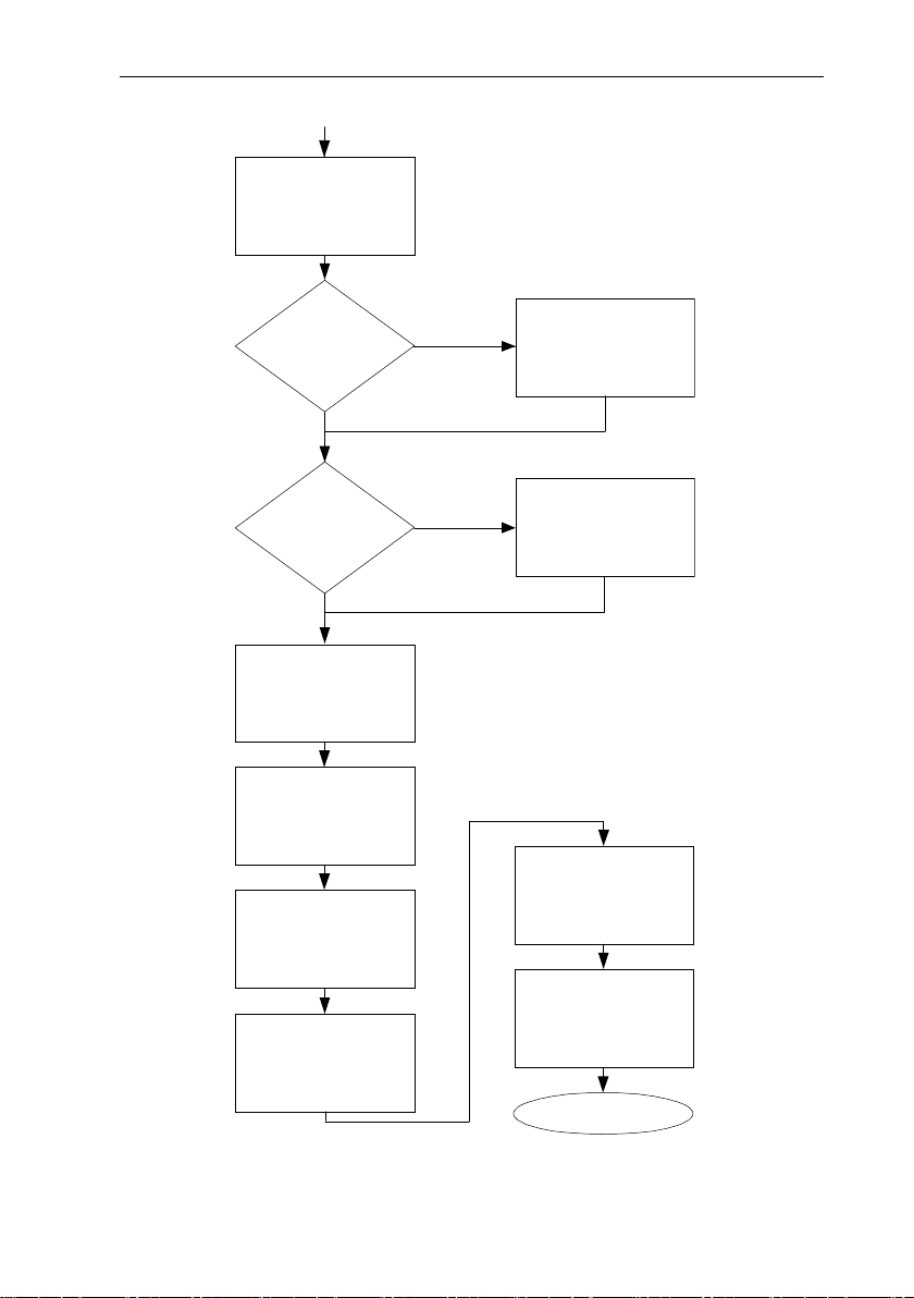
6 Commissioning
Connect USB
Register radio data
Use cockpit
Integrate cockpit unit
Base with GSM
Insert batteries into
Yes
No
Insert SIM card
Connect USB cable and
Register radio data
Insert batteries into
Connect GSM
Ye
No
Start
6.2 Flowchart (“Mobile monitoring”):
Configuration for transport monitoring
with Saveris radio data loggers
module?
power supply to base
cable and power
supply to base
antenna
probe
radio data logger
logger on Saveris
base
logger on Saveris
base
unit?
15
Page 16
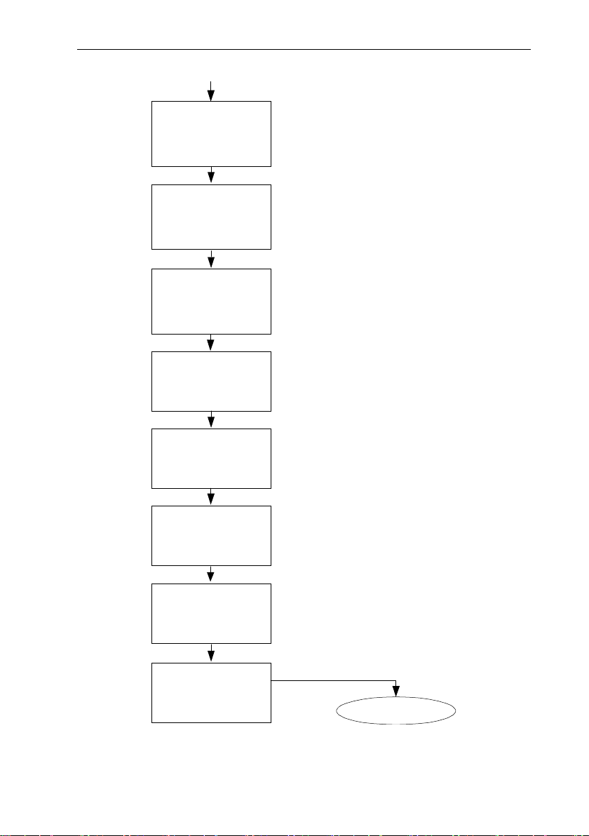
6 Commissioning
End
Install software
Connect Saveris
Integrate extender
Launch software
Perform test run
Mount hardware
Create zones
Configure alarms
base to PC and start
up hardware
16
Page 17
6 Commissioning
credit.
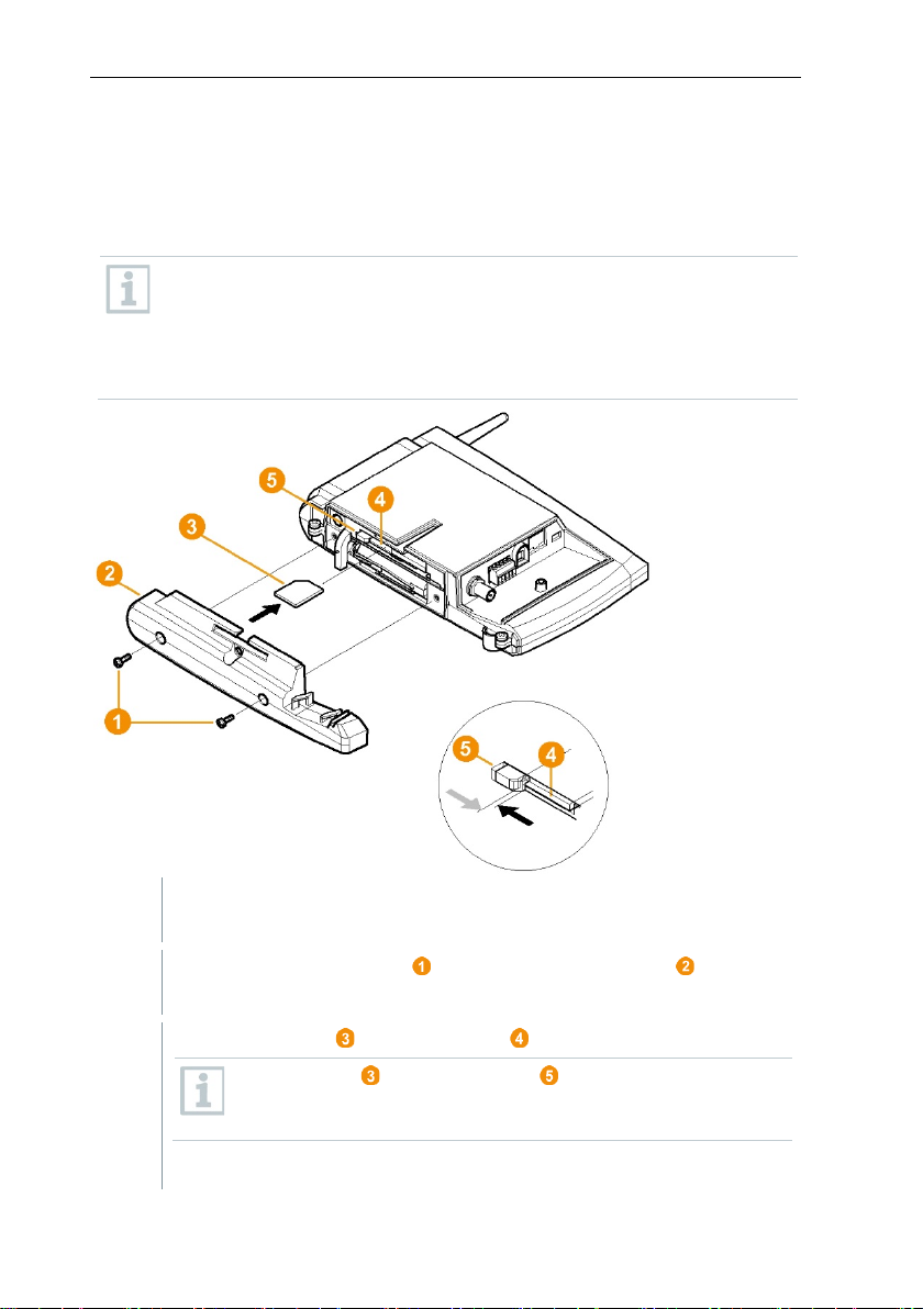
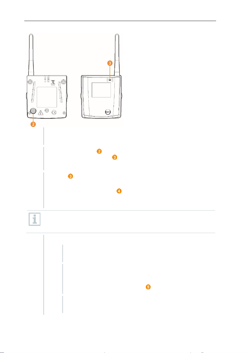
1
Switch off the Saveris base (with the Info Base view selected, press
2
Undo the screw connection and remove the base plate from the
3
Push the SIM card into the card slot as shown.
4
Place the base plate on the Saveris base and screw it down.
6.3 Commissioning the Saveris base
6.3.1 Inserting SIM card (optional)
For a Saveris base with integrated GSM module, you must insert the SIM card.
The SIM card for sending SMS messages is not included in the scope
of delivery and must be purchased separately from a mobile phone
provider.
It is recommended that you use a contract card instead of a so-called
prepaid card, as no alarm messages can be sent if you use up your
[ESC] briefly twice).
Saveris base.
The SIM card pushes the catch to the side as it is being
inserted. If the card is inserted, a spring pushes the catch back
and the SIM card is thus secured in the card slot.
17
Page 18
6 Commissioning
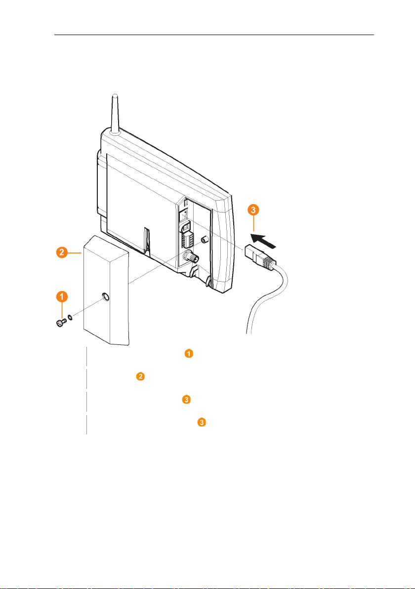
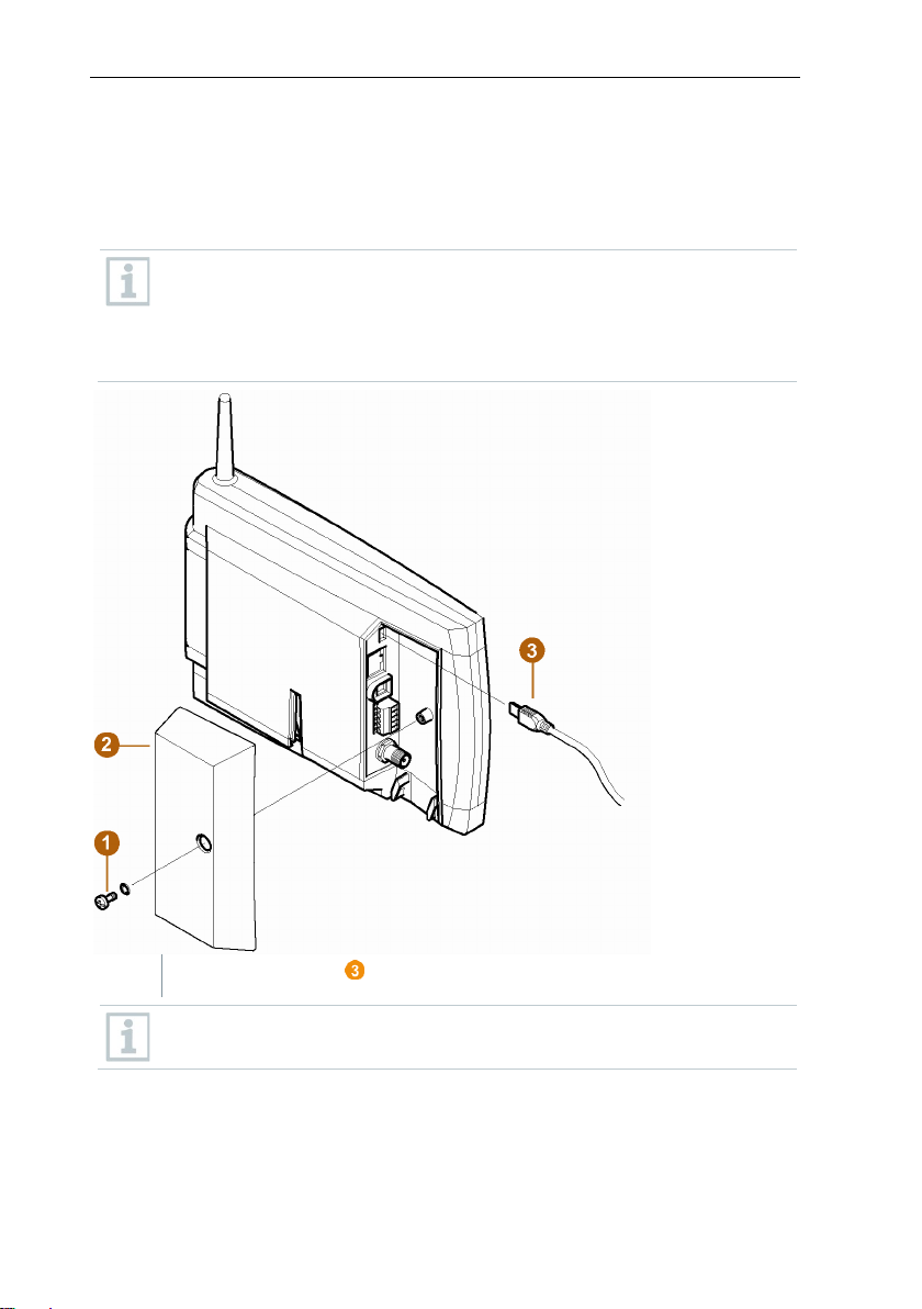
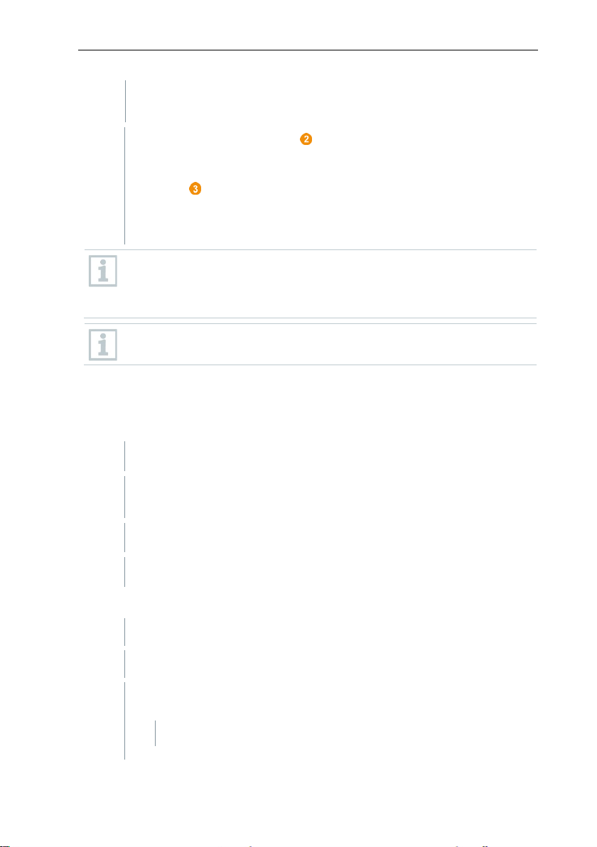
1
Undo screw connection and remove.
2
Take cover off Saveris base.
3
Plug the network cable into the Saveris base.
4
Connect the network cable to the Ethernet.
6.3.2 Connecting network cable to the Saveris
base
18
Page 19
6 Commissioning
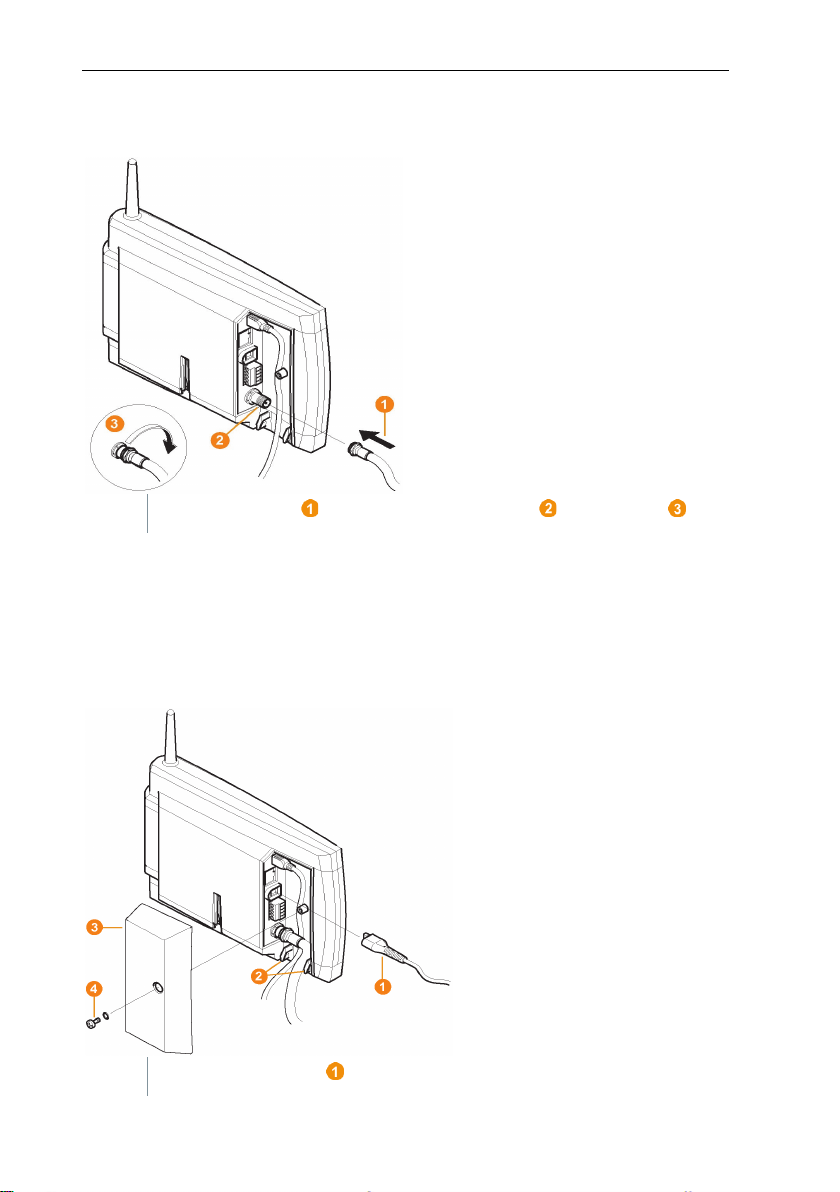
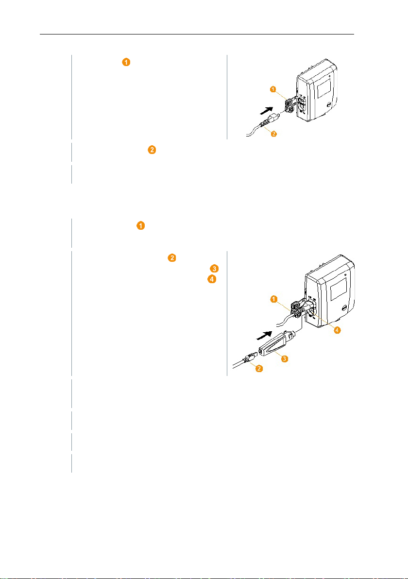
1
Fit antenna cable onto the coaxial connector and screw in .
1
Connect mains cable to the Saveris base.
6.3.3 Connecting GSM antenna (optional)
6.4 Connecting Saveris base to power
supply
You can connect the Saveris base to the power supply via the mains unit which
is included or via the 24 V AC/DC plug-in/screw terminal.
6.4.1 Power supply via mains unit
19
Page 20
6 Commissioning
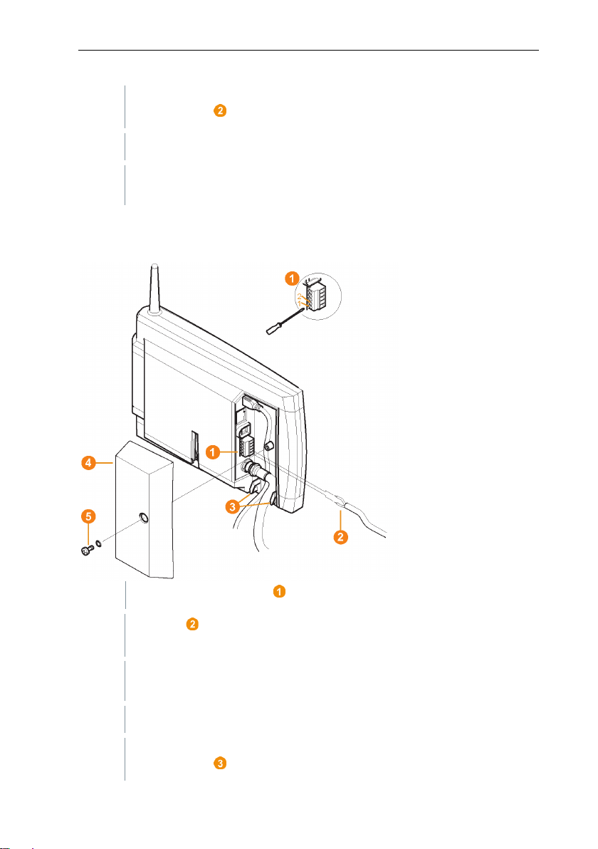
2
Ensure that cabling cannot be pulled out using a cable tie at the eyelets
3
Connect mains plug to the power supply.
1
Loosen clamping screws no. 1 and no. 2.
2
Put cable into the terminals as shown in the illustration. Observe
3
Tighten clamping screws.
4
Ensure that cabling cannot be pulled out using a cable tie at the eyelets
for strain relief .
The Saveris base automatically starts up and is ready for operation
once the language has been selected on the base.
6.4.2 Power supply via plug-in/screw connection
(optional)
permissible operating voltage!
The Saveris base automatically starts up and is ready for operation
once the language has been selected on the base.
for strain relief .
20
Page 21
6 Commissioning
1
Plug the USB cable into the Saveris base.
6.4.3 Connecting USB cable (optional)
For the commissioning, you can connect the Saveris base via a USB cable to
the computer on which the testo Saveris Client is installed. For this, first connect
the USB cable to the Saveris base.
During continuous operation, operate the Saveris base via the network
cable, not via the USB cable.
The USB connection works unreliably in combination with virtual
systems, which is why we recommend connecting the Saveris base via
Ethernet.
Do not screw on the cable cover of the Saveris base until after
commissioning and removal of the USB cable.
21
Page 22
6 Commissioning
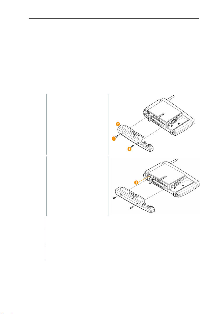
1
2
Plug the USB cable into
3
4
Via Start | All Programs | Testo | Testo Saveris Ethernet Wizard,
open the wizard for entering the connection settings.
5
Follow the wizard's instructions and assign the IP address for the
Saveris base.
6.4.4 Assigning an IP address to the Saveris
base (optional)
Generally, a static IP address should be assigned for the Saveris base, or an IP
reservation should be made on the DHCP server with the MAC address of the
Saveris base.
For assignment of the IP address, the software must be installed and the
programming adapter 0440 6723 must be present.
Undo screw connections
(1) and remove base plate
(2) from the Saveris base.
the testo programming
adapter (0440 6723) and
connect to the service
interface for the Saveris
base.
Connect the USB cable to the computer.
22
Page 23
6 Commissioning
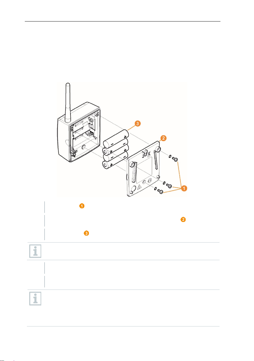
1
Undo screws on the rear of the Saveris radio data logger.
2
Remove housing cover of the Saveris radio data logger .
3
Insert batteries .
4
Place housing cover on the housing of the Saveris radio data logger.
5
Screw cover tightly onto the housing.
6.5 Commissioning of radio data loggers
in testo Saveris
6.5.1 Inserting batteries into Saveris radio data
logger
Ensure that you insert the batteries correctly.
The correct polarity is illustrated in the respective battery compartment.
A control switch is located in the housing which is actuated through the
cover. To this end, the cover must be screwed to the housing of the
Saveris radio data logger without any gap.
If the cover is not screwed on without any gap, the Saveris radio data
logger cannot be operated.
23
Page 24
6 Commissioning
Note that a maximum of 450 channels can be processed by the Saveris
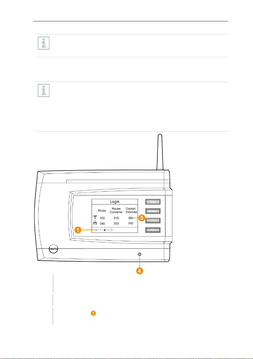
1
On the Saveris base, use the [▼] key to switch to the Info System
2
Press [Enter] to call up the Login function.
Transport tip: If the Saveris radio data loggers are to be sent via air
freight, the batteries must be removed beforehand to avoid inadvertent
radio communication.
6.5.2 Registering Saveris radio data loggers in
the system
You can register a maximum of 15 radio data loggers on the Saveris
base directly via radio.
In addition, you can operate 15 more radio data loggers per Saveris
converter and 5 more radio data loggers per Saveris router or router
cascade on the Saveris base.
menu.
software.
The status bar on the display indicates that the Saveris base is
ready for Saveris radio data logger detection.
24
Page 25
6 Commissioning
With the H2D/H4D Saveris radio data logger, the external humidity
3
Hold the connect key on the rear of the Saveris radio data logger
4
On the Saveris base,
4.1
Press the [Esc] key if there are no other components to be
Information about the necessary execution of the startup wizard
4.2
Press the [Enter] key if there is another component to be
probe must be plugged in.
pressed down until the LED on the Saveris radio data logger starts to
flash orange.
The LED on the Saveris radio data logger briefly turns green when
this has been detected by the Saveris base.
The LED on the Saveris base briefly flashes green and a prompt to
register more Saveris radio data loggers or Saveris routers appears in
the display of the base.
It is not possible to register multiple Saveris radio data loggers on the
Saveris base at the same time. Multiple Saveris radio data loggers can
only be registered one after the other.
registered.
is shown on the display for about ten seconds. The Saveris
base then switches to the Info System menu where the
number of registered components is now displayed.
registered; see previous step.
25
Page 26
6 Commissioning
5
Position Saveris radio data loggers precisely at their measuring points
6
Briefly press the connect key on the rear of the Saveris radio data
PC/laptop.
Common browser (e.g. Firefox as from version 50, Internet Explorer as
Power supply: via PoE (Power over Ethernet) or 5V DC micro USB.
Configuration: via A-A USB cable.
1
Insert the wireless stick into the USB 2 port.
2
Connect the gateway to the PC to USB 1 via the USB cable.
3
Connect the gateway and PC to the power supply (if the battery power is
After a start time of approx. 30 seconds, the gateway is ready to use.
to check the radio link.
logger.
If the LED on the Saveris radio data logger flashes
• green, there is a radio link.
• red, there is no radio link.
If there is no radio link to the Saveris base, even after a change of
location of the Saveris radio data logger, register a router on the
Saveris base; see section 6.9.5, testo Integrating a Saveris router
(optional).
In order to complete the commissioning of the Saveris radio data
logger, the latter still has to be configured using the startup wizard.
6.6 BT Gateway for testo 182
6.6.1 Equipment required
from version 8, Google Chrome)
6.6.2 Establishing connections to the gateway
too low).
26
Page 27
6 Commissioning
If the status LED flashes green, the gateway is in configuration mode.
4
Check the network settings of your PC. The gateway must be detected
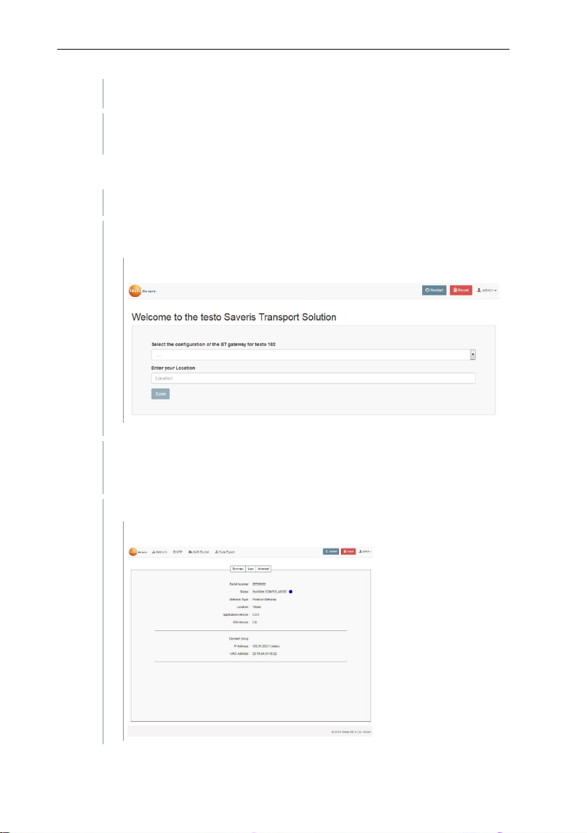
1
Open the configuration interface for the gateway via the browser.
2
Enter the default configuration IP address of the gateway
3
Select the Gateway type (registration or readout gateway) (Select
Location.
4
Save information: [Save]
as an RNDIS device (driver is loaded automatically).
6.6.3 Configuring the BT Gateway for testo 182
(172.31.250.1) in the address line.
The following window is displayed:
your testo Saveris Gateway BT configuration) and enter your
The following window is displayed:
27
Page 28

6 Commissioning
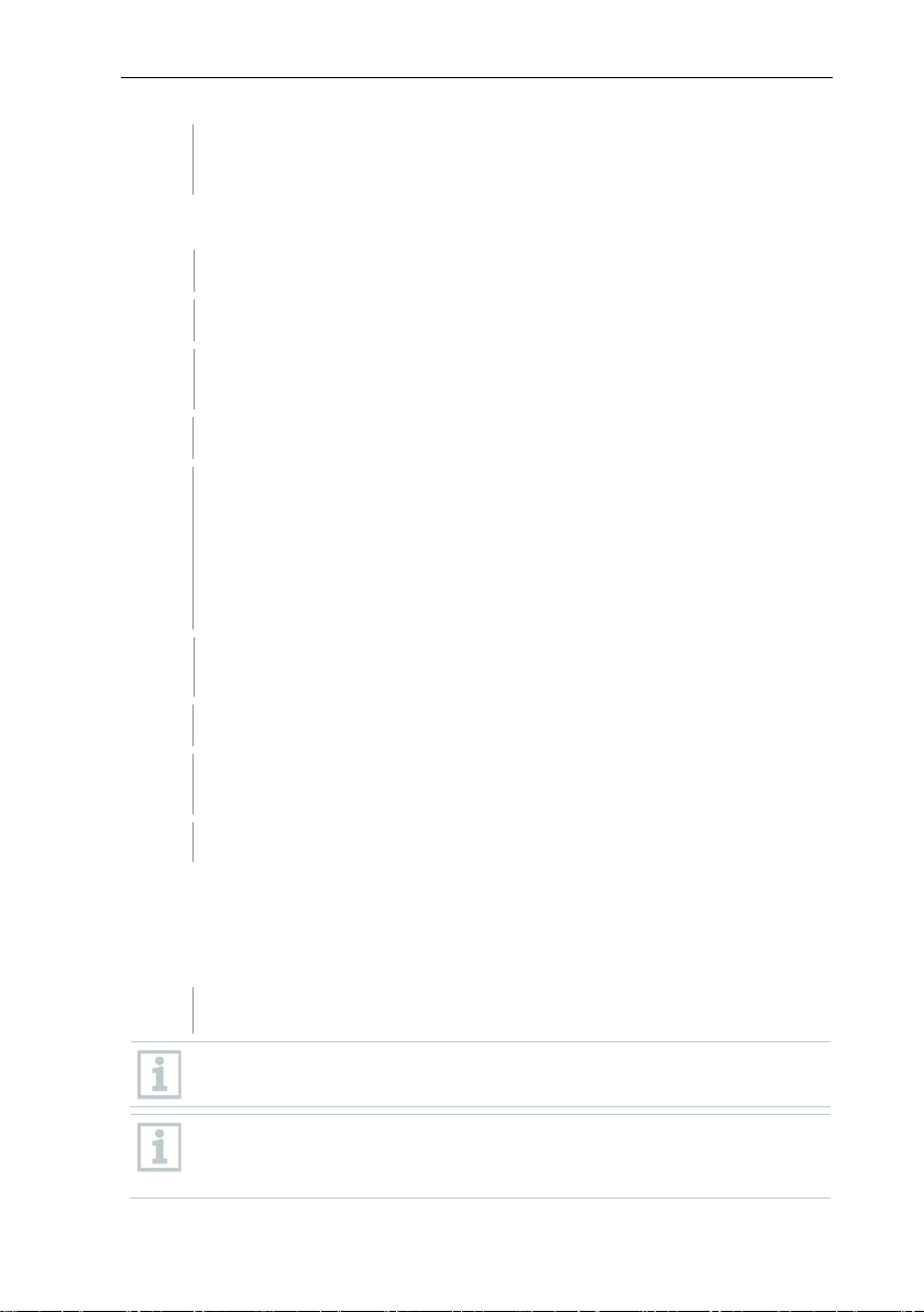
5
Click on the Network tab to configure the network.
1
Select whether the gateway is to be operated via DHCP or manual IP
2
Enter the network name.
3
Select the security.
4
Fill in the remaining fields (if security is not set to ‘None’).
5
Confirm your settings for the Network tab with [Save].
6
Confirm changes to the NTP configuration by clicking on [Save].
A connection can be established via Ethernet or WLAN.
Only one connection type (WLAN or Ethernet) is possible
at a time.
6.6.3.1 Configuring operation via WLAN
configuration.
Manual IP selection: Enter the following data for a static IP
configuration:
• the required IP address
• the subnet mask
• the default gateway
DHCP selection: no further settings necessary.
• DNS server (optional)
Optional: carry out NTP (time server) configuration.
The NTP servers transmit the date and time to the gateway. If
necessary, the NTP servers already entered by Testo can be
adjusted
Make a note of the gateway’s newly assigned IP address.
28
Page 29

6 Commissioning
1
Select whether the gateway is to be operated via DHCP or manual IP
2
Confirm your settings for the Network tab with [Save].
3
1
Click on the AWS Bucket tab at the top to configure your bucket.
2
Confirm your settings for the AWS Bucket by clicking on [Save]. The
3
Restart to confirm the settings
longer than 30 seconds.
6.6.3.2 Configuring operation via Ethernet / LAN
configuration.
Manual IP selection: Enter the following data for a static IP
configuration:
• the required IP address
• the subnet mask
• the default gateway
• DNS server (optional)
DHCP selection: no further settings necessary.
Optional: carry out NTP (time server) configuration.
The NTP servers transmit the date and time to the gateway. If
necessary, the NTP servers already entered by Testo can be
adjusted.
Make a note of the gateway’s newly assigned IP address.
Confirm changes to the NTP configuration by clicking on [Save].
6.6.3.3 Configuring the AWS Bucket
A gateway configured as a registration gateway can only be
assigned to one bucket. A gateway configured as a readout
gateway can be connected to multiple buckets.
access data are checked and if the connection was successful,
confirmation is displayed.
Network and AWS Bucket settings can later be changed at
any time. Changing the gateway type and the location is only
possible via a factory reset. To do this, press the Reset key for
29
Page 30
6 Commissioning
The gateway will now restart and the status LED will flash blue during
the status LED lights up solid green.
1
Disconnect the BT Gateway for testo 182 from the power supply.
2
Remove USB wireless stick.
3
Insert USB flash drive with the firmware update package (at highest
folder level) into USB 2.
4
Update is carried out automatically.
5
USB port.
5
Reinsert USB wireless stick into USB 2.
6
Restart BT Gateway for testo 182 with the new firmware: unplug and
plug in the power supply.
The Gateway is now ready for operation.
Before the installation: End all running programs.
the start-up process. As soon as the gateway is ready for operation,
6.6.4 Carrying out firmware updates
Connect BT Gateway for testo 182 to the power supply.
• Update successful: LED flashes green 10 times and gateway shuts
down
• Update failed: LED flashes red 5 times
• Error with update: repeat steps 1 to 4. Make sure that the firmware
update package was correctly saved on the USB flash drive.
Remove USB flash drive with the firmware update package from the
6.7 Commissioning testo Saveris software
6.7.1 Installing testo Saveris software
Administrator rights are required for installation.
30
Log in directly as the administrator, not via Execute as….
If you are installing multiple clients in a network, make sure that no
simultaneous changes are made to the system configuration by the
clients during simultaneous operation of them.
Page 31
6 Commissioning
1
Insert CD with the testo Saveris software into the CD-ROM drive. If the
2
Select the required installation options.
3
Follow the installation wizard’s instructions.
called SA password, the password
etected as new hardware when connected to
4
After completing the installation, restart the computer and log in with the
installation program does not start automatically, open Windows®
Explorer and start the file index.html on the CD.
Once you have for instance received the installation file via e-mail, use
the Setup.exe file at the highest level of the installation medium.
During installation, the version provided of the Microsoft® SQL Server
Express database environment is installed – if this is not already
present.
®
The database is protected by the sofor the database administrator, to prevent unintentional changes to the
database.
When installing testo Saveris Client and testo Saveris Viewer, note that:
the testo Saveris Professional Viewer has only limited functionality. This means
you can for example analyze and process data sequences, but cannot configure
alarms or carry out report settings.
During installation, you require the name or IP address of the computer
on which the Saveris Professional Server is installed.
With the testo Saveris Professional Client, the USB driver for the
connection of the base is installed for commissioning.
If the Saveris base is not d
the computer, the driver must be installed manually.
same user name as before.
6.7.2 Installing Saveris mail services
6.7.2.1 Installing MAPI mail
The installation of MAPI mail should only be carried out by a system
administrator.
The following requirements must be met for the installation of MAPI mail:
• MS Outlook must be available or installed on the PC for Saveris MAPI mail.
• A Microsoft Exchange server must be available or installed.
31
Page 32

6 Commissioning
1
Insert CD with Saveris software into the CD-ROM drive.
2
Select Installation of a connector for the Microsoft Exchange mail
3
Click on [Next].
4
Enter the Microsoft® Exchange
• An email account must be set up on the Microsoft Exchange server for the
user account used for MAPI mail.
• The name of the Microsoft Exchange server must be known for the
installation.
• MAPI mail must be installed on the Saveris server. The following applies to
this PC:
o A Microsoft Exchange server must be accessible.
o The Exchange server must be located in the same domain as the
Saveris server.
o The connection data for the Exchange account must be set up on the
PC. This is generally achieved by running MS Outlook once on this
computer.
Lotus Notes can be used with an adapter that is available for purchase.
Setup and configuration should be carried out by the respective IT
manager.
If the installation program does not start automatically, open Windows®
Explorer and start the index.html file on the CD.
server.
The installation wizard is started.
server name and the Exchange
server mailbox name on the
Microsoft
The name of the email mailbox is normally identical to the user name.
®
Exchange Server.
32
Page 33

6 Commissioning
5
Click on [Continue].
6
Enter the user name (Domain user)
7
Click on [Continue].
The name of the SMTP server must be known.
An email account with an Internet provider must be available or has to
The provider data (email address and mailbox) must be known.
1
Insert CD with Saveris software into the CD-ROM drive.
2
Select Installation of a connector for an SMTP mail server.
3
Click on [Next].
of the email mail box on the Microsoft
Exchange server.
Enter Password and Repeat
Password.
MAPI mail is installed.
6.7.2.2 Installing SMTP mail
The following requirements must be met for the installation of SMTP mail:
be set up.
If the installation program does not start automatically, open Windows®
Explorer and start the index.html file on the CD.
The installation wizard is started.
Only enter your address and password if authentication is required in
your application.
33
Page 34

6 Commissioning
4
Select the mail server or enter the mail
5
Click on [Continue].
You need to install the testo Saveris Client software, the SQL database
TestoSaverisViewer folder on the testo Saveris CFR CD.
1
Insert CD with the testo Saveris transport add-on into the CD-ROM
drive.
2
Install it in the transport add-on of the SQL database by executing the
Setup.exe file in the TestoSaverisTransportPrerequisites folder.
3
Activate the transport certificates by executing the
RegTestoDevCerts.exe application in the RegTestoDevCerts folder.
4
loggers.
server.
SMTP mail is installed.
6.7.2.3 Installing testo Saveris CFR transport add-on
Administrator rights are required for installation. Log in directly as the
administrator, not via Execute as…
and the testo Saveris Viewer software to display the transport data. To
do this, follow the installation instructions for the testo Saveris CFR
software and then execute the Setup.exe file in the
Optional: If you are using the testo 184 transport data logger, you can
install the 3 software versions which are needed for different
applications. To do this, run the relevant Windows installer in the subfolders:
1. t184cfgtmpl: Software for the creation of configuration
templates.
2. t184cfguser: Software for the configuration of testo 184 transport
data loggers when using previously created configuration
templates.
3. t184saveris: Software for the readout of testo 184 transport data
34
Page 35

6 Commissioning
5
the same user name as before.
1
Start the testo Saveris Client software.
In order to be able to connect an AWS bucket, the required permissions
Admins.
2
Select System Information -> AWS Settings.
3
Enter the AWS bucket information into the mask.
4
Save the entry.
The Saveris base is ready for operation.
the Saveris base.
The Saveris software is installed on the computer.
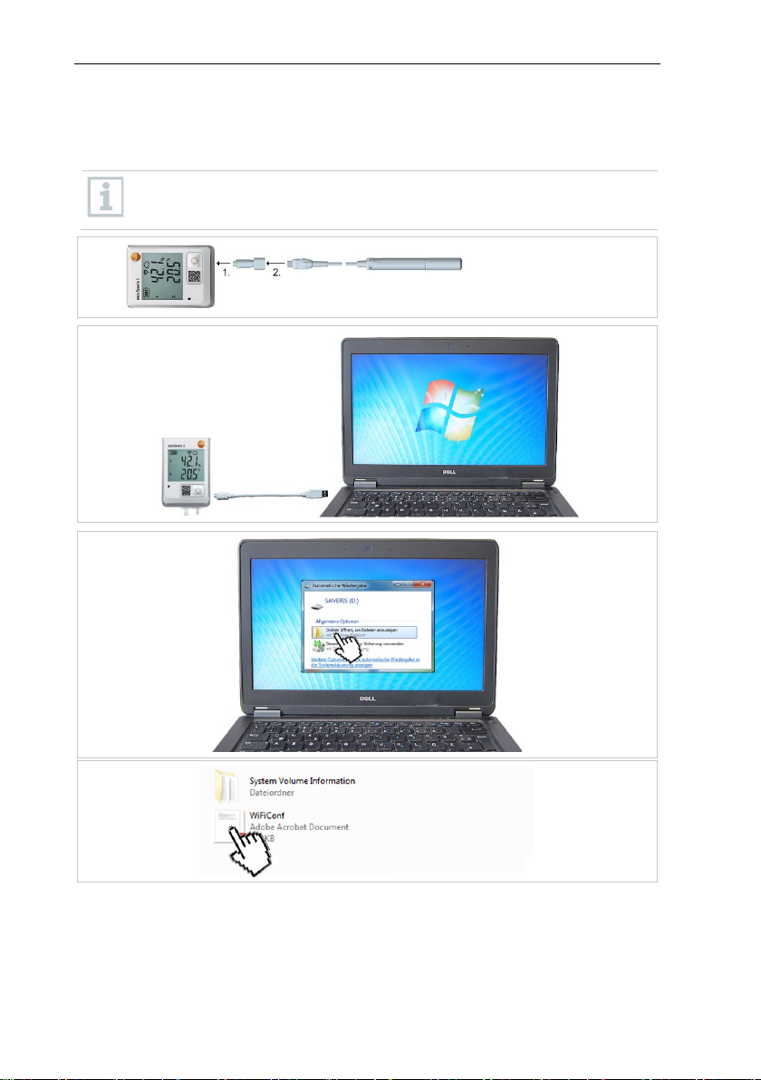
1
Ethernet.
Take into consideration that, if applicable, the testo 184 software
versions have to be installed on different computers, depending on the
application.
After completing the installation, restart the computer and log in with
Setting up a connection to the AWS bucket in the testo Saveris CFR
software
first have to be granted via 21 CFR 11 → Access Control →
6.8 Initial commissioning of the hardware
The following preconditions must be fulfilled for the commissioning of the
hardware:
All system components (data loggers, probes, etc.) are registered on
Connect the Saveris base to the computer via the USB cable or
35
Page 36

6 Commissioning
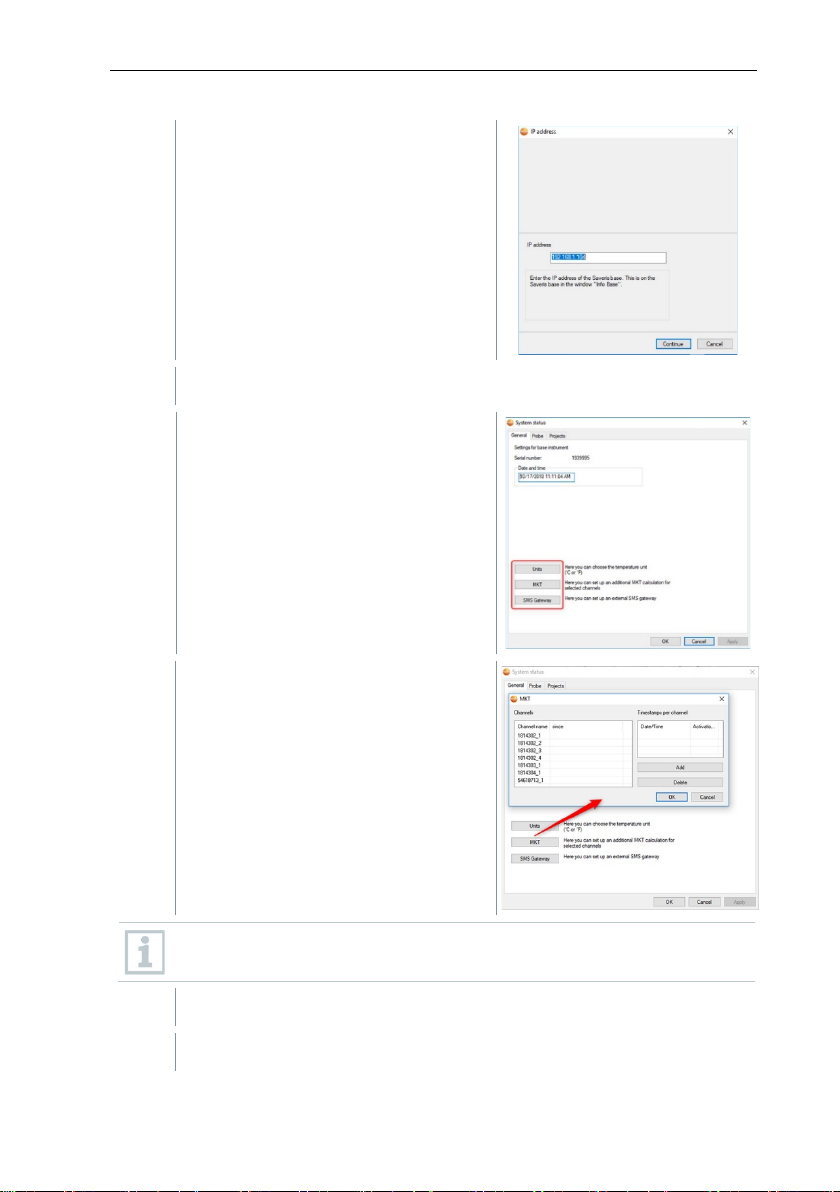
2
Click on [Next >].
3
Enter the IP address of the Saveris
4
Click on [Continue].
The Settings for base instrument
The startup wizard is launched.
base. This is located on the Saveris
base in the Info Base window.
of the Saveris base are displayed.
Date and time settings will be automatically adopted from the PC. The
administrator must make sure that the system time is regularly
compared with a reliable time source and adjusted if necessary, so as
to ensure the authenticity of the measurement data.
36
Page 37

6 Commissioning
5
Click on [Units] to select the
For using the external SMS gateway
1
Auf [SMS Gateway] klicken.
2
Option Use an external SMS
Empfänger Ports eingetragen.
3
Auswahl mit [OK] bestätigen.
4
Base neu starten.
6
Confirm selection with [OK].
7
Click on [Next >].
temperature unit for the system
(Celsius °C or Fahrenheit °F).
RV50, the option USE AN
EXTERNAL GATEWAY must be
checked. In addition, the IP address
and the ports (sending and receiving
ports) need to be
entered.
Gateway“ aktivieren, IP-
Adresse und die Sende- und
Bei Verwendung des internen GSM
Moduls muss die Option Use an
external SMS Gateway deaktiviert
werden.
The list of the data loggers registered
on the Saveris base is shown.
37
Page 38

6 Commissioning
8
To distribute the data loggers/probes already registered on the system
9
Open the selection list via the button and select the zone which the
10
Click on [Next >].
11
Click in the TC type field and enter the
12
If required, change the default values in the Probe name and Channel
13
If required, import adjustment data for the individual probes: Click on
14
Click on [Next >].
to stationary or mobile zones (for Saveris mobile), depending on the
purpose: Click on [Add stationary zone] or [Add mobile zone].
data logger should be assigned to.
thermocouple element type (K, J, T or
S), if this information is necessary for
the instrument.
name fields.
Assign channel names that are not longer than 20 characters.
[Import adjustment data].
If the Saveris base is equipped with a
GSM module, the dialogue for
entering the basic settings for the
SMS service (Settings for SMS
module) is shown.
If there is no GSM module, continue
as from step 13.
38
Page 39

6 Commissioning
15
Enter the PIN in the field of the same name.
If the PIN entered is incorrect, the Saveris base must be shut down and
card. Until this is done, the original
To unblock a SIM card: insert the card into a mobile phone and unblock
16
Click on [Next >].
17
Enter Measuring cycle and define the unit for it.
The measuring cycle determines the intervals at which a new reading is
18
Click on [Next >].
You can for example find the PIN in the documents for your SIM card.
The number of the SMS centre can be read out from the SIM card.
started up again with a different SIM
SIM card cannot be used and reconfigured.
The settings for the measuring cycle
are displayed
it by entering the PUK code.
saved in the Saveris base.
At a later stage, the settings can be changed for every data
logger/probe separately in the software.
If a router is registered on the Saveris
base, the configuration of the
connection type (Configure
connections) for the probes is shown.
If you have not registered a Saveris
router, continue as from step 24.
39
Page 40

6 Commissioning
19
Click in the Connection type cell of the data logger which needs to be
20
Use the button to open the selection list and select the Saveris router
21
Perform steps 16 and 17 for all other data loggers with measurement
22
Click on [Next >].
23
Postpone start of measurement if necessary.
24
Change the Project name in the project name field.
25
Click on [Finish] to end the commissioning of the hardware.
assigned to a Saveris router.
The cell is shown as a selection list.
which the data logger needs to be assigned to.
Data loggers which are in a mobile zone cannot be assigned to a
Saveris router.
data that need to be transmitted to the Saveris base via a router.
The information about the start of
measurement and the project name
are displayed.
Think of a unique name for the project that you will be able to easily
associate with the project later.
The project name cannot subsequently be changed.
The dialogue for the conclusion of the
commissioning is shown.
40
Page 41

6 Commissioning
26
Press the [Connect] key on all data loggers and Saveris routers one
27
Close the dialogue with [OK].
The Saveris base is ready for operation.
All data loggers are registered on the Saveris base.
The Saveris software is installed.
A project has already been created.
Measurement operation has been ended.
1
Connect the Saveris base via the USB or network cable to a computer
For continuous operation of the system, connection of the Saveris base
2
Click on [Next >].
after the other to synchronize the components.
The hardware is now ready for operation.
For how to mount the hardware on the wall for example, see section
6.10.3 Wall mounting of data loggers
.
6.9 Configuring hardware
Use the installation instructions for the initial commissioning of the system.
The following requirements must be fulfilled for the rest of the hardware
commissioning process:
on which the Saveris Client is installed.
to the computer via an Ethernet cable is recommended.
The startup wizard is launched.
41
Page 42
6 Commissioning
3
Enter the IP address of the Saveris
4
Click on [Continue].
5
Click on [Units] to change the
6
Click on [MKT] (Mean Kinetic
7
Click on [OK].
8
Make any further changes to the existing system settings as required.
base. This is located on the Saveris
base in the Info Base window.
temperature unit for the system.
Temperature) to simulate the effect of
temperature fluctuations over a
specific period of time.
1. Mark the channel.
2. Click [Add] to start the MKT
calculation for the selected
channel.
Several timestamps can be set for each channel.
42
Page 43
6 Commissioning
data loggers.
2
3
4
1
6.9.1 Integrating testo Saveris 2 H2 WLAN data logger
This section only describes the integration of the H2 WLAN data
logger into a measurement system, not the integration of other WLAN
43
Page 44

6 Commissioning
5
6
7
8
44
Page 45

6 Commissioning
period of time, the Saveris base should be assigned a fixed IP address.
1
Undo screws on the rear of the data
6.9.2 Integration of Ethernet data loggers into testo Saveris (optional)
In addition to the wireless Saveris data loggers, you can use data loggers that
are connected to the Ethernet interface of the Saveris base. This enables data
transfer from data loggers to the base even over long stretches if you do not
wish to use a Saveris router or Saveris converter.
All Ethernet components (Saveris Ethernet data logger, Saveris converter,
Saveris extender or base if applicable) must be assigned IP addresses by the
programming adapter (0440 6723) via the Ethernet wizard.
If your computer has the Dynamic Host Configuration Protocol (DHCP),
the Ethernet components automatically retrieve the IP address.
Because the DHCP address changes as standard following a certain
The IP address of the Saveris base must be manually assigned to the
data loggers, extenders and converters by the programming adapter.
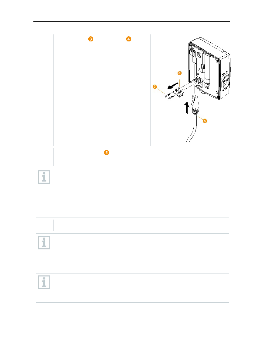
6.9.2.1 Connecting network cable
This section contains all the required information for this.
You can connect several Saveris Ethernet data loggers to the Saveris
base using a so-called switch. In this connection, note that a maximum
of 150 data loggers can be registered on the Saveris base or 450
measurement channels recorded there.
Only use high-quality network cables with a diameter between 5.8 mm
and 6.8 mm to ensure leaktightness of the data logger housing.
Only use cables with an intact snap clip.
logger and remove housing cover.
45
Page 46
6 Commissioning
2
Undo screws on the panel for the
3
Slide network cable with the tongue pointing up into the Ethernet port
in/screw terminal and not via the mains
4
Place the housing cover on the data logger and screw it down.
on
network cable and remove panel.
until it clicks into place.
If you wish to connect the Saveris Ethernet data logger to the power
supply via the 24 V AC/DC plugadapter, do not screw on the housing cover until after connecting the
power supply.
The procedure for connecting the power supply via the plug-in/screw
terminal is the same as for the Saveris router; see section 6.9.5.1
Connecting testo Saveris router to power supply (mains unit).
You can integrate the data logger into the network via a network switch.
6.9.2.2 Connecting testo Saveris Ethernet data logger to power supply (mains unit)
The procedure for connecting the power supply via the 24 V AC/DC
plug-in/screw terminal is the same as for the Saveris router; see secti
6.9.5.1 Connecting testo Saveris router to power supply (mains
46
unit).
Page 47
6 Commissioning
1
Open cover for power supply.
2
Insert mains cable .
3
Insert mains plug into a socket.
1
Open the cover of the service interface on the Saveris Ethernet data
2
Connect the USB cable to the testo
With the H4E Saveris Ethernet data logger, the external humidity probe
3
Connect the USB cable to the computer.
4
Follow the installation wizard’s instructions.
6.9.2.3 Connecting USB cable and installing driver (optional)
logger.
programming adapter (0440 6723)
and plug into the service interface .
must be plugged in.
The driver installation wizard is started.
47
Page 48

6 Commissioning
1
Under Start | All programs | Testo, click on Testo Saveris startup
6.9.3 Integrating testo Saveris analog coupler (optional)
Using a Saveris analog coupler, you can integrate a transmitter with
standardized current/voltage interfaces into the testo Saveris measurement data
monitoring system and monitor it. This means the Saveris analog coupler
thereby enables you to integrate additional measurement parameters other than
temperature and humidity into the testo Saveris measurement data monitoring
system.
Integration of a Saveris analog coupler involves three steps:
1. Connect transmitter to the Saveris analog coupler.
2. Register analog coupler on the Saveris base.
3. Parameterize analog coupler.
Connect transmitter to Saveris analog coupler
You can supply the transmitter with power via the Saveris analog coupler or
select a separate power supply.
The circuit diagrams can be found in the Saveris analog coupler commissioning
instructions which are supplied along with the Saveris analog coupler.
Register Saveris analog coupler on the Saveris base
The U1 Saveris analog coupler is registered on the Saveris base like a Saveris
radio data logger, see section 6.9.2 Integration of Ethernet data logger into
testo Saveris (optional)
The U1E Saveris analog coupler is commissioned and registered on the Saveris
base like a Saveris Ethernet data logger, see section 6.9.2 Integration of
Ethernet data logger into testo Saveris (optional).
Parameterizing Saveris analog coupler with startup wizard
wizard.
The welcome dialogue for the startup
wizard is displayed.
48
Page 49

6 Commissioning
2
Click on [Next >].
3
Leave default setting and click on [Next >].
4
Select Scale (see type plate / transmitter operating manual).
5
Enter Display from and to (see type plate / transmitter operating
6
Select Unit. If the required unit is not available in the selection list: Add
7
Select number of Decimal places.
8
Click on [Set up sum channel], if a specific unit needs to be totalized.
The Commission new data logger
dialogue is displayed.
Saveris analog couplers can always only be included in the
configuration as additional elements and cannot be used as
replacements for existing ones.
The Scale dialogue is displayed.
The fields of the Scale, Display from, to, Unit and Decimal places
columns are initialized. These fields can be amended individually.
manual).
via [User-defined unit].
49
Page 50

6 Commissioning
9
Click on [Next >].
10
Click on [New stationary zone].
11
Open the selection list via the button and select the zone which the
12
Click on [Next >].
13
Click in the TC type field and enter the thermocouple element type (K,
14
If required, change the preset values in the Data logger name and
15
Click on [Next >].
16
Enter Measuring cycle and define the unit for it.
The measuring cycle determines the intervals at which a new reading is
The list of the data loggers recently
registered on the Saveris base is
shown.
data logger should be assigned to.
J, T or S), if this information is necessary for the instrument.
Channel name fields.
Assign channel names that are not longer than 20 characters.
The settings for the measuring cycle
are displayed.
saved in the Saveris base.
Possible settings for the unit:
• sec (second)
• min (minute)
• h (hour).
50
Page 51

6 Commissioning
17
Click on [Next >].
18
Click in the Connection type cell of the data logger which needs to be
19
Use the button to open the selection list and select the Saveris router
20
Perform steps 18 and 19 for all other data loggers with measurement
21
Click on [Next >].
22
Postpone start of measurement if necessary.
If a Saveris router is registered on the
Saveris base, the configuration of the
connection type for the probes is
shown.
If you have not registered a router,
continue as from step 25.
assigned to a Saveris router.
The cell is shown as a selection list.
which the data logger needs to be assigned to.
Data loggers which are in a mobile zone cannot be assigned to a
Saveris router.
data that need to be transmitted to the Saveris base via a Saveris
router.
The wizard is displayed with the
setting for the start of measurement
and with the list of newly registered
data loggers.
51
Page 52

6 Commissioning
23
Click on [Finish] to end the commissioning of the hardware.
24
Confirm the message by clicking [OK].
1
Connect the router to the power supply.
2
Register the router on the Saveris base.
3
Assign the radio probe to the Saveris router.
Saveris router. Mount the Saveris router in such a way that this data
A message about the successful configuration of the hardware is
displayed.
The new hardware is now ready for operation.
6.9.4 Integrating testo Saveris transmitter
Transmitters record readings from data loggers and transmit these via an
optional additional component (Ethernet module) by Ethernet connection. You
will find information about transmitters and the Ethernet module in the relevant
instruction manuals for the transmitters. When using the Ethernet module,
transmitters are integrated into testo Saveris in the same way as Ethernet data
loggers, see section 6.9.2 Integration of Ethernet data loggers into testo
Saveris (optional).
6.9.5 Integrating testo Saveris router (optional)
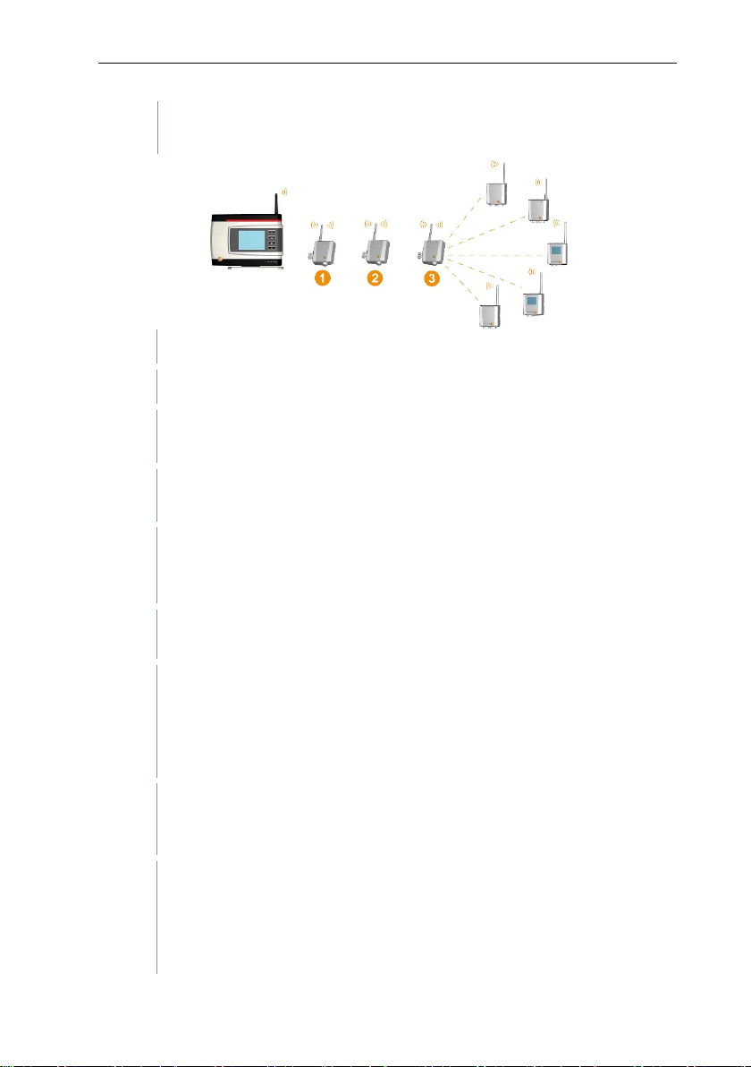
You can use a Saveris router to optimize radio communication under poor
structural conditions or to extend the radio path. The Saveris router receives the
signals from the data loggers and forwards them to the Saveris base. Maximum
extension of the radio path can be achieved by connecting three routers in
series.
The measurement data of up to five radio data loggers can be
transmitted to the Saveris base by each router or router cascade.
Up to 30 routers can be integrated into the measurement system. The
Integration of a Saveris router involves three steps:
Saveris base can communicate directly with a maximum of 15 routers.
When positioning a testo Saveris router, please note the following
points:
• When integrating several data loggers via a Saveris router, the data
logger with the weakest radio link determines the position of the
logger has an optimum radio link.
52
Page 53
6 Commissioning
• Data loggers and Saveris router should be mounted so that the
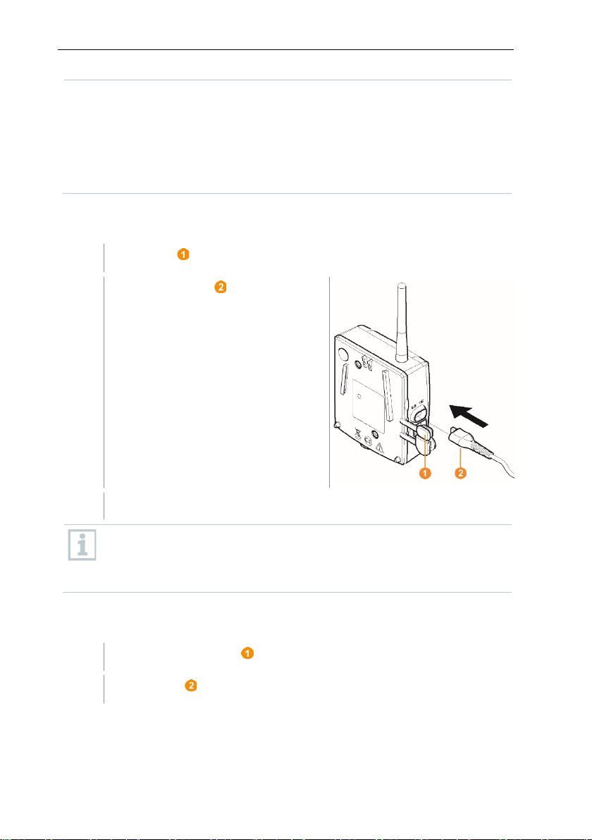
1
Open cover .
2
Insert mains cable .
3
Insert mains plug into a socket.
1
Remove protective cap .
2
Undo screws on the rear of the Saveris router.
antennas are pointing upwards.
• The radio link between the data loggers and the testo Saveris
router, as well as between the Saveris router and the Saveris base,
should as far as possible not be impaired by structural conditions
(walls, shelves, etc.). Mount the Saveris router and data loggers so
that a "visual contact" exists for as many radio links as possible.
6.9.5.1 Connecting testo Saveris router to power supply (mains unit)
The procedure for wall mounting a router is the same as for a probe;
see section 6.10. Installation of the components or section 6.10.4
Wall mounting of Saveris T1/T1D/T2/T2D/Pt/PtD/H4D radio data
loggers.
6.9.5.2 Connecting testo Saveris router to power supply (mains unit)
53
Page 54

6 Commissioning
3
Take housing cover off router.
4
Unscrew and remove cover cap of cable opening .
5
Loosen clamping screws .
6
Feed cabling through the cable opening and insert into the clamps
7
Tighten clamping screws.
.
It is not necessary to note the polarity.
Leaktightness and strain relief on the probe housing is only guaranteed
when using a PG screw connection.
54
Page 55

8
Place housing cover on the
9
Screw on housing cover .
10
Insert protective caps .
1
On the Saveris base, use the [▼] key to switch to the Info System
2
Press [Enter] to call up the Login function.
Saveris router.
The procedure for wall mounting a Saveris router is the same as for a
data logger, see section 6.10.4 Wall mounting of testo Saveris
T1/T1D/T2/T2D/Pt/PtD/H4D WiFi data loggers
6.9.5.3 Registering testo Saveris router
You can register a maximum of 30 Saveris routers to the Saveris base.
The Saveris base can communicate directly with a maximum of 15
Saveris routers.
6 Commissioning
menu.
The status bar on the display
indicates that the Saveris base is
ready for Saveris router detection.
55
Page 56

6 Commissioning
3
Hold the connect key on the rear of
same time. Multiple Saveris routers can only be registered one after the
4
Press the [Esc] key on the Saveris base if there are no other
5
Press the [Enter] key if there is another component to be registered;
1
Under Start | All programs | Testo, click on Testo Saveris startup
the Saveris router pressed down until
the LED on the Saveris router
starts to flash orange.
The LED on the Saveris router briefly turns green when this has
been detected by the Saveris base.
The LED on the Saveris base briefly flashes green and a prompt to
register more data loggers or Saveris routers appears in the display of
the base.
It is not possible to register multiple routers on the Saveris base at the
other.
components to be registered.
Information about the necessary execution of the startup wizard is
shown on the display for about ten seconds. The Saveris base then
switches to the Info System menu where the number of registered
components is now displayed.
see previous step.
6.9.5.4 Assigning data loggers
To assign a data logger to a Saveris router, both must be registered on
the Saveris base.
wizard.
56
Page 57

6 Commissioning
2
Click on [Next >].
3
4
Click in the Connection type cell of the data logger which needs to be
5
Use the button to open the selection list and select the Saveris router
5.1
Perform steps 4 to 5 for all other data loggers with measurement data
6
Position the data logger and Saveris router at their mounting locations
The welcome dialogue for the startup
wizard is displayed.
The System status dialogue is displayed with the General tab.
Switch to the Integrate router tab.
The direct connection type means that the data logger is directly
registered on the Saveris base or a Saveris converter.
assigned to a Saveris router.
The cell is shown as a selection list.
which the data logger needs to be assigned to.
that need to be transmitted to the Saveris base via a Saveris router.
to check the radio links.
57
Page 58
6 Commissioning
7
Briefly press the Connect key on the rear of the Saveris router.
8
Briefly press the Connect key on the rear of the data logger.
logger and/or Saveris router, use a Saveris converter; see section 6.9.6
All Saveris routers are connected to the power supply and registered on
1
Under Start | All programs | Testo, click on Testo Saveris startup
If the LED on the front of the router flashes
• green, there is a radio link to the Saveris base.
• red, there is no radio link to the Saveris base.
If the LED on the front of the data logger flashes
• green, there is a radio link to the Saveris router.
• red, there is no radio link to the Saveris router.
If there is no radio link even after changing the location of the data
Integrating Saveris converter (optional).
If you want to use data loggers within a router cascade, see section
6.9.5.5 Connecting Saveris routers in series.
6.9.5.5 Connecting Saveris routers in series
In each case, a maximum of three Saveris routers can be connected in
series, “cascaded”.
The measurement data of up to five Saveris radio data loggers can be
transmitted to the Saveris base per router cascade. The five Saveris
radio data loggers can be connected to any Saveris router in the
cascade.
A Saveris converter can be connected upstream of the router cascade.
the Saveris base.
wizard.
58
Page 59
6 Commissioning
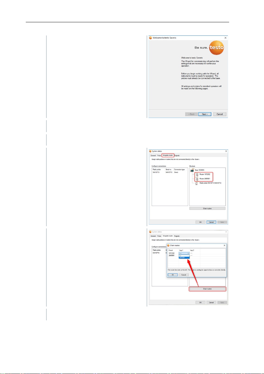
2
Click on [Next >].
3
4
Click on [Chain routers].
The welcome dialogue for the startup
wizard is displayed.
The System status dialogue is displayed with the General tab.
Switch to the Integrate router tab.
The Chain routers window is opened.
59
Page 60
6 Commissioning
5
Select Saveris routers in the order in which they should be connected in
6
Click on [OK].
7
Check assignment in the structure diagram and click on [OK].
8
Position the Saveris routers in their mounting locations to check the
9
Briefly press the Connect key on the rear of the router that is nearest to
10
downstream from the first router in the series (router 2 in the image).
11
Briefly press the Connect key on the rear of the Saveris router that is
series starting from the Saveris base (from left to right).
radio links.
the Saveris base in the series (router 1 in the image).
If the LED on the front of the router flashes
• green, there is a radio link to the Saveris base.
• red, there is no radio link to the Saveris base.
Briefly press the Connect key on the rear of the Saveris router that is
If the LED on the front of the Saveris router flashes
• green, there is a radio link to the Saveris router connected upstream
of it in the series.
• red, there is no radio link to the Saveris router connected upstream
of it in the series.
downstream from the second Saveris router in the series and is
therefore the furthest from the Saveris base (router 3 in the image).
If the LED on the front of the Saveris router flashes
• green, there is a radio link to the Saveris router connected upstream
of it in the series.
• red, there is no radio link to the Saveris router connected upstream
60
of it in the series.
Page 61
6 Commissioning
e to integrate data loggers into the
/Saveris routers
1
Briefly press the connect key on the rear of the Saveris converter.
converter is ready to detect the radio data logger.
2
flash orange.
The LED on the radio data logger/Saveris router briefly turns green
Saveris base.
If there is no radio link even after changing the location of the Saveris
router, use a Saveris converter; see section 6.9.6 Integrating Saveris
converter (optional). If you would lik
router cascade, see section 6.9.5.4 Assigning data loggers.
6.9.6 Integrating Saveris converter (optional)
If the distance between the Saveris radio data logger or Saveris router is too
large for a radio transmission, you can integrate a Saveris converter into the
measurement system. The Saveris converter is connected to the Saveris base
by means of an Ethernet cable and converts the radio signals to Ethernet
signals.
The measurement data from up to 15 radio data loggers
can be transmitted to the Saveris base with a Saveris converter.
You can connect several Saveris converters to the Saveris base using
a so-called switch. In this connection, note that a maximum of 150 data
loggers can be registered on the Saveris base or 450 measurement
Registering radio data logger or Saveris router on the Saveris converter
channels recorded there.
The procedure for preparing the commissioning of a converter is the
same as with a Saveris Ethernet data logger, see section 6.9.2
Integrating testo Saveris Ethernet data logger (optional).
The LED on the Saveris converter lights up green and the Saveris
Press the connect key on the rear of the radio data logger/Saveris
router until the LED on the radio data logger/Saveris router begins to
when this has been detected by the Saveris converter.
The radio data logger/Saveris router is registered on the Saveris
converter and the latter transmits the measurement data to the
6.9.7 Integrating Saveris extender1
The Saveris extender communicates automatically with all radio data loggers in
the system which are directly registered on the Saveris base or which have
been assigned to a mobile zone on the PC that are in its vicinity (e.g. when the
1
Component is only permitted for mobile monitoring in all countries with a radio
frequency of 868 MHz.
61
Page 62
6 Commissioning
then communicate via the appropriate Saveris extender. This is a major
reliable data transfer as a minimum retention time
The procedure for preparing the commissioning of a Saveris extender is
Integrating
truck is at the charging station). The mobile radio data logger must not be
registered on any Saveris router or Saveris converter.
The Saveris extender is used to pass on the collected logger data to the Saveris
base, along with data from the Saveris base to the Saveris cockpit unit.
The Saveris extender is designed for both mobile and stationary data
monitoring. In comparison to the Saveris converter, the main difference
is that the transmission paths of the components involved are not
strictly defined in the case of the Saveris extender. The radio data
loggers registered on the base each search for the best radio link and
advantage when the radio quality may change in terms of time or
spatial conditions, e.g. in a warehouse.
In principle it is preferable to use the Saveris extender rather than the
Saveris converter.
Please note that when using a stationary Saveris extender it is not
possible to trace the transmission/communication path of the
measurement data in the System software menu, because there is no
1 to 1 connection between the Saveris extender and the radio data
loggers or routers.
The measurement data of up to 100 radio probes can be transmitted to
the Saveris base using a Saveris extender. At least two cycles (30 min)
are recommended for
for the mobile unit on the ramp.
As the mobile radio data loggers only have a limited internal memory, it
is necessary to ensure that they come into radio contact with a Saveris
extender on a regular basis, depending on the measuring cycle, in
order to enable the measurement data to be transferred.
You can connect several Saveris extenders to the Saveris base via a
switch. In this connection, note that up to 20 Saveris extenders can be
registered on the Saveris base with a maximum number of 150 radio
data loggers or 450 measurement channels. If the connection is to be
made via VPN, please contact our support team.
the same as with an Ethernet data logger, see section 6.9.2
6.9.8 Integrating Saveris cockpit unit (optional)2
The Saveris cockpit unit is used to start and stop tours manually and to display
testo Saveris Ethernet data logger (optional).
the readings of the assigned Saveris radio data loggers during transport. The
driver is alerted about any violations of limit values by a red LED. In addition, the
2
Component is only permitted for mobile monitoring in all countries with a radio
frequency of 868 MHz.
62
Page 63
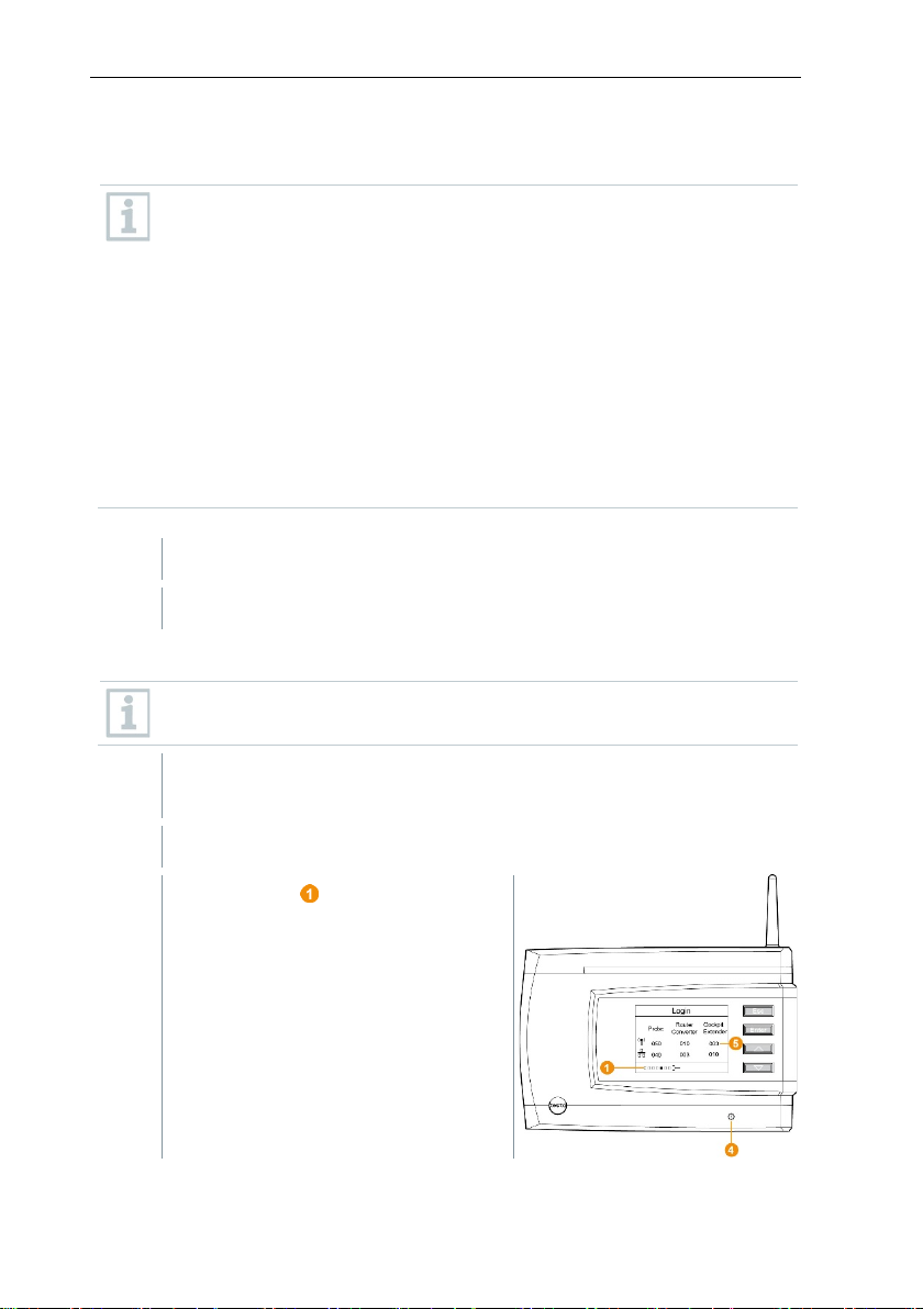
6 Commissioning
1
Register Saveris cockpit unit on the Saveris base.
2
Mount Saveris cockpit unit and supply with power.
1
On the Saveris base, use the [▼] key to switch to the Info System
2
Press [Enter] to call up the Login function.
tour data can be printed out by a Testo printer via infrared (0554 0549). A
cockpit unit can save several different tours with time marks.
A maximum of 50 Saveris cockpit units can be integrated into a testo
Saveris measurement data monitoring system.
The Saveris cockpit unit can display the measurement data of 2 groups
each comprising 4 radio data loggers (max. 32 channels). The data are
transferred every 15 minutes. Alarm events are forwarded immediately
to the Saveris cockpit unit.
The Saveris cockpit unit is only used to display the measurement data,
not for permanent storage. It is therefore important to ensure that the
mobile radio data loggers come into radio contact with a Saveris
extender or the Saveris base on a regular basis, depending on the
measuring cycle, in order to enable the measurement data to be
transferred.
The reading output can be configured via the testo Saveris software.
The integration of a Saveris cockpit unit involves two steps:
6.9.8.1 Registering Saveris cockpit unit
You can register a maximum of 50 Saveris cockpit units on the Saveris
base.
menu.
The status bar on the display
indicates that the Saveris base is
ready to detect the Saveris cockpit
unit.
63
Page 64

6 Commissioning
efly to the PC via the USB
3
Use [ ▲ ] and [ ▼ ] to select the required language on the Saveris
4
Press [Enter] to call up the Login function.
It is not possible to register multiple Saveris cockpit units on the Saveris
5
Press any key to confirm the information.
6
On the Saveris base,
Information about the necessary execution of the startup wizard
the display for about ten seconds. The Saveris base th
menu where the number of register
The Saveris cockpit unit can be connected bri
port for power supply while registering on the Saveris base. The driver
search, which opens automatically on the PC, can be closed.
cockpit unit.
The status bar on the display
indicates that the Saveris cockpit unit
is attempting to register on the
Saveris base.
base at the same time. Multiple Saveris cockpit units can only be
registered one after the other.
Once successfully registered, the Saveris cockpit unit displays a
warning about use in traffic.
Saveris cockpit unit menu is opened.
The Saveris base transfers the tour descriptions and mobile zones
created in the Saveris software to the Saveris cockpit unit.
Each time the mobile zones or tour descriptions are changed, the
Saveris cockpit unit must have a radio link to the Saveris base or a
Saveris extender to enable current data to be received.
• Press the [Esc] key if there are no other components to be
registered.
shown on
switches to the Info System
components is now displayed.
• Press the [Enter] key if there is another component to be
64
registered; see previous step.
Page 65

6 Commissioning
Ensure that the Saveris cockpit unit does not obstruct your line of vision
1
Push the mini USB cable into the
At below 15°C: warm the windscreen and sucker.
If the windscreen is dirty: clean the windscreen with a suitable cleaning
2
Secure the mount on the windscreen using the sucker.
3
Insert the mount into the guide until
4
Connect adapter (order no. 0554 1038) to the USB cable and plug into
6.9.8.2 Fitting Saveris cockpit unit in the driver's cab and connecting it to a power supply
Do not fit the Saveris cockpit unit while driving.
while driving.
Comply with road traffic regulations.
Always use the adapter supplied (order no. 0554 1038) for connection
to the vehicle electrical system. We recommend connecting to a
permanently supplied socket.
connection port .
agent.
you hear it click into place.
the socket of the vehicle electrical system.
Green LED lights up when the Saveris cockpit unit is supplied with
power.
Saveris cockpit unit is ready for use.
Before each trip, particularly when temperatures fluctuate, check that
the mount is secure.
65
Page 66

6 Commissioning
ion rechargeable batteries in the Saveris base and in the Saveris
1
Position wall bracket at the required
2
Using a pen, mark the locations for the fastening screws.
3
Prepare the fastening location for the attachment in accordance with
4
Fasten wall bracket using appropriate screws.
6.10 Installation of the components
It is absolutely essential to follow the notes in section 2 Safety and
disposal when installing the Saveris components.
Do not install the Saveris base and the data loggers at their locations
until the measurement system is functioning as expected.
The LiEthernet data loggers cannot be charged at sub-zero temperatures.
Avoid installation sites for these components with sub-zero
temperatures prevailing for extended periods of time.
After installation, perform another test run of the system; see section
6.10.1 Mounting the Saveris base on the wall
6.11 Performing test run.
When selecting the location for the Saveris base, please take into
account that this must be positioned close enough to the computer
used and a possible power supply in accordance with the cabling
provided.
The mounting materials (screws, dowels, etc.) are not included in the
scope of delivery.
location.
The distance between the fastening screws is 25 mm.
the material (e.g. drill hole, insert dowel).
66
Page 67

6 Commissioning
5
Place Saveris base on the wall
1
Place the Saveris base on the
2
Set up the Saveris base at the required location.
bracket and secure with screw .
6.10.2 Setting up Saveris base with the stand
When selecting the location for the Saveris base, take into account the
following points:
• The Saveris base must be on a level, non-slip surface.
• The Saveris base must be positioned close enough to the computer
used and a possible power supply in accordance with the cabling
provided.
stand .
67
Page 68

6 Commissioning
1
Position wall bracket at
2
Using a pen, mark the locations for the fastening screws.
3
Prepare the fastening location for the attachment in accordance with
the material (e.g. drill hole, insert dowel).
4
Fasten wall bracket using appropriate screws.
6.10.3 Wall mounting of data loggers
6.10.3.1 Wall mounting of T1/T1D/T2/T2D/Pt/PtD/H4D radio
data loggers
When selecting the location, take into account the following points:
• The range of the radio data logger must not be exceeded.
• Attach the radio data logger in such a way that the readings cannot
be falsified, e.g. by exposure to direct solar radiation.
The mounting materials (screws, dowels, etc.) are not included in the
scope of delivery.
the required location.
The distance between the fastening screws is 30 mm.
The wall bracket must be screwed on with the smooth surface facing
the wall.
68
Page 69

5
Push the radio data logger
onto the wall bracket
until it clicks into place.
6 Commissioning
The Saveris T1/T1D/T2/T2D/Pt/PtD/H4D radioi data loggers can be
protected against impact or high-pressure cleaning with the Saveris
protective housing (order no. 0572 0200).
The two halves of the protective housing are force fitted together, even
if the screw connection has already been loosened. To loosen them,
carefully use a screwdriver on the external screws. Do not damage the
surrounding seal in the process.
When assembling the Saveris protective housing, the screws must be
tightened and the unassigned connections must be sealed with the
supplied plugs to ensure IP protection to IP 69 K.
69
Page 70

6 Commissioning
(Suitable for: 0572 2035 01)
cable ties)
3
Padlock
4
Storage compartment for USB
port sealing plug
slide cable holder downwards.
6.10.3.2 Wall mounting of testo Saveris 2 H2 WLAN data loggers
The wall bracket ensures that the WLAN data logger is kept securely in place.
Mounting materials are not included in the scope of delivery. Select appropriate
mounting materials according to the required mounting location.
1 Wall bracket with slots for
mounting materials (screws or
5 Storage compartment for probe
socket sealing plug (left/right)
6.10.3.3 BT Gateway for testo 182 wall mounting
Mounting instructions
• The gateway must be positioned in such a way that the ambient conditions
do not interfere with the radio signal (WLAN and Bluetooth®). Example:
mounting in a highly metallic environment.
• For integration into a local WLAN, a minimum connection strength of 75 db is
recommended.
• Live cables can lead to an impairment of the radio signal. The network
infrastructure must ensure sufficient compliance with the required wireless
standards.
70
2
Securing pin
6 USB cable holder, folding: push
down on the spot marked with a
circle using a screwdriver and
Page 71

6 Commissioning
2
Mount BT Gateway for testo 182
3
• The maximum range of the reader in free field is at most 30 metres
(Bluetooth
®
).
• The BT Gateway for testo 182 may only be operated inside buildings
(protection class IP20).
Wall mounting
Make sure that the USB wireless
stick is inserted into USB port 2.
Option 1:
• Hang on the wall via the hook
eyelet on the bottom of the
gateway housing.
Option 2:
• Mount the top-hat rail (not included
in the scope of delivery) and click
the Gateway into place on the tophat rail.
Option 3:
• Use double-sided adhesive tape to
attach the Gateway to a clean
.
surface
Carry out the necessary wiring.
71
Page 72

6 Commissioning
1
2
Remove data logger from the wall bracket by moving upwards as
shown.
1
Perform another test run on the measurement system; see section 6.11
After mounting the hardware, check the system again to test the
6.10.3.4 Removing components from the wall bracket
Using a narrow slotted screwdriver,
unlock the data logger on the
wall bracket .
6.10.4 Checking the measurement system again
Performing test run.
measurement system is working perfectly.
This enables you to detect whether Saveris radioi data loggers are
located outside of the range of the Saveris base, if applicable, or if
there is interference to the radio link due to structural conditions.
72
Page 73

1
In the navigation area click on System.
2
Open the radio data logger input.
3
Click on a channel to open the settings and check the Radio quality.
4
Repeat step 3 for all other radio data loggers.
data logger for a considerable
data logger and the Saveris base by briefly pressing the connect key on
6.11 Performing test run
The test run must be performed to ensure flawless operation of the
measurement system.
6.11.1 Checking system availability
Wait for the first connection between the Saveris base and the data
loggers to check the system availability.
In the data window, the following inputs are displayed in the tree
structure:
• Base
• radio data logger
o radio data logger assigned to a stationary zone.
o radio data logger assigned to a mobile zone.
• Ethernet data logger
• Router
• Cockpit unit
• Extender
• Converter
An asterisk (*) after a component indicates that the synchronization of
this component with the system is not yet complete (e.g. in the case of
configuration changes).
6 Commissioning
The active channels of the radio data loggers registered on the system
are displayed.
If no values have accumulated for a radio
period of time, check whether a connection exists between the radio
73
Page 74

6 Commissioning
the Saveris radio data logger. The LED on the radio data logger
A Saveris base backup is recommended after a successful system test,
6.11.2 Performing system test
A simple system test includes the following:
• In the System main menu:
o All data loggers are visible, synchronization of the radio data loggers is
complete (none have an asterisk * after the name)
o All components have the current firmware version
o Under operating data: the data logger’s last data transfer was punctual
o The communication statistics of the individual data loggers are good
• In the data view of the zones:
o No noticeable alarms occurred during the maintenance period
o In the graphic (selecting individual measuring points), the measuring
point selections are regularly incorporated in the measuring cycle without gaps
• Generate and acknowledge at least one SMS or email alarm
• Wait for an automatic report or create it for test purposes under Options |
System test
• No open alarms in the overview window
• Where there is regulated user access: authorized employees have access to
the system in accordance with their rights
• In the Tours3 main menu:
o Readings and duration of tours carried out are correctly displayed.
o A tour blank can be generated from the data of the mobile zones via
[Define tour] which is displayed under Tours.
• On the Saveris cockpit unit:
o All mobile zones and tour descriptions configured in the software can
be selected in the Saveris cockpit unit under Tour settings.
o When the tour is active, limit value violations are shown on the display
and indicated via the red LED. They can be acknowledged on the
Saveris cockpit unit.
o Create test printout: All readings are printed out in a 15-minute cycle.
Additional lines and signature line appear on the printout as defined in
the software in the System main menu.
displays the connection status.
see section 7.1.2 testo Saveris base backup.
3
Only for mobile monitoring
74
Page 75
7 Maintenance
1
On the System tab in the System main menu, click the Backup
2
Activate Create a daily backup checkbox.
3
Select destination directory via Determine folder.
4
Click on OK.
1
On the System tab in the System main menu, click the Database
7 Maintenance
7.1 Data backup
7.1.1 Creating backup
7.1.1.1 Automatic backup of the Saveris data
The Backup settings function enables automatic cross-project backup of the
readings which are in the database on a daily basis. The backup files can be
imported into a new project using the Restore database function.
The destination directory for storage of the backup files must be
enabled for network services. Otherwise data backup is not possible!
For security reasons, backup files should be saved/archived on a
different PC to the Saveris database.
settings button.
The Backup settings window opens.
7.1.1.2 Manual backup of the Saveris data
The Backup database function enables cross-project backup of the readings
which are in the database at any time. The backup files can be imported into a
new project using the Restore database function.
The destination directory for storage of the backup files must be
enabled for network services. Otherwise data backup is not possible!
For security reasons, backup files should be saved/archived on a
different PC to the Saveris database.
backup button.
The Save as window opens.
75
Page 76

7 Maintenance
2
Select destination directory.
3
Name file.
4
Click on Save.
Saveris base is started up and connected to the PC.
1
Launch testo startup wizard.
2
Enter IP address of the Saveris base.
3
Click on the Projects [Base backup] tab.
4
Shut down the Saveris base: In the Info Base menu, briefly press [Esc]
5
Start up the Saveris base: press and hold down [Esc].
6
Confirm For backup, the base must be restarted software message
7
Select directory in which the backup file should be saved.
8
Click on [Save].
7.1.2 testo Saveris base backup
For backup, the base must be restarted message appears. Do not
confirm message.
twice.
Select language menu appears.
Do not press any other keys on the Saveris base.
with [OK].
*bi2 file with backup data is saved.
The stored data can only be imported to a Saveris base with the same
firmware version. The memory capacity of the target base must be
larger than or equal to that of the source base. For memory size, see
Select language window.
76
Page 77
7 Maintenance
• The free Microsoft® SQL Server® 2017 R2 Express database
• The possible duration of the recording is primarily determined by the
the database is full, the capacity of the database should be checked
up measures in good
1
Projects
Opens the dialogue for selecting a project
support team in the event of a problem.
System test
Use this function to test individual functions
support team.
To transfer the saved data to a Saveris base, please contact Customer
Service.
7.1.3 Checking the database capacity
environment is installed as standard with the testo Saveris software.
• The Microsoft® SQL Server® 2017 Express can manage databases
up to a size of 10 GB.
measuring rate with a constant number of channels.
If the Saveris base, for example, records the data from 20 channels
with a measuring cycle of 2 minutes, then the database can save
data for much longer than ten years in this configuration.
• Since the testo Saveris software does not generate an alarm when
at regular intervals in the Saveris startup wizard under the Projects
tab in order to enable the introduction of followtime.
You can get help with this procedure from our support team.
7.2 System settings
In this menu, determine the settings for the Saveris base, the radio data loggers
and – if installed in the measurement system – the Ethernet data loggers,
Saveris routers, Saveris converters, Saveris analog couplers, Saveris extenders
and Saveris cockpit units.
The following menus are displayed:
System | Management menu
Menu function Description
Logs Opens a log file that you can send to our
In the navigation area click on System.
of the Saveris system. Please contact our
77
Page 78
7 Maintenance
Creates a backup f
the directory where the backup file is to
Loads the previously saved backup file and
thus enables access to the saved proje
data.
1
Saveris Client
2
Select Project in the dialogue and
click on [Cancel].
3
Click on Options | Management |
Restore database.
4
database backup.
5
Server\MSSQL.1\MSSQL\Data\).
6
Confirm the following messages with
- Database is being recovered.
7
Close Saveris Client.
Opens the dialogue for configuring the
automatic backup.
Database backup
Restore database
ile for all projects.
Administrator rights are required and
be saved must be enabled for the
network service.
ct
Administrator rights and re-installation
of the system are required. The startup
wizard must not be launched before
restoring the database.
Open
.
Select the *bak file containing the
In the Find folder dialogue, select
the directory for the backup (e.g.
c:\Programs\Microsoft SQL
Backup settings
78
[OK]. The overview window of the
projects is only for information
purposes.
For security reasons, backup files
should be saved on a different PC to
the Saveris database.
Page 79

System | Security menu
Permissions
Limits zone access to certain user
accounts.
Audit trail
Display, save or export audit trail file.
Hash code
Generates a hash code
of data integrity.
Menu function
Description
Search
Opens a search window where you can searc
through zones and channels using a text word
search.
data loggers or
Menu function Description
7 Maintenance
Raw data export
Creates a vi2 file for each data logger with
all measurement data from the Saveris
base (not from the database) for verification
System | Search menu
In the data area, the following entries are displayed in the tree
structure:
• Base with the general settings of the Saveris base and of the
SMS module (if present), along with the operating data of the
radio data loggers
• Radio data loggers with the settings for the radio
wireless analog couplers which are registered on the Saveris
base. Radio data loggers which are assigned to a mobile zone
are marked with a tyre symbol.
• Ethernet data loggers with the settings for the Ethernet data
loggers or Ethernet analog couplers which are registered on
the Saveris base.
• Routers with the settings for the routers which are registered
on the Saveris base.
• Converters with the settings for the converters which are
registered on the Saveris base.
• Extenders with the settings for the extenders which are
registered on the Saveris base.
• Cockpit units with the settings for the cockpit units which are
registered on the Saveris base.
79
Page 80

7 Maintenance
1
Under Start | All programs | Testo, click on Testo Saveris startup
2
Click on [Next >].
3
Switch to the Projects tab.
7.3 Replacing components
You can shut down a component – Saveris radio data logger, Saveris converter
or Saveris router – at any time, because it is temporarily not being used or, for
example, in order to replace it with a new component in the event of a defect.
If the Saveris base is replaced, a new project must be created. If
necessary, contact our support team.
7.3.1 Deleting components
wizard.
The welcome dialogue for the startup
wizard is displayed.
The System status dialogue is
displayed with the General tab.
80
Page 81

7 Maintenance
4
Click on [De-register component].
5
Activate the checkbox in front of the component that needs to be de-
6
Click on [OK].
7
Confirm the prompt with [Yes].
8
After deleting a probe, briefly press the Connect key on the rear of the
The De-register component
dialogue is displayed.
registered from the system.
Before deleting a Saveris router, you should assign the assigned
Saveris radio data loggers directly to the Saveris base to ensure data
availability.
A prompt to remove the component from the configuration is displayed.
The component is deleted from the configuration.
Saveris radio data logger, so that the Saveris radio data logger no
longer attempts to transmit measurement data.
7.3.2 Adding new components
With the subsequent addition of a component, it may be the case that
the measuring cycle is not synchronous with that of the components
already present.
This results in readings seeming to be missing in the table view if
readings are not input from all Saveris data loggers at a point in time.
81
Page 82

7 Maintenance
1
Register new Saveris radio data logger on the Saveris base.
2
Launch testo Saveris startup wizard.
3
Click on [Next >].
4
Leave default setting and click on [Next >].
The startup wizard launches.
The Commission new
probedialogue is displayed.
The list of the Saveris radio data
loggers recently registered on the
Saveris base is shown.
82
Page 83

7 Maintenance
5
To distribute the Saveris radio data loggers already registered on the
6
Open the selection list via the button and select the zone which the
7
Click on [Next >].
8
Click in the TC type field and enter the thermocouple element type (K,
J, T or S) if this information is necessary for the instrument.
9
If required, change the default values in the Logger name and
10
Click on [Next >].
11
Enter Measuring cycle and define the unit for it.
The measuring cycle determines the intervals at which a new reading is
system to stationary or mobile zones (for Saveris mobile) according to
their purpose: click on [Add stationary zone] or [Add mobile zone].
Saveris WiFi data logger should be assigned to.
All channels of a Saveris radio data logger must be assigned to the
same zone.
Channel name fields.
Assign channel names that are not longer than 20 characters.
The settings for the measuring cycle
are displayed.
saved in the Saveris base.
Possible settings for the unit:
• sec (second)
• min (minute)
• h (hour).
The smallest transfer rate for Saveris radio data loggers is one minute.
83
Page 84

7 Maintenance
12
Click on [Next >].
13
Click in the Connection type cell of the Saveris radio data logger which
14
Use the button to open the selection list and select the Saveris router
15
Perform steps 13 and 14 for all other Saveris radio data loggers with
16
Click on [Next >].
17
Postpone start of measurement if necessary.
18
Click on [Finish] to complete the commissioning of the hardware.
19
Confirm the message by clicking [OK].
If a Saveris router is registered on the
Saveris base, the configuration of the
connection type for the Saveris radio
data loggers is shown.
If you have not registered a Saveris
router, continue as from step 17.
needs to be assigned to a Saveris router.
The cell is shown as a selection list.
which the Saveris radio data logger needs to be assigned to.
measurement data that need to be transmitted to the Saveris base via a
Saveris router.
The wizard is displayed with the
setting for the start of measurement.
A message about the successful configuration of the hardware is
displayed.
The new hardware is now ready for operation.
84
Page 85

1
Register new data logger on the Saveris base.
2
Launch testo Saveris startup wizard.
3
Click on [Next >].
4
Select Include this additionally when the data logger’s readings need
5
In the Disposition column, select Connect with existing data if the
7.3.3 Re-registering components
When re-registering components which were already registered in the
current project, readings can be updated in the existing data column of
the reading table or a new reading column can be set up.
The startup wizard launches.
The software automatically detects
whether the data logger was already
registered and opens the
Commission New Probe dialogue.
7 Maintenance
to be displayed in a separate data column, or
data logger’s readings need to be updated in the existing data column.
In the “Last data transmission” column, you will see when this radio
data logger had last transmitted data to the Saveris base before it was
de-registered.
Further configuration is carried out in exactly the same way as section
7.3.2 Adding new components.
85
Page 86

7 Maintenance
The instrument is then adjusted to
7.4 Calibration and adjustment
Calibration
Is the comparison of a reading with the correct value under specified
conditions. This includes documentation of the deviation, calculation of
the measurement uncertainty and creation of the certificate. Calibration
does not include adjusting the measuring instrument.
Adjustment
A measuring instrument is used to measure a correct, known value
(confirmed by a superordinate body).
All Saveris data loggers are adjusted in the factory, which is confirmed by the
corresponding adjustment report. Calibration certificates can be ordered
separately.
For consistently reliable data, we recommend carrying out data logger
calibration and, if necessary, adjustment at regular intervals, e.g. once a year.
This can be carried out on or off site.
7.4.1 On-site calibration and adjustment
The Saveris adjustment software (order no. 0572 0183) is required for this.
Advantages: calibration while the system is running and easy documentation by
adding a note, along with importing of adjustment data
Disadvantages: accuracy or comparability of the reference system’s
measurement data.
After successful correction, the current adjustment data are stored in the data
logger. At the same time, the adjustment software generates an adjustment file
that can be imported into the testo Saveris software.
7.4.2 External calibration and adjustment
Advantages: accuracy, through separate measurement as per a suitable
calibration standard, e.g. in a climate cabinet.
Disadvantages: Saveris data logger must be removed from the system which is
in operation.
Two different procedures may be used to carry out external calibration and
adjustment.
this value.
Ensure that an external humidity probe always remains attached to the
Saveris radio or Saveris Ethernet data logger with which it was
adjusted. Does not concern the testo Saveris 2 H2 data loggers.
86
Page 87

7 Maintenance
1
Press the connect key on the Saveris data logger once to enforce a
2
Send the Saveris data logger to the calibration laboratory, without
3
When the Missing data logger connection system alarm appears,
4
Once the Saveris data logger comes back following calibration, link it
5
The Saveris data logger automatically acquires its former configuration
As soon as a component's battery is no longer fully functional, it triggers
The battery (order no. 0515 5021) should then be replaced immediately
1
Switch off the Saveris base (with the Info Base view selected, press
2
Disconnect Saveris base from the power supply.
This involves the Saveris data logger removed from the system not being
replaced and no measurement data being recorded during the calibration and
adjustment.
final data transmission.
removing it as a component in the startup wizard.
acknowledge this once.
back up with the Saveris base or the Saveris converter.
data and continues measuring.
7.5 Changing batteries
7.5.1 Changing the Saveris base batteries
The battery in the Saveris base is a wearing part which has to be
replaced after approx. 2 years.
If the battery is faulty, it is not possible to guarantee full operability of
the GSM module. In the event of a power failure, data loss cannot be
ruled out for all components.
a Defective battery system alarm.
to ensure full functionality and data security.
[ESC] briefly twice).
87
Page 88
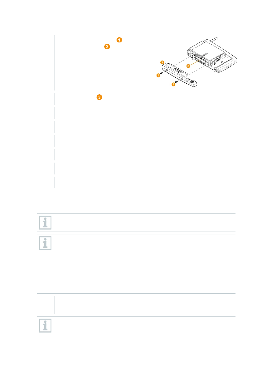
7 Maintenance
3
Undo screw connection and
4
Change battery .
5
Place the base plate on the Saveris base and screw it down.
6
Plug the Saveris base into the power supply.
7
Switch on Saveris base (hold down [ESC]).
8
Select the required language (press [Enter]).
1
Remove Saveris data logger from the wall bracket; see section 6.10.4.3
remove base plate from the Saveris
base.
Language selection appears.
Saveris base starts up and is ready for operation.
7.5.2 Changing the Saveris radio data logger batteries
Replace the batteries after 3 years of operation at the latest.
The battery life (with a measuring cycle of 15 minutes) is
• 3 years with standard AlMn batteries at +25°C and
• 3 years with Energizer batteries L91 photo lithium for freezer
applications (for operation below -10°C).
You can check the status of the Saveris data logger’s batteries via the
testo Saveris software. To do this, select the Saveris data logger you
would like to test under System | radio data logger. The current
charge status is displayed for you in the Battery status field.
Removing components from the wall bracket.
The Saveris data logger must be at room temperature when the
batteries are changed, as otherwise a build-up of moisture may impair
the measuring accuracy.
88
Page 89

7 Maintenance
2
Undo screws on the rear of the
3
Remove housing cover of the Saveris data logger .
4
Change batteries .
5
Place housing cover on the housing of the Saveris data logger.
6
Screw cover tightly onto the housing.
Unwanted residual discharge when disposing of old batteries.
Saveris data logger.
Ensure that you insert the batteries correctly.
The correct polarity is illustrated in the respective battery compartment.
A control switch is located in the housing which is actuated through the
cover. To this end, the cover must be screwed to the housing of the
Saveris data logger without any gap.
If the control switch is not actuated through the cover, the Saveris data
logger cannot be operated.
CAUTION
Mask the poles of the old batteries in order to prevent an unintended
residual discharge due to short-circuits during disposal.
Transport tip: If the Saveris data loggers are to be sent via air freight,
the batteries must be removed beforehand to avoid inadvertent radio
communication.
89
Page 90
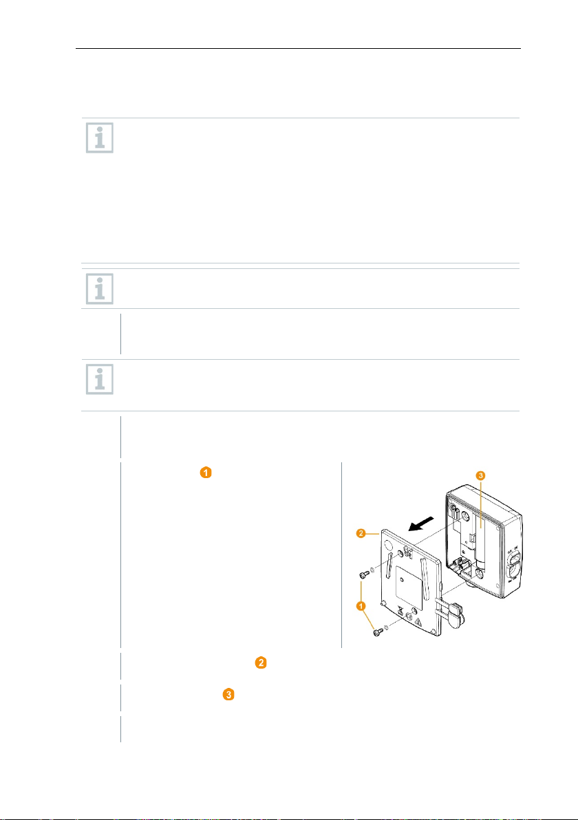
7 Maintenance
1
Remove component from the wall bracket; see section 6.10.4.3
y impair the measuring
2
3
Undo screws on the rear.
4
Remove housing cover .
5
Change batteries .
6
Place cover on the housing.
7.5.2.1 Changing the Saveris Ethernet data logger / Saveris analog coupler batteries
The batteries in the Saveris Ethernet data loggers and the Saveris
analog couplers are wearing parts which have to be replaced after
approx. 2 years.
In the event of a power failure, data loss cannot be ruled out for all
components.
As soon as a component's batteries are no longer fully functional, it
triggers a Defective battery system alarm.
The batteries (order no. 0515 5021) should then be replaced
immediately to ensure full functionality and data security.
While the batteries are being replaced, no readings can be recorded.
Removing components from the wall bracket.
The component must be at room temperature when the batteries are
changed, as otherwise a build-up of moisture ma
accuracy.
Disconnect the component from the power supply (mains plug / 24 V
AC/DC plug-in/screw terminal / Ethernet cable (PoE)).
90
Page 91

7
Screw cover tightly onto the housing.
8
Restore the power supply to the component (mains plug / 24 V AC/DC
• To make the most of the performance of the testo Saveris
• The Saveris measurement and configuration data are retained
If the storage path for your automated reports have been updated in
plug-in/screw terminal / Ethernet cable (PoE)).
Component is ready for operation.
A control switch is located in the housing which is actuated through the
cover. The cover must be screwed to the housing without a gap.
If the control switch is not actuated through the cover, the component
cannot be operated.
7.6 Update
measurement data monitoring system, the system should be
updated regularly.
• Software and firmware updates should always be carried out
together. In this respect, always begin with the software update for
updates to versions up to 4.2. Always begin with the firmware
7.6.1 Carrying out software update
update for updates to versions 4.3 and above.
7 Maintenance
during this process, as they are stored on the SQL Server®.
• If MAPI or SMTP Mail is installed, the settings should be
documented in the registry under
HKeylocalmachine\software\testo\comsoft\tdasmail and the email
components under software should be uninstalled before the
Saveris server uninstallation and reinstalled after the Saveris server
installation.
•
the registry, these settings should be updated again in the registry.
• After a testo Saveris CFR software update, the security settings in
the software must be reconfigured. To do this, please remove the
old configuration settings, close the software, open it again and
execute the security settings in the 3 Testo groups again.
Uninstall the older version of the Saveris Client (CFR version) without
uninstalling the database and then install the current server.
91
Page 92

7 Maintenance
1
In Windows, switch to System control - Programs and functions.
2
In Programs and functions, click on Testo Saveris Professional
3
Right mouse click and select Uninstall.
4
Confirm dialogue window with Yes.
5
Restart the PC.
1
Switch to the Testo Saveris Prerequisites directory on the Saveris
2
Run the setup.exe file.
3
Restart the PC.
1
Switch to the TestoSaverisServer directory on the Saveris CD or in the
2
Run the setup.exe file.
3
Restart the PC.
7.6.1.1 Uninstalling software
server.
The software is uninstalled
7.6.1.2 Installing software
CD.
Software has been updated.
If you are not carrying out the update from a CD but rather from a
downloaded directory, copy the TestoSaverisPrerequisites directly
under a root directory (e.g. C:\ or D:\) for this, so that the call-up path of
the setup file is as follows: C:\TestoSaverisPrerequisites or
D:\TestoSaverisPrerequisites.
7.6.1.3 Installing server
directory tree.
Server has been updated.
92
Page 93

exception of the Saveris cockpit unit) in your system to be automatically
7.6.2 Performing firmware system update
The firmware system update enables all Saveris components (with the
updated to the latest firmware version. This ensures that all
components in your system have the current firmware version.
Please note that a firmware update of Saveris cockpit units must be
Important information on the firmware system update
• Please note that two firmware system updates (V1.X and V2.X) are available
• The time taken for the firmware system update depends on the number of
• The Saveris base must be connected to the computer via USB or Ethernet
• All Saveris components must have at least firmware version 1.12 for the
• For an update to version 4.6 SP1, the components must have the following
carried out separately.
with the testo Saveris measurement data monitoring system.
First check exactly which firmware update is valid for your system. You can
check the compatibility of the firmware versions via the order number on
your Saveris base's type plate
o Firmware system update V1.X
valid for testo Saveris systems with Saveris base order no. 0572 0120,
0572 0121, 0572 0160, 0572 0161
o Firmware system update V2.X
valid for testo Saveris systems with base order no. 0572 0220, 0572
0221, 0572 0260, 0572 0261
Saveris components in the system. Automatic distribution of the firmware to:
o Saveris converters and Saveris extenders require at least 3 minutes
for the standard communication cycle + 2 minutes per component.
o Saveris Ethernet data loggers require at least 3 minutes for the
standard communication cycle + 2 minutes per component.
o Saveris routers require at least 6.5 hours (all registered routers are
updated in parallel).
o Saveris radio data loggers in stationary use require at least 16 hours
(all registered Saveris radio data loggers are updated in parallel).
cable.
update. System components with firmware version < V 1.12 can only be
updated via service interface.
firmware version as a minimum requirement:
o For V1.x systems: testo Saveris software 4.6 SP1, Saveris base and
Saveris radio data logger V1.90, Saveris router, Saveris converter and
Saveris extender V2.59, Saveris Ethernet data logger V1.47
o For V2.x systems: testo Saveris software 4.6 SP1, Saveris base and
Saveris radio data logger V2.59, Saveris router, Saveris converter and
Saveris extender V2.59, Saveris Ethernet data logger V1.47
7 Maintenance
93
Page 94
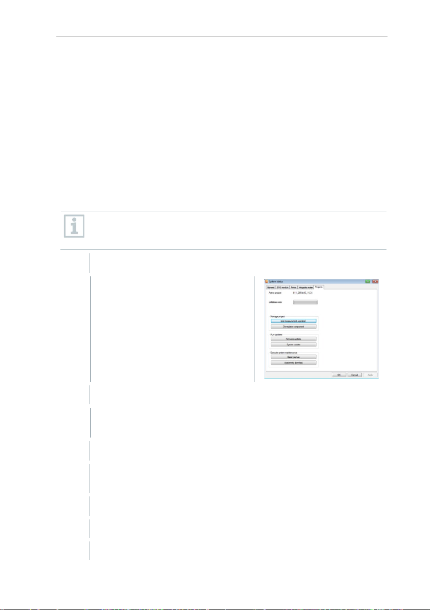
7 Maintenance
1
Unpack the firmware file folder and save it to your PC.
2
Open the Saveris Start-up Wizard
3
Select the destination directory where you saved the downloaded file
4
Confirm with [OK].
5
Confirm with [OK].
• You must acknowledge all outstanding alarms before a firmware system
update.
• ATTENTION: During the firmware update process, never disconnect the
power supply/network supply or the PC connection.
• During the update, measurements, data storage and data communication
are continued so there is no data loss.
• Configuration changes during the firmware system update should not be
carried out to ensure the process is not slowed down.
• Since there is heavy radio traffic during the update, alarms relating to
interrupted radio links may occur temporarily.
• Once a probe has been updated, the reboot phase takes approx. 1-2
minutes. During this brief time, no readings can be recorded.
Please note that the entire update process may take several hours.
During this time, no configuration changes or network/power supply
interruptions should occur.
and click on the System update
button in the Projects tab.
A Windows® Explorer Find folder window opens.
folder.
The process has been completed successfully message is
displayed after approx. 1 min.
The Saveris startup wizard closes automatically.
The firmware update for the Saveris base is installed.
94
Page 95
7 Maintenance
6
The update process is completed as soon as the Saveris base starts up
7
Select the language on the Saveris base and confirm this with [Enter]
7.1
Wait approx. 10 minutes until the Saveris base automatically
1
Plug the USB cable into the Saveris cockpit unit.
2
Press and hold down the Scroll up button on the Saveris cockpit unit.
3
Connect to a PC/notebook using the USB cable.
4
Release the Scroll up button on the Saveris cockpit unit.
again and Select language appears in the menu.
or
starts up.
The Saveris base firmware has been updated.
The update process for all other Saveris components in the system
begins.
After the system update, the new firmware version is shown for each
component in the Saveris software under the System menu item. The
firmware version view is only updated when the software is restarted.
7.6.3 Carrying out a testo Saveris cockpit unit firmware update
• Before a firmware update, all outstanding alarms must be acknowledged on
the Saveris cockpit unit.
• End any tours that are running on the Saveris cockpit unit.
• Disconnect the cockpit unit from the power supply and switch it off, or wait
until it switches off automatically.
Status LED on the Saveris cockpit unit lights up red.
The cockpit unit is displayed as a removable medium (FWUPDATE) in
Windows
®
Explorer.
95
Page 96

7 Maintenance
5
Open Windows® Explorer and click on FWUPDATE.
6
Remove the file included under FWUPDATE.
7
Switch to the destination directory where you saved the new firmware
8
Copy the new firmware file of the Saveris cockpit unit into the
file you downloaded.
FWUPDATE directory.
The Saveris cockpit unit firmware update is completed.
96
Page 97

8 Technical data
Memory
40,000 values per channel (total max.
18,000,000 values)
Dimensions
225 x 150 x 49 mm
Weight
Approx. 1510 g
Protection class
IP42
Housing material
Die-cast zinc / plastic
Radio frequency
868 MHz / 2.4 GHz
Power supply
6.3 V DC mains unit; alternatively via 24 V
consumption < 4 W.
Batteries
4
Li-ion rechargeable battery
supply during operation.
Operating temperature
+5 to +45°C
Storage temperature
-20 to +60°C
Display
Graphical LCD, 4 control keys
Interfaces
USB, radio, Ethernet
Max. 450 channels.
NC or NO contact
GSM module
850 / 900 / 1800 / 1900 MHz
Mounting
Table base and wall bracket included
8.1 testo Saveris base
Feature Value
AC/DC plug-in/screw terminals, power
The battery is used only for backing up data
and for an emergency SMS in the event of a
failure of the power supply, not for power
8 Technical data
Number of Saveris radio data
loggers
Alarm relay Max. 1 A, max. 30 W, max. 60/25 V DC/AC,
4
Wearing part
Max. 15 probes can be connected directly via
radio interfaces,
Max. 150 in total via radio / router / converter /
extender and Ethernet,
97
Page 98

8 Technical data
Housing dimensions
(W x H x D)
80 x 85 x 38 mm
Antenna length
81 mm
Weight
Approx. 220 g
Type of batteries
4 AA batteries
Battery life
Typical values with a 15-minute measuring
batteries for freezer applications
Housing material
Plastic
Radio frequency
868 MHz / 2.4 GHz
Measuring cycle
Standard 15 min (can be set from 1 min up to
24 h)
Storage temperature
-40 to +55°C (including batteries)
Display (optional)
2-line LCD; 7 segments with symbols
Approx. 100 m with no obstructions at 2.4 GHz
Wall bracket
Included
Probe type
NTC
Measuring range
-35 to +50°C
Accuracy
±0.4°C (-25 to +50°C)
± 0.8°C (remaining measuring range)
Resolution
0.1°C
8.2 Radio data loggers for testo Saveris
8.2.1 General
The technical data specified in the following table are valid for all Saveris radio
data loggers. Special data for the individual data logger types can be found in
the following sections.
Feature Value
cycle:
3 years at +25°C
3 years with Energizer L91 photo lithium
Transmission distance Approx. 300 m with no obstructions at 868
8.2.2 testo Saveris T1 / T1D
Feature Value
98
MHz,
Page 99

8 Technical data
Protection class
IP68
Conformity with standards
DIN EN 12830
Operating temperature
-35 to +50°C
Probe type (internal)
NTC
Measuring range (internal)
-35 to +50°C
Accuracy (internal)
±0.4°C (-25 to +50°C)
± 0.8°C (remaining measuring range)
Resolution (internal)
0.1°C
Probe type (external)
NTC
Measuring range (external)
-50 to +150°C
Accuracy (external)
±0.2°C (-25 to +70°C)
± 0.4°C (remaining measuring range)
Resolution (external)
0.1°C
Connection
NTC via mini-DIN socket, door contact
contact switch affects the service life.
Protection class
IP68 (with probe inserted or connection socket
sealed with rubber plug)
Conformity with standards
DIN EN 12830
Operating temperature
-35 to +50°C
Feature Value
8.2.3 testo Saveris T2 / T2D
Saveris radio data logger with external probe connection and internal NTC, door
contact.
Feature Value
connection cable included in the scope of
delivery (1.80 m). The setting of the door
99
Page 100

8 Technical data
Probe type
TC
Measuring range
TC type T
-200 to +400°C
Accuracy
±0.5°C or 0.5% of measured value (25°C)
Resolution
0.1°C / TC type S 1°C
Connection
2 TCs via TC socket,
max. difference in potential 2 V
Protection class
IP 54 (with probe inserted or connection socket
sealed with rubber plug)
Operating temperature
-20 to +50°C
Probe type
Pt100
Measuring range
-200 to +600°C
8.2.4 testo Saveris T3 / T3D
2-channel radio data logger with two external TC probe connections (TC
characteristics can be selected).
Feature Value
TC type J
TC type K
TC type S
-100 to +750°C
-195 to +1350°C
0 to +1760°C
The probe inputs are not galvanically isolated from one another. Take
this into account when using probes with a non-isolated thermocouple.
8.2.5 testo Saveris Pt / PtD
Radio data logger with an external Pt100 probe connection.
Feature Value
100
 Loading...