

TESTO Saveris T2 radio probe, Saveris T2D radio probe, Saveris T3 radio probe, Saveris T1 radio probe, Saveris T1D radio probe Instruction Manual
...Page 1

Measurement data monitoring with testo Saveris
Small Business Edition
Instruction manual
Page 2

2
Page 3

1 Contents
3
Pos: 1 /TD/Überschriften/1. Inhalt @ 0\mod_1 177587817070_79.d ocx @ 1243 @ 1 @ 1
1 Contents
1 Contents ................................................................................................... 3
2 Safety and the environment .................................................................... 7
2.1. About this document ........................................................................ 7
2.2. Ensure safety ................................................................................... 8
2.3. Protecting the environment .............................................................. 8
3 Specifications .......................................................................................... 9
3.1. Use .................................................................................................. 9
3.2. System requirements ..................................................................... 10
4 Product description ............................................................................... 12
4.1. Saveris base .................................................................................. 12
4.2. Saveris base GSM module (optional) ............................................ 14
4.2.1. Control keys ................................................................................................... 14
4.2.2. Displays ......................................................................................................... 15
4.3. Save radio probe ........................................................................... 21
4.3.1. Radio probe without display ........................................................................... 21
4.3.2. Radio probe with display ................................................................................ 22
4.3.3. Meaning of the LED displays at the probes .................................................... 23
4.4. Saveris Ethernet probes ................................................................ 24
4.5. Saveris router ................................................................................ 26
4.6. Saveris converter ........................................................................... 27
4.7. Saveris analog coupler .................................................................. 28
5 First steps .............................................................................................. 29
5.1. Flowchart ....................................................................................... 29
5.2. Inserting SIM card (optional) .......................................................... 31
5.3. Connecting USB cable to the Saveris base (optional) ................... 32
5.4. Connecting GSM antenna (optional) ............................................. 33
5.5. Connecting Saveris base with power supply ................................. 34
5.5.1. Power supply via mains unit ........................................................................... 34
5.5.2. Power supply via plug-in/screw connection (optional) .................................... 35
5.6. Inserting batteries in the probes .................................................... 36
5.7. Connecting radio probe ................................................................. 37
5.8. Installing Saveris software ............................................................. 39
5.9. Starting up hardware ..................................................................... 40
5.10. Starting Saveris software ............................................................... 42
Page 4

1 Contents
4
5.11.
Expand measuring system ............................................................ 44
5.11.1. Integrating a Saveris router (optional) ............................................................ 44
5.11.1.1. Connecting router with power supply (mains unit) ........................... 45
5.11.1.2. Connecting router with power supply (AC/DC) ................................ 46
5.11.1.3. Connecting router ............................................................................ 48
5.11.1.4. Assigning probes ............................................................................. 51
5.11.1.5. Connecting routers in series ............................................................ 53
5.11.2. Assigning an IP address to the Saveris base (optional) ................................. 57
5.11.3. Integrating Saveris Ethernet probe (optional) ................................................. 58
5.11.3.1. Connecting the network cable. ........................................................ 59
5.11.3.2. Connecting Ethernet probe with power supply (mains unit) ............. 60
5.11.3.3. Connecting USB cable and installing driver (optional) ..................... 61
5.11.3.4. Assigning connection data ............................................................... 62
5.11.3.5. Connecting the network cable to the Saveris base .......................... 64
5.11.3.6. Starting up Ethernet probes ............................................................. 65
5.11.4. Integrating Saveris converter (optional) ......................................................... 69
5.11.5. Integrating Saveris analog coupler (optional) ................................................. 70
5.12. Performing the test run ................................................................. 77
5.12.1. Checking system availability .......................................................................... 77
5.12.2. Testing the system ......................................................................................... 78
5.12.3. Checking alarm chain .................................................................................... 79
5.13. Mounting the hardware ................................................................. 79
5.13.1. Mounting the Saveris base on the wall .......................................................... 80
5.13.2. Setting up Saveris base with stand ................................................................ 82
5.13.3. Mounting the probe on the wall ...................................................................... 83
5.13.4. Checking the measuring system again .......................................................... 84
6 Using the product ................................................................................. 85
6.1. User interface ................................................................................ 85
6.2. Menus and commands .................................................................. 87
6.2.1. Start ............................................................................................................... 87
6.2.2. Edit ................................................................................................................ 88
6.2.3. Options .......................................................................................................... 90
6.2.4. Axes .............................................................................................................. 93
6.2.5. Template ....................................................................................................... 93
6.2.6. Selecting projects .......................................................................................... 93
6.2.7. Style template ................................................................................................ 93
6.3. Creating, editing and deleting zones ............................................. 94
6.3.1. Creating zones .............................................................................................. 94
6.3.2. Change zones ............................................................................................... 95
6.3.3. Deleting zones ............................................................................................... 95
6.4. Configuring the alarms .................................................................. 95
6.4.1. Basic settings for the SMS messages ............................................................ 96
6.4.2. Setting up base alarms .................................................................................. 98
6.4.3. Setting up alarm groups ................................................................................. 99
6.4.3.1. Components .................................................................................... 99
6.4.3.2. Channels ....................................................................................... 101
Page 5

1 Contents
5
6.5.
Analyzing series of measurements .............................................. 104
6.5.1. Diagram view ............................................................................................... 104
6.5.1.1. Enlarging the view ......................................................................... 104
6.5.1.2. Information on a reading (crosshairs) ............................................ 104
6.5.1.3. Showing regression curve ............................................................. 105
6.5.1.4. Text field ........................................................................................ 105
6.5.1.5. Characteristics of a curve .............................................................. 106
6.5.1.6. Settings for the axes in the diagram .............................................. 110
6.5.2. Table view ................................................................................................... 113
6.5.2.1. Marking readings ........................................................................... 113
6.5.2.2. Dropping the marking .................................................................... 114
6.5.2.3. Inserting extreme values or mean in the table ............................... 114
6.5.2.4. Compressing readings ................................................................... 114
6.5.2.5. Dropping compression ................................................................... 115
6.5.2.6. Determining largest reading ........................................................... 115
6.5.2.7. Determining the smallest reading .................................................. 115
6.5.2.8. Add rows ....................................................................................... 115
6.5.2.9. Compress ...................................................................................... 116
6.5.2.10. Drop compression ......................................................................... 116
6.6. Analyzing alarms ......................................................................... 116
6.6.1. Checking alarms .......................................................................................... 116
6.6.2. Acknowledge the alarm ................................................................................ 117
6.7. Creating evaluations .................................................................... 118
6.7.1. Printing measurement data .......................................................................... 118
6.7.2. Archiving with automatic reports .................................................................. 119
6.8. Checking the database capacity .................................................. 119
6.9. System settings ........................................................................... 121
6.9.1. General settings for the Saveris base .......................................................... 121
6.9.2. Show operating data of the probes. ............................................................. 122
6.9.3. Settings for the radio probe .......................................................................... 123
6.9.4. Ethernet probes ........................................................................................... 125
6.9.5. Analog coupler ............................................................................................. 127
6.10. Report settings ............................................................................ 128
7 Maintaining the product ...................................................................... 131
7.1. Maintenance ................................................................................ 131
7.2. Replacement of components ....................................................... 131
7.2.1. Deleting components ................................................................................... 131
7.2.2. Adding new components .............................................................................. 134
7.2.3. Logging components back in ....................................................................... 138
7.3. Calibration and adjustment .......................................................... 140
7.3.1. On-site calibration and adjustment ............................................................... 141
7.3.2. External calibration and adjustment ............................................................. 141
7.4. Saving data in the Saveris base .................................................. 142
7.5. Restarting the Saveris base ......................................................... 143
7.6. Removing probe from wall bracket .............................................. 144
7.7. Changing batteries at probe ........................................................ 144
7.8. Changing a battery ...................................................................... 146
Page 6

1 Contents
6
7.9.
Carrying out a software and firmware system update ................. 148
7.9.1. Carrying out a software update .................................................................... 149
7.9.1.1. Uninstalling software ..................................................................... 149
7.9.1.2. Software installation ...................................................................... 149
7.9.2. Carrying out a firmware system update ....................................................... 150
7.10. Technical data ............................................................................. 153
7.10.1. Saveris base ................................................................................................ 153
7.10.2. Saveris radio probe ...................................................................................... 154
7.10.3. Saveris router .............................................................................................. 161
7.10.4. Saveris Ethernet probes .............................................................................. 162
7.10.5. Saveris converter ......................................................................................... 168
7.10.6. Saveris analog coupler ................................................................................ 169
8 Tips and assistance ............................................................................ 172
8.1. Questions and answers .............................................................. 172
8.2. Saveris base alarm messages .................................................... 172
8.3. Accessories and spare parts ....................................................... 173
Pos: 2 /TD/--- Seitenwechsel --- @ 0\mod_1173774430601_0.docx @ 283 @ @ 1
Page 7
2 Safety and the environment
7
Pos: 3 /TD/Überschriften/2. Sic herheit und Umwelt @ 0\mod_11737747 19351_79.docx @ 292 @ 1 @ 1
2 Safety and the environment
Pos: 4 /TD/Überschriften/2.1 Zu diese m Dokument @ 0\mod_117377525 2351_79.docx @ 346 @ 2 @ 1
2.1. About this document
Pos: 5 /TD/Sicherheit und Umwelt/Zu diese m Dokument/Symbole und Sc hreibkonventionen/Sy mbole und Schreibkon v. [Saveris] @ 0\mod_1193 735939953_79.docx @ 562 3 @ 5 @ 1
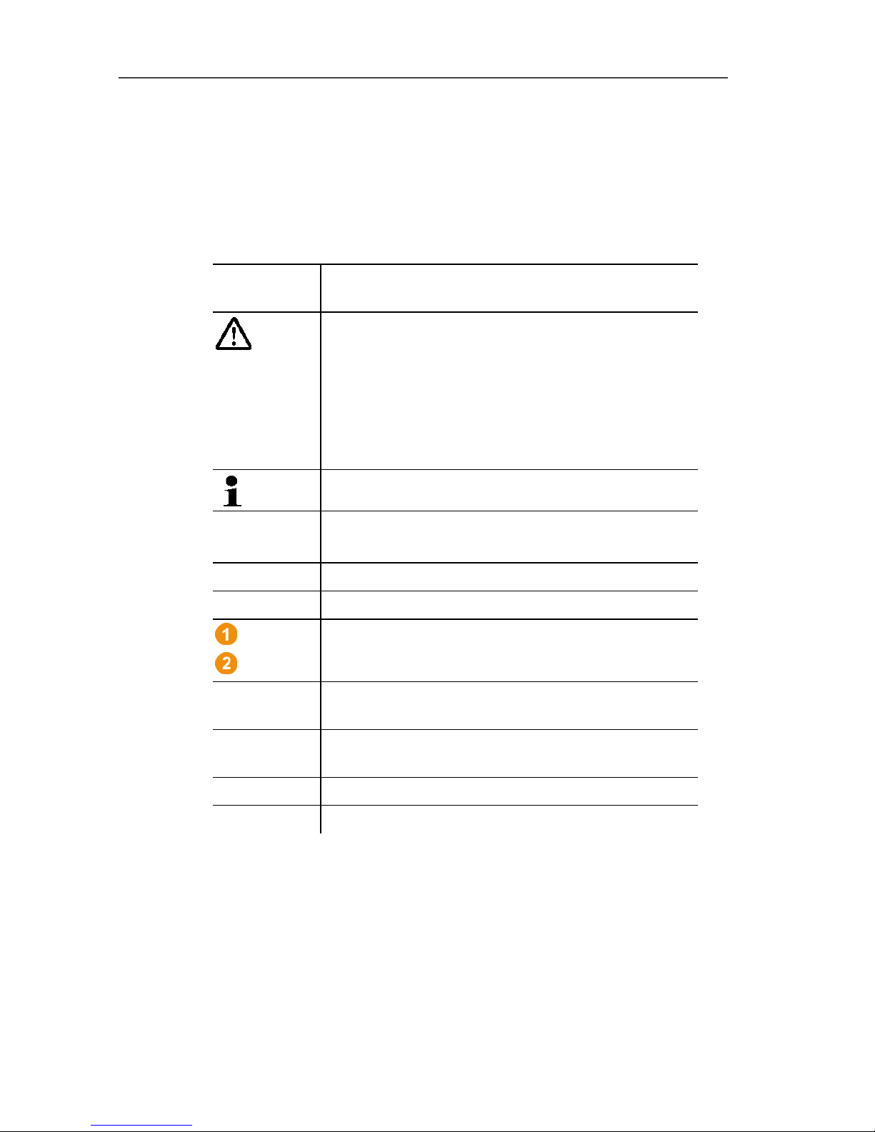
Symbols and writing standards
Representat
ion
Explanation
Warning advice, risk level according to the signal
word:
Warning! Serious physical injury may occur.
Caution! Slight physical injury or damage to the
equipment may occur.
> Implement the specified precautionary
measures.
Note: Basic or further information.
1. ...
2. ...
Action: more steps, the sequence must be
followed.
> ... Action: a step or an optional step.
- ... Result of an action.
...
...
Position numbers for the clarification of the
relationship between text and picture.
Menu Elements of the instrument, the instrument
display or the program interface.
[OK] Control keys of the instrument or buttons of the
program interface.
... | ... Functions/paths within a menu.
“...” Example entries
Pos: 6 /TD/Sicherheit und Umwelt/Zu diese m Dokument/Verwendung/Ver wendung (Saveri s) @ 0\mod_1191328770562_ 79.docx @ 5412 @ 5 @ 4
Use
> Familiarity with a PC as well as the Microsoft® products, is
assumed in this documentation.
> Please read this documentation through carefully and
familiarize yourself with the product before putting it to use. Pay
particular attention to the safety instructions and warning advice
in order to prevent injuries and damage to the products.
Page 8

2 Safety and the environment
8
> Keep this document to hand so that you can refer to it when
necessary.
> Hand this documentation on to any subsequent users of the
product.
Pos: 7 /TD/Überschriften/2.2 Sic herheit gewährleisten @ 0\mod_ 1173780783960_79. docx @ 366 @ 2 @ 1
2.2. Ensure safety
Pos: 8 /TD/Sicherheit und Umwelt/Sicher heit gewährleisten/Sa veris Wartungsar beiten @ 1\mod_11969586275 09_79.docx @ 6094 @ @ 1
> Carry out only the maintenance and repair work on the
components of the testo Saveris system that is described in the
documentation. Follow the prescribed steps exactly. Use only
original spare parts from Testo.
Pos: 9 /TD/Sicherheit und Umwelt/Sicher heit gewährleisten/Sa veris spannungsf ührende Teile @ 1\mod_12049 07008625_79.doc x @ 12630 @ @ 1
> Never use the Saveris probes to measure on or near live parts.
Pos: 10 /TD/Sicherheit und Umwelt/Sicher heit gewährleisten/ Produkt bestimmungs gemäß verwenden @ 0\mod_1173 781261848_79.doc x @ 386 @ @ 1
> Only operate the product properly, for its intended purpose and
within the parameters specified in the technical data. Do not
use any force.
Pos: 11 /TD/Sicherheit und Umwelt/Sicher heit gewährleisten/ Saveris Funk @ 1\mod_1198 149459718_79.doc x @ 6845 @ @ 1
> The output of the power supply for the Saveris probes, routers,
converters and the Saveris base is restricted in accordance with
EN 60950-1:2001. A manipulation of the power supply is not
allowed in terms of the radio authorization.
> The radio module is installed in the Saveris components such
that the limit values for air and creepage distance is adhered to
with regard to the standards. Changing the internal design of
the components is not allowed.
> When selecting the mounting location, ensure that the
permissible ambient and storage temperatures are adhered to
(see technical data).
At temperatures below 5 °C the rechargeable batteries
will not charge, within this temperature range secure
system operation is only possible to a limited extent.
Pos: 12 /TD/Überschriften/2.3 Umwelt sc hützen @ 0\mod_117378084 3645_79.docx @ 375 @ 2 @ 1
2.3. Protecting the environment
Pos: 13.1 /TD/Sicherheit und Umwelt/Um welt schützen/Akkus/ Batterien entsorgen @ 0\ mod_1175693637007_79. docx @ 619 @ @ 1
> Dispose of faulty rechargeable batteries/spent batteries in
accordance with the valid legal specifications.
Pos: 13.2 /TD/Sicherheit und Umwelt/Um welt schützen/Produk t entsorgen @ 0\mod_1173780 307072_79.doc x @ 357 @ @ 1
> At the end of its useful life, send the product to the separate
collection for electric and electronic devices (observe local
regulations) or return the product to Testo for disposal.
Pos: 14 /TD/--- Seitenwechsel --- @ 0\mod_1173774430601_0.docx @ 283 @ @ 1
Page 9
3 Specifications
9
Pos: 15 /TD/Überschriften/3. Leistungs beschreibung @ 0\mod_1 173774791554_79.d ocx @ 301 @ 1 @ 1
3 Specifications
Pos: 16 /TD/Überschriften/3.1 Verwendun g @ 0\mod_1176211016437_ 79.docx @ 695 @ 2 @ 1
3.1. Use
Pos: 17 /TD/Leistungsbeschreibung/Ver wendung/testo Sa veris/01 Einsatzgebie te @ 1\mod_119737644054 6_79.docx @ 6184 @ 5 @ 1
Areas of application
The testo Saveris measurement system can be used everywhere
where temperature and humidity-sensitive products are produced
and stored, for example in the food industry (cold rooms, deep
freeze rooms and refrigeration chambers), in smaller companies in
food production, as well as bakeries and butchers, or in the
pharmaceuticals industry (temperature-controlled cabinets, storage
of drugs).
But the measurement system can also be used in other industries
for monitoring the building air conditioning as well as for quality
assurance in store rooms for products in every phase of production.
The testo Saveris measurement system is only used to
monitor readings, not to control and regulate them.
The base with the SMS module may not be operated in
environments where, for example, the use of a mobile
phone is prohibited.
Pos: 18 /TD/Leistungsbeschreibung/Ver wendung/testo Sa veris/02 Funktionswei se @ 1\mod_1197376538421_ 79.docx @ 6194 @ 5 @ 1
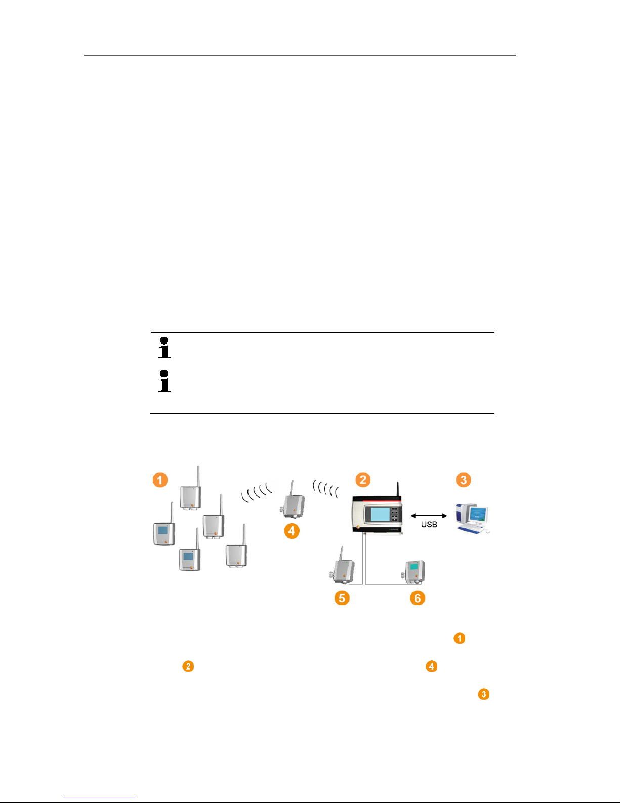
How it works
Pos: 19 /TD/Leistungsbeschreibung/Ver wendung/testo Saveri s/02b Funktionsweise SBE @ 1\ mod_1197980459890_79. docx @ 6553 @ @ 1
Pos: 20 /TD/Leistungsbeschreibung/Ver wendung/testo Sa veris/02c Funktions weise @ 1\mod_1197980516265 _79.docx @ 6573 @ @ 1
The ambient or process data for the temperature and air humidity in
closed rooms are measured and recorded using probes with the
measuring system. These readings are transmitted to the Saveris
base via radio, which then saves them. A router can be used
to optimize the radio in the event of difficult structural conditions.
The data are called up from the Saveris base by a computer and
saved in a database.
Page 10

3 Specifications
10
Very long distances can be bridged by using a converter that
converts the radio signals of the probe or router and then transmits
these measurement data to the base via Ethernet cable. In addition
the so-called Ethernet probes can be connected to the base
using an Ethernet cable.
With the testo Saveris software you thereby always have an
overview of the development of the readings in the individual areas.
Pos: 21 /TD/Leistungsbeschreibung/Ver wendung/testo Sa veris/04 Haftungsau sschluss @ 1\mod_119737661 6906_79.docx @ 6214 @ 5 @ 1
Exclusion of liability
The testo Saveris system was developed to consolidate a large
amount of measurement data from spatially separated probes in
the Saveris software, document it without interruption and issue
alarms in the event of irregularities.
The testo Saveris system is not designed to undertake control and
regulation tasks according to the regulations. Particularly the
alarms are not to be perceived as so-called critical alarms with
which the endangerment of life or limb or damage to equipment can
be averted.
Liability on the part of Testo AG for damages from this type of
application is excluded.
Pos: 22 /TD/Überschriften/3.2 Syste mvoraussetzungen @ 0\ mod_1187269645125_79. docx @ 2385 @ 2 @ 1
3.2. System requirements
Pos: 23 /TD/Leistungsbeschreibung/Sy stemvoraussetzun gen/Betriebssys tem (Saveris) @ 2\mod_120704 9498903_79.doc x @ 13979 @ 5 @ 4
Operating system
The software will run on the following operating systems:
• Windows® 7 SP1 64-bit/ 32-bit or later
• Windows® 8 64-bit/ 32-bit
• Windows® 8.1 64-bit/ 32-bit
• Windows® 10 64-bit/ 32-bit
• Windows® Server 2008 SP2 64-bit
• Windows® Server 2008 R2 64-bit
• Windows® Server 2012 64-bit
• Windows® Server 2012 R2 64-bit
Pos: 24 /TD/Leistungsbeschreibung/Sy stemvoraussetzun gen/Rechner (Saveri s) @ 0\mod_1191918060734 _79.docx @ 5433 @ 55 @ 4
Computer
The computer must meet the requirements of the corresponding
operating system. The following requirements must additionally be
fulfilled:
• 4.5 GB unused hard drive capacity with maximum size of the
database
• USB 2.0 interface
Page 11
3 Specifications
11
• Microsoft® Internet Explorer 9.0 or later
• Microsoft® Windows® Installer 4.5 or later
• Microsoft® .NET Framework 4.0 SP1 or later
• MDAC 2.8 SP1 or later
• Microsoft® Outlook® (only for MAPI installation)
The computer's processor, hard disk and interfaces
must be configured for continuous operation in order to
ensure smooth automatic operation. If necessary,
check your computer's energy-saving options.
If Windows® Installer, MDAC and .NET Framework are
not present on the computer, they will be installed with
the Saveris software. Restart after installation.
Date and time settings will be automatically accepted by
the PC. The administrator must make sure that the
system time is regularly compared with a reliable time
source and adjusted if necessary, to ensure authenticity
of the measurement data.
Database
• SQL Server® 2012 R2 Express is supplied.
• The Microsoft® versions SQL Server 2008, 2012, 2014 and
Terminal Server are supported.
Pos: 25 /TD/Leistungsbeschreibung/Sy stemvoraussetzun gen/Akku-Info ( Saveris) @ 14\mod_13732688245 88_79.docx @ 171823 @ 5 @ 4
Rechargeable battery
The battery in the Saveris base, the Ethernet probes and the
analog coupler is a wearing part, which has to be replaced after
approx. 2 years. If a battery is faulty, it is not possible to guarantee
full operability of the GSM module. In the event of a power failure,
data loss cannot be ruled out for all components. When a
component's battery is no longer fully functional, it triggers a
Defective battery system alarm.
The battery (article no. 0515 5021) should then be replaced
immediately to ensure full functionality and data security.
Pos: 26 /TD/--- Seitenwechsel --- @ 0\mod_1173774430601_0.docx @ 283 @ @ 1
Page 12
4 Product description
12
Pos: 27 /TD/Überschriften/4. Produkt beschreibung @ 0\mod_1173 774846679_79.doc x @ 310 @ 1 @ 1
4 Product description
Pos: 28 /TD/Produktbeschreibung/ Übersicht/testo Saver is/Hinweis CE @ 1\mod_120 4905902234_79.doc x @ 12612 @ @ 4
As declared in the declaration of conformity, this
product complies with Directive 2014/30/EC.
Pos: 29 /TD/Produktbeschreibung/Übersi cht/testo Saver is/00 Base/01 Base @ 0\mod_118 9504245140_79.doc x @ 4274 @ 255 @ 1
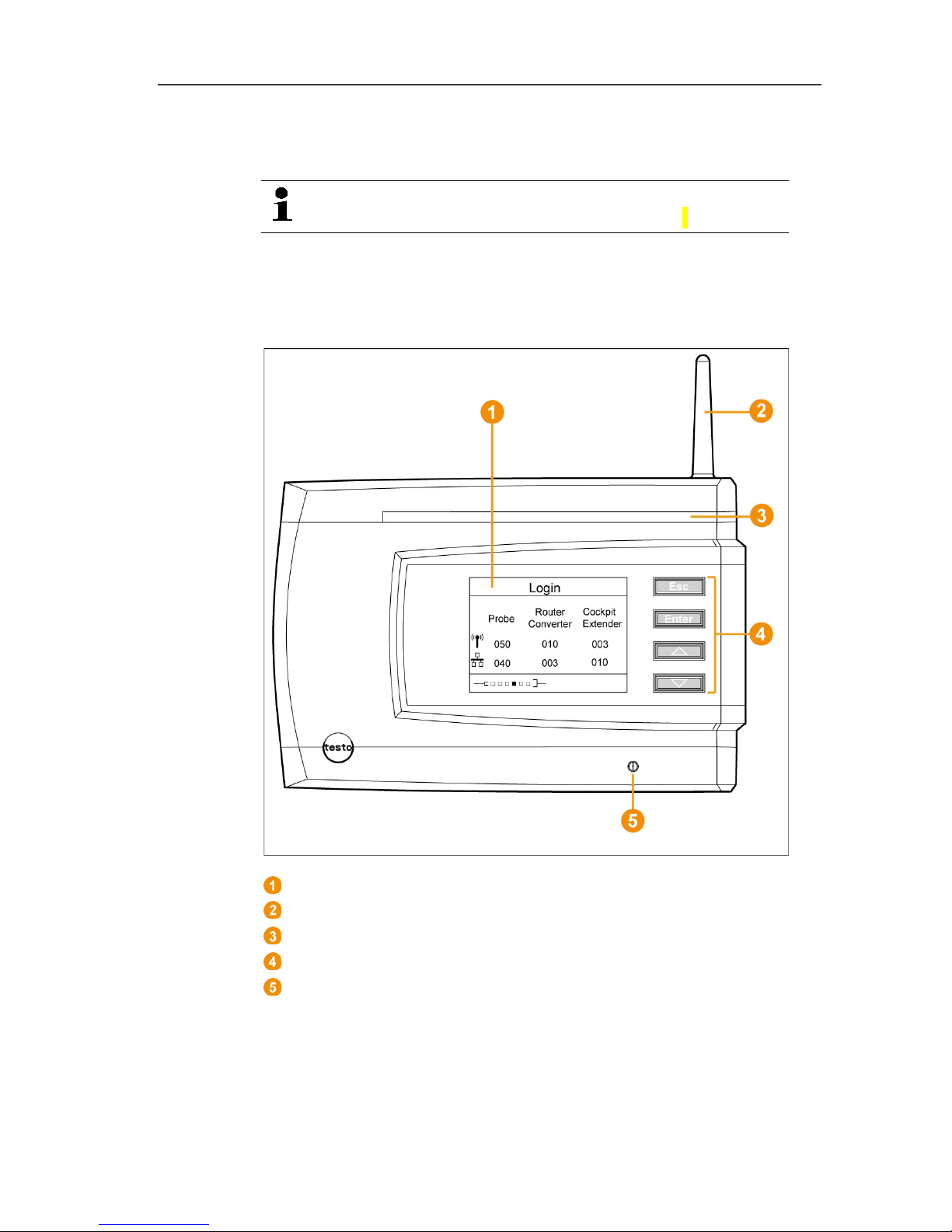
4.1. Saveris base
Front
Display for the visualization of the alarms and user guidance.
Antenna.
Warning LED
Keypad for operation of the Saveris base.
LED for status display.
Page 13
4 Product description
13
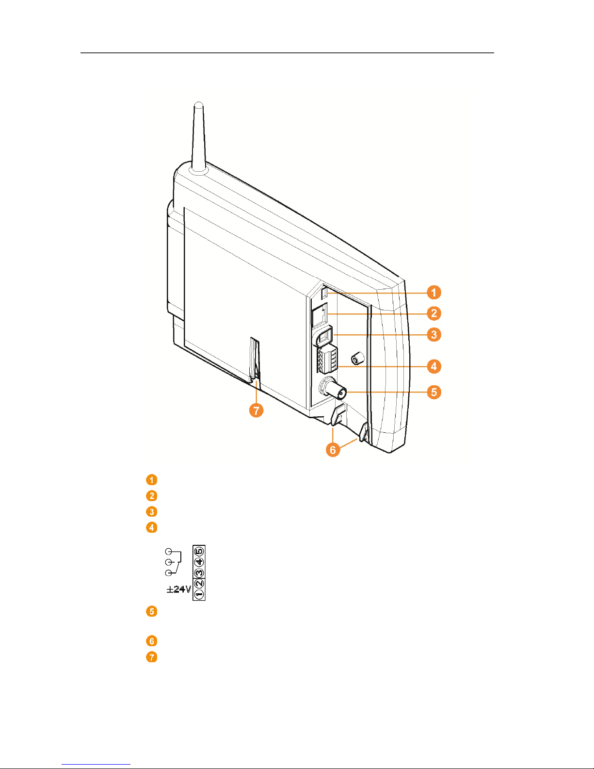
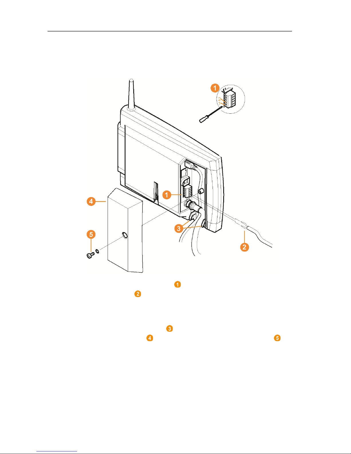
Rear
USB cable connection.
Network cable connection.
Connection of power supply via mains plug.
Connection of power supply via 24 V AC/DC and alarm relay.
Connection for external GSM antenna (only in combination with
GSM module).
Eyelets for strain relief.
Guide for stand or wall bracket.
Page 14
4 Product description
14
Pos: 30 /TD/Produktbeschreibung/ Übersicht/testo Saver is/00 Base/02 Base GSM @ 1\mod_1 196957066669_79.d ocx @ 6084 @ 3 @ 1
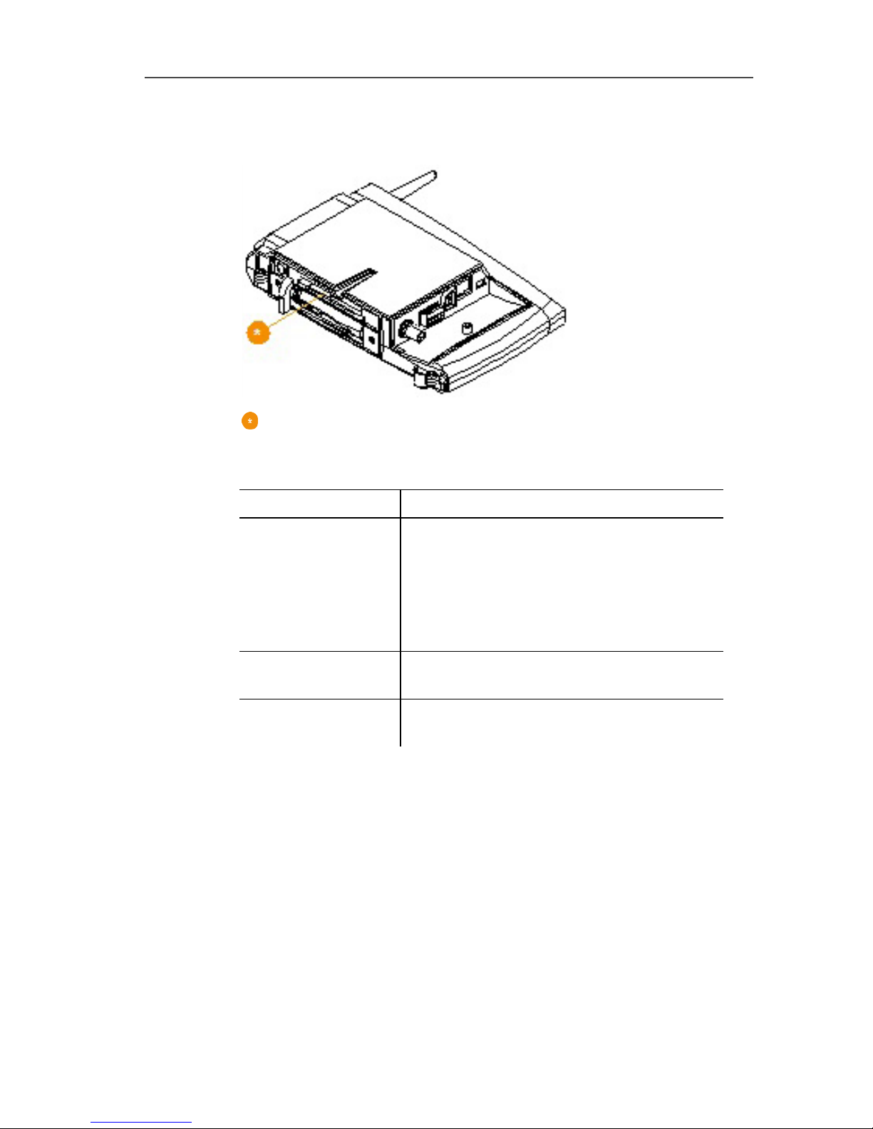
4.2. Saveris base GSM module (optional)
Insertion slot for the SIM card.
Pos: 31 /TD/Produktbeschreibung/ Übersicht/testo Saver is/00 Base/Bedienta sten @ 0\mod_1190205422 265_79.docx @ 4893 @ 3 @ 1
4.2.1. Control keys
Key Explanation
[Esc]
Switches from the Login menu to the
Info System menu.
In the Info Base menu, press [Esc]
briefly 2x: shuts down the Saveris base
Press and hold [Esc]: starts up the
Saveris base
[Enter]
In the Info System menu starts up the
login status for the probe.
[ ▲ ], [ ▼ ] Navigation buttons for changing the
menus.
Pos: 32 /TD/Produktbeschreibung/ Übersicht/testo Saver is/00 Base/Display anzeigen @ 0\mod_1190205 462296_79.docx @ 4902 @ 2 @ 1
Page 15
4 Product description
15
4.2.2. Displays
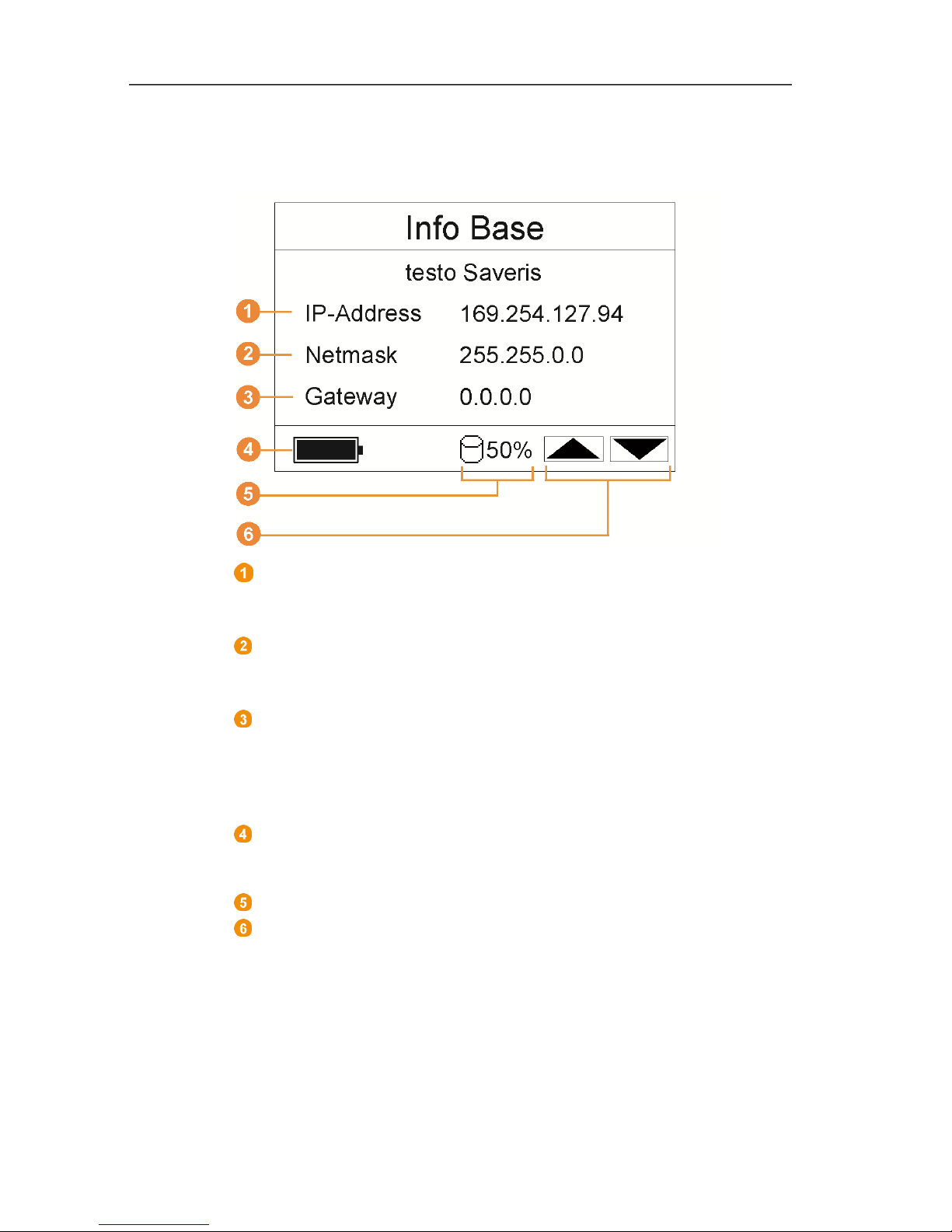
Info Base menu
IP address of the Saveris base.
The IP address is the unique identification number of the
Saveris base within the network.
Netmask that is saved in the Saveris base.
The netmask is the basic address of the network in which the
Saveris base is integrated.
Address of the gateway that is saved in the Saveris base.
A gateway is a transfer point between networks that work with
different protocols or data formats. A "translation" into the
respective other protocol or data format is then performed by
the gateway.
Fill level of the internal rechargeable battery in the event of
power failure. The display is only shown with an interrupted
power supply.
Fill level of the memory of the Saveris base.
Keys that are assigned functions in this menu.
Page 16
4 Product description
16
Info Alarm menu
Number of the newly triggered alarms.
Keys that are assigned functions in this menu.
New alarms have to be checked and acknowledged at
regular intervals. A large number (>100) of
unacknowledged alarms will impair the system
performance. The system automatically acknowledges
unacknowledged alarms once these number 200 or more.
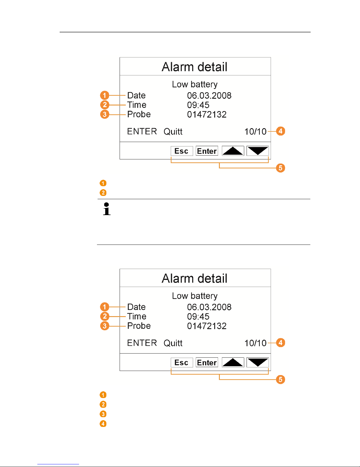
Alarm detail menu
Date on which the alarm was triggered.
Time at which the alarm was triggered.
Probe for which the alarm was triggered.
Number of the alarm and total amount of alarms.
Page 17
4 Product description
17
Keys that are assigned functions in this menu.
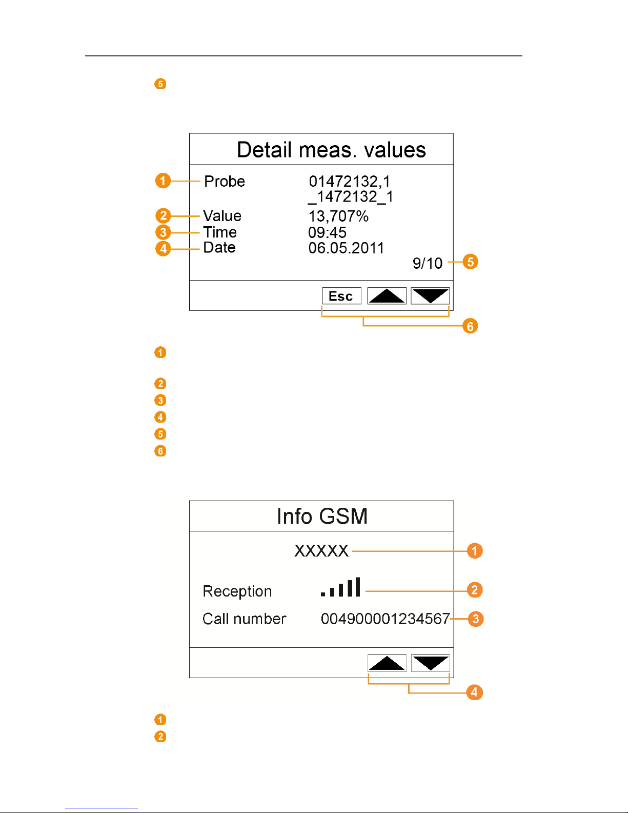
Reading detail menu
Probe and duct, if present, for which the reading was
transferred.
Reading with corresponding unit.
Time at which the reading was transferred.
Date on which the reading was transferred.
Number of the reading and total number of readings.
Keys that are assigned functions in this menu.
Info GSM menu
Name of the network operator.
Display of the reception quality.
Page 18
4 Product description
18
Telephone number that is saved on the SIM card.
Keys that are assigned functions in this menu.
Version number of the internal GSM module.
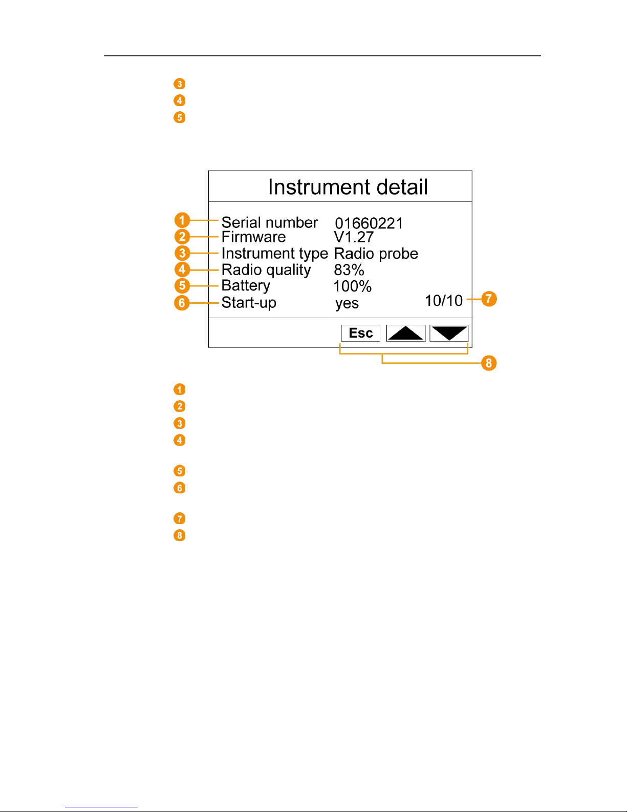
Instrument detail menu
Serial number of the connected instrument.
Firmware version of the connected instrument.
Type designation of the connected instrument.
Radio quality of the connected instrument (omitted for Ethernet
probes).
Battery status of the instrument (omitted for Ethernet probes).
Startup indicates whether the device has been configured by
the startup wizard.
Number of successful devices.
Keys that are assigned functions in this menu.
Page 19
4 Product description
19
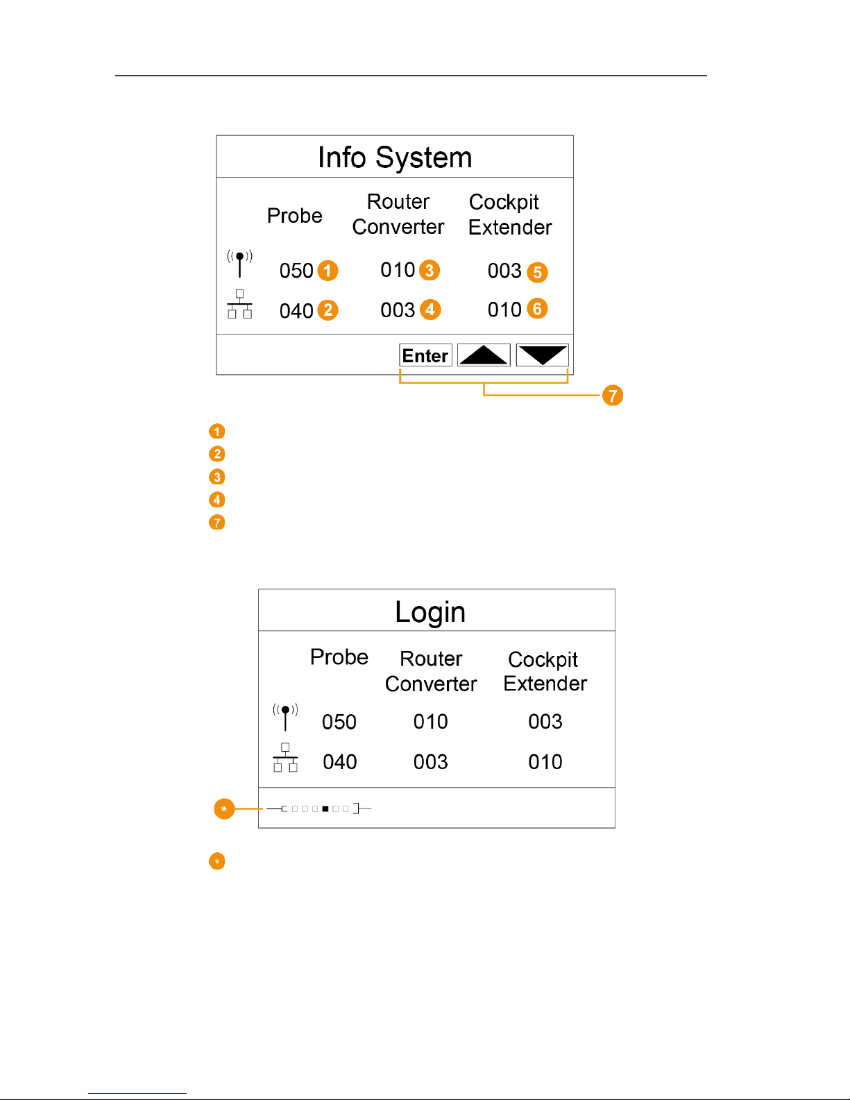
Info System menu
Number of connected radio probes.
Number of connected Ethernet probes.
Number of connected routers.
Number of connected converters.
Keys that are assigned functions in this menu.
Login 1/2 menu
Status display when probes are connected.
Page 20
4 Product description
20
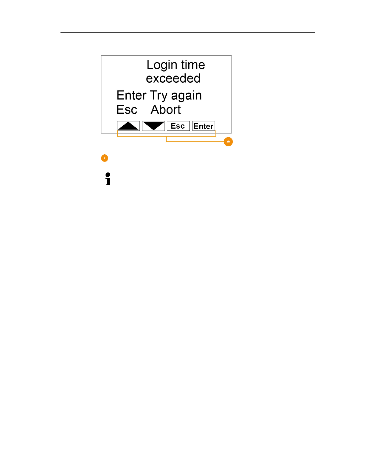
Login 2/2 menu
Keys that are assigned functions in this menu.
This display is shown if no login signal was received
from a probe within approx. 30 seconds.
Page 21
4 Product description
21
Pos: 33 /TD/Produktbeschreibung/Übersi cht/testo Saver is/01 Funkfühler/00 Fun kfühler @ 0\mod_11902 81497265_79.docx @ 5041 @ 3 @ 1
4.3. Save radio probe
Pos: 34 /TD/Produktbeschreibung/Übersi cht/testo Saver is/01 Funkfühler/01 Fun kfühler ohne Display @ 0\mod_1189496319546_79. docx @ 4255 @ 3 @ 1
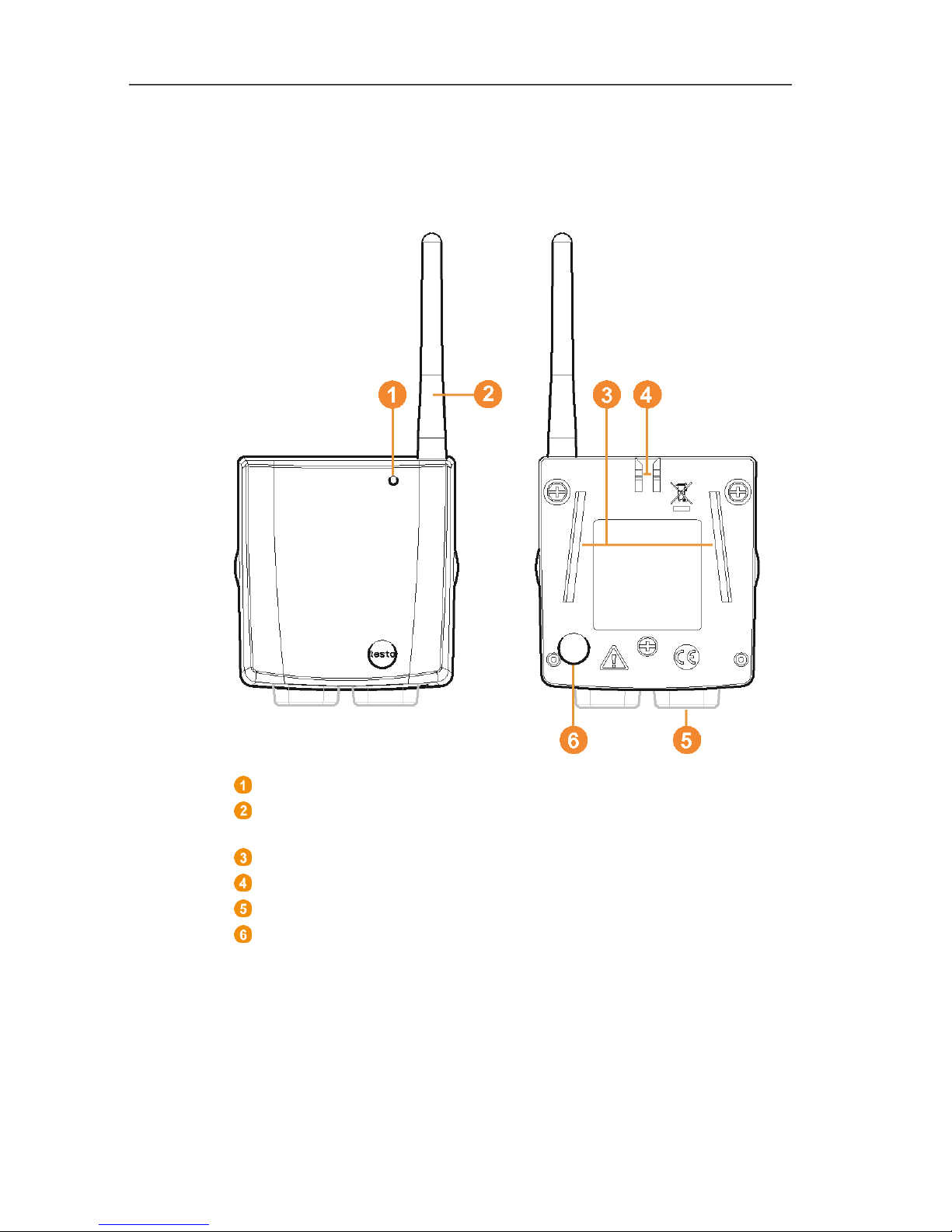
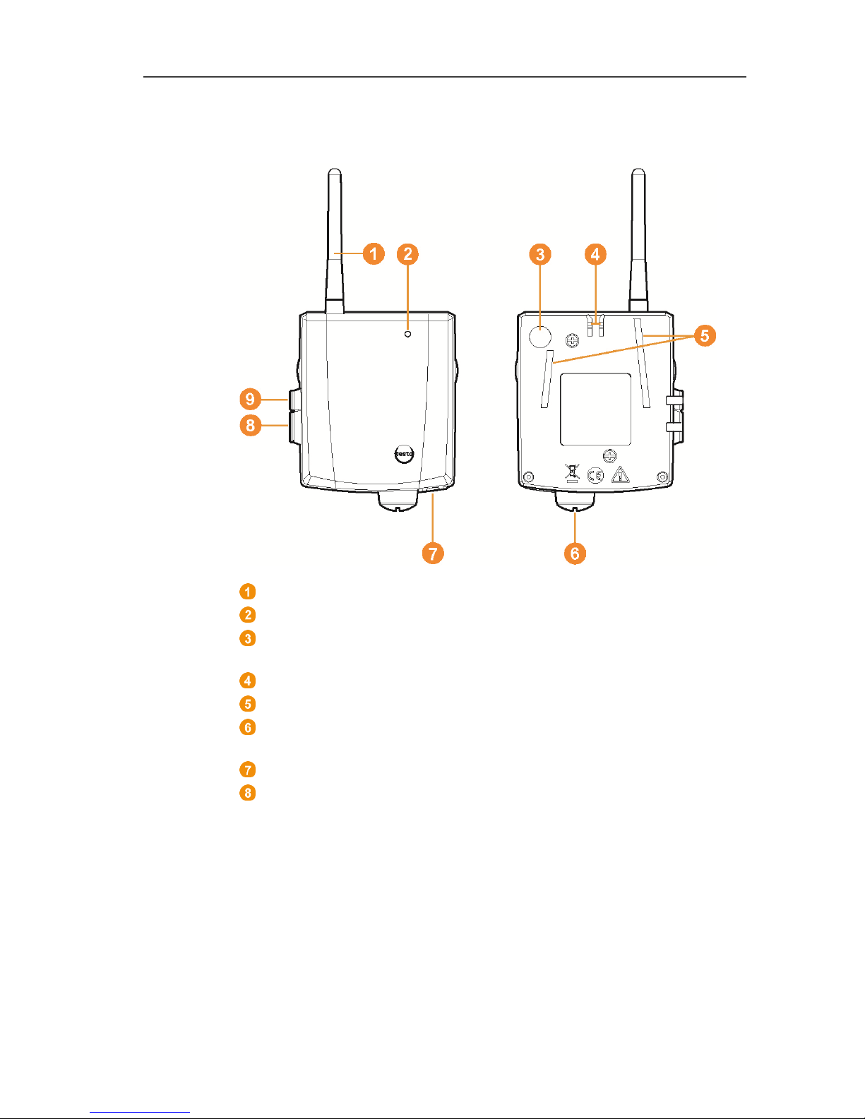
4.3.1. Radio probe without display
LED for status display.
Antenna for radio transmission of measurement data to the
Saveris base.
Guide rails for the wall bracket.
Catch for the wall bracket.
Ports, depending on type.
Connect button for connecting the probe to the Saveris base
and for a status request during operation.
Page 22
4 Product description
22
Pos: 35 /TD/Produktbeschreibung/Übersi cht/testo Saver is/01 Funkfühler/02 Fun kfühler mit Display @ 0\mod_1189496687343_79. docx @ 4264 @ 35 @ 1
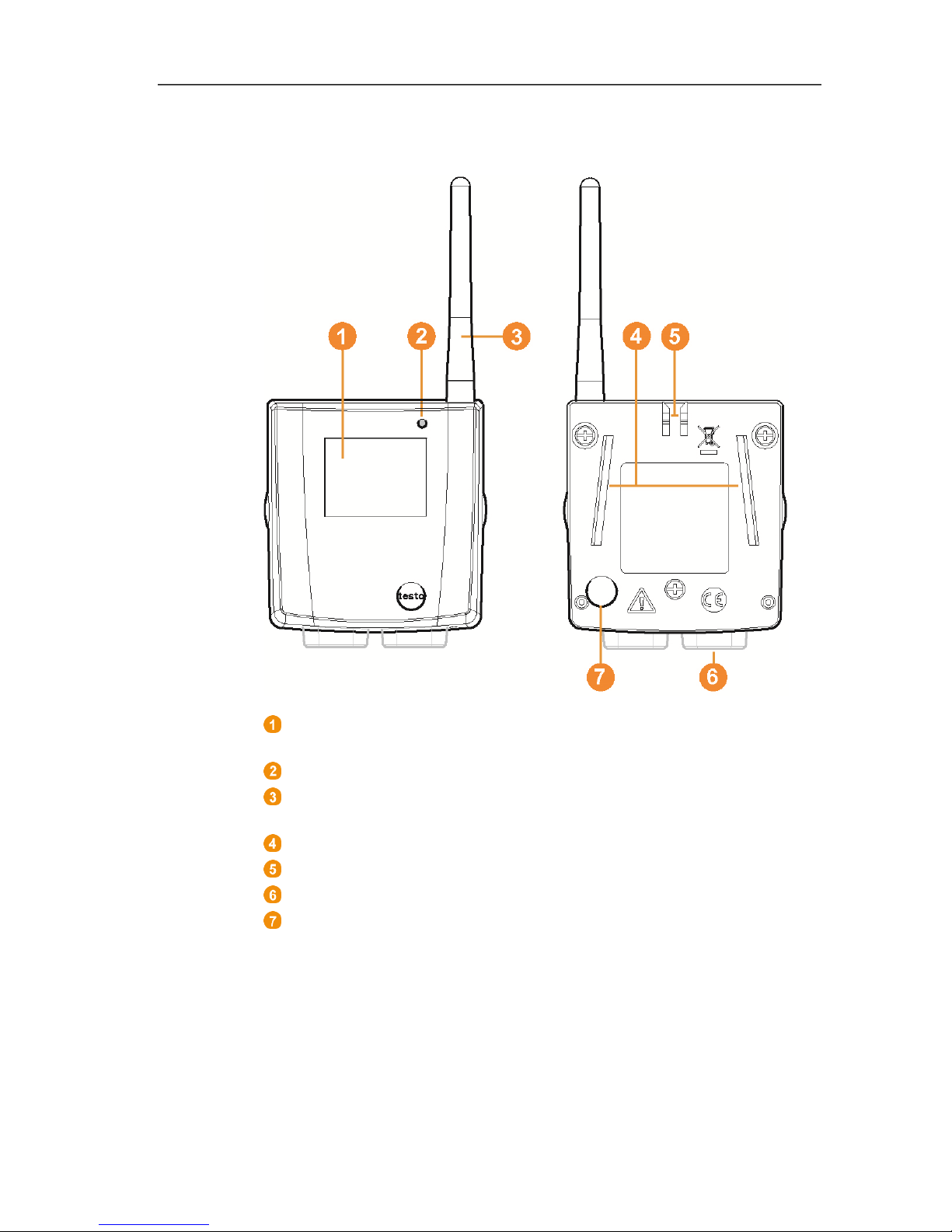
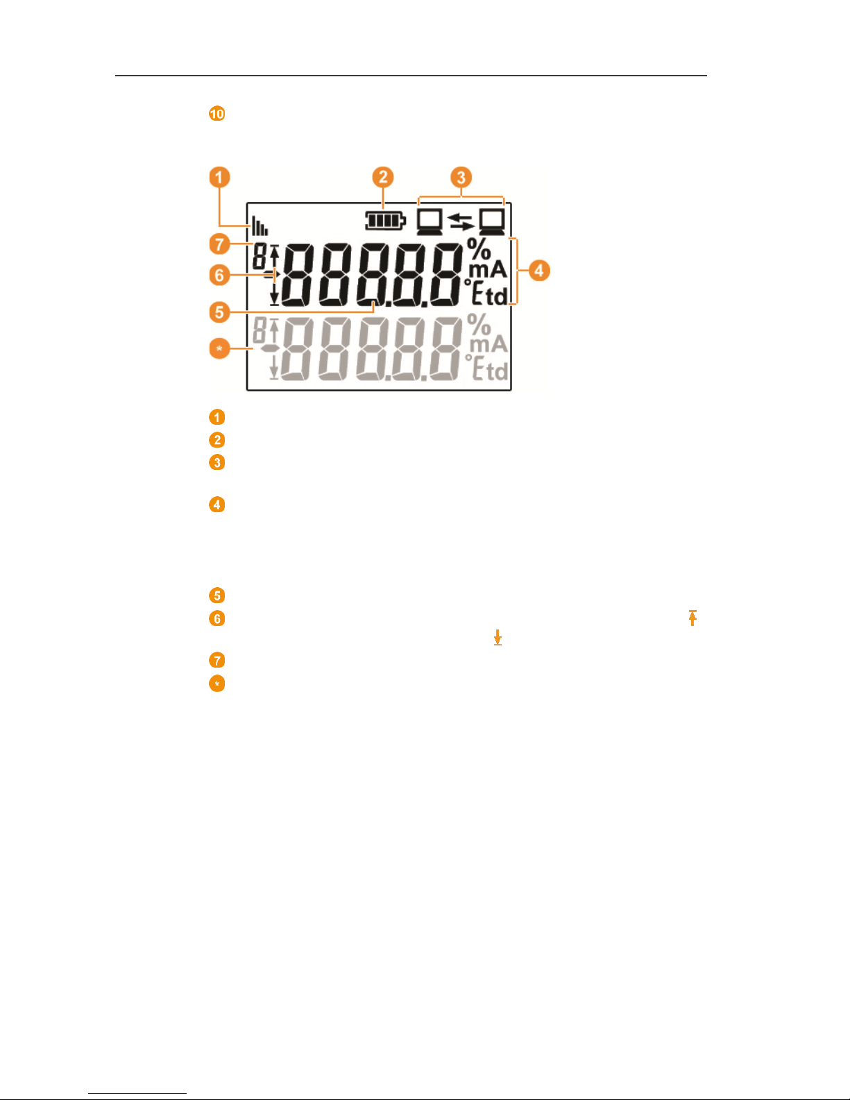
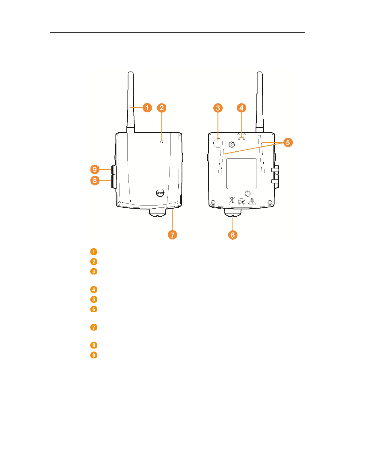
4.3.2. Radio probe with display
Display for showing reading, battery and connection status as
well as the field strength of the radio link.
LED for status display.
Antenna for radio transmission of measurement data to the
Saveris base.
Guide rails for the wall bracket.
Catch for the wall bracket.
Ports, depending on type.
Connect button for connecting the probe to the Saveris base
and for a status request during operation.
Page 23
4 Product description
23
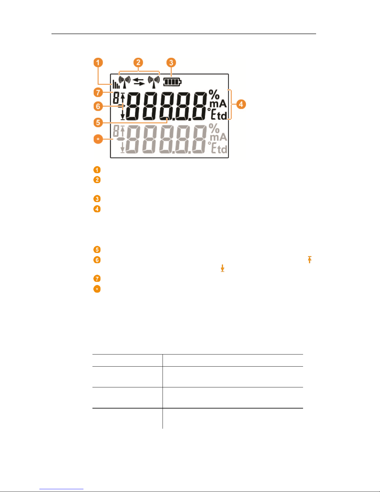
Displays
Quality of the radio link.
Indicator as to whether a communication with the Saveris base
or a router or converter is performed.
Battery status.
Unit of the reading:
• % for humidity measurement
• mA for current measurement
• °Ctd or °Ftd for dewpoint measurement.
Reading.
Indicator as to whether the reading has exceeded the upper ( )
limit value or undershot the lower ( ) limit value.
Number of the channel.
Display for a second sensor in the probe.
Pos: 36 /TD/Produktbeschreibung/Übersi cht/testo Saver is/01 Funkfühler/03 Bede utung der LED @ 0\mod_1190807 440000_79.doc x @ 5133 @ 255 @ 1
4.3.3. Meaning of the LED displays at the probes
Connecting to the Saveris base
Hold the connect button on the rear of the probe until the LED
begins to flash orange.
Representation Explanation
Flashing orange
An attempt to establish the connection to
the Saveris base.
Lit up green
The connection to the Saveris base was
performed successfully.
Lit up red
The connection to the Saveris base
failed.
Page 24
4 Product description
24
Status displays during operation
Briefly press the connect button on the rear of the probe once and
the LED shows the status of the connection to the Saveris base.
Representation Explanation
Flashing 3 x green
A very good connection to the Saveris
base exists.
Flashing 2 x green
A good connection to the Saveris base
exists.
Flashing 1 x green
A borderline connection to the Saveris
base exists.
Flashing 3 x red No connection to the Saveris base exists.
Pos: 37 /TD/Produktbeschreibung/Übersi cht/testo Saver is/02 Ethernet-Fühler /00 Ethernet-Fühl er @ 1\mod_119755572882 8_79.docx @ 6366 @ 5 @ 1
4.4. Saveris Ethernet probes
Pos: 38 /TD/Produktbeschreibung/Übersi cht/testo Saver is/02 Ethernet-Fühler /02 Ethernet-Fühl er @ 1\mod_119755573006 2_79.docx @ 6386 @ 2 @ 1
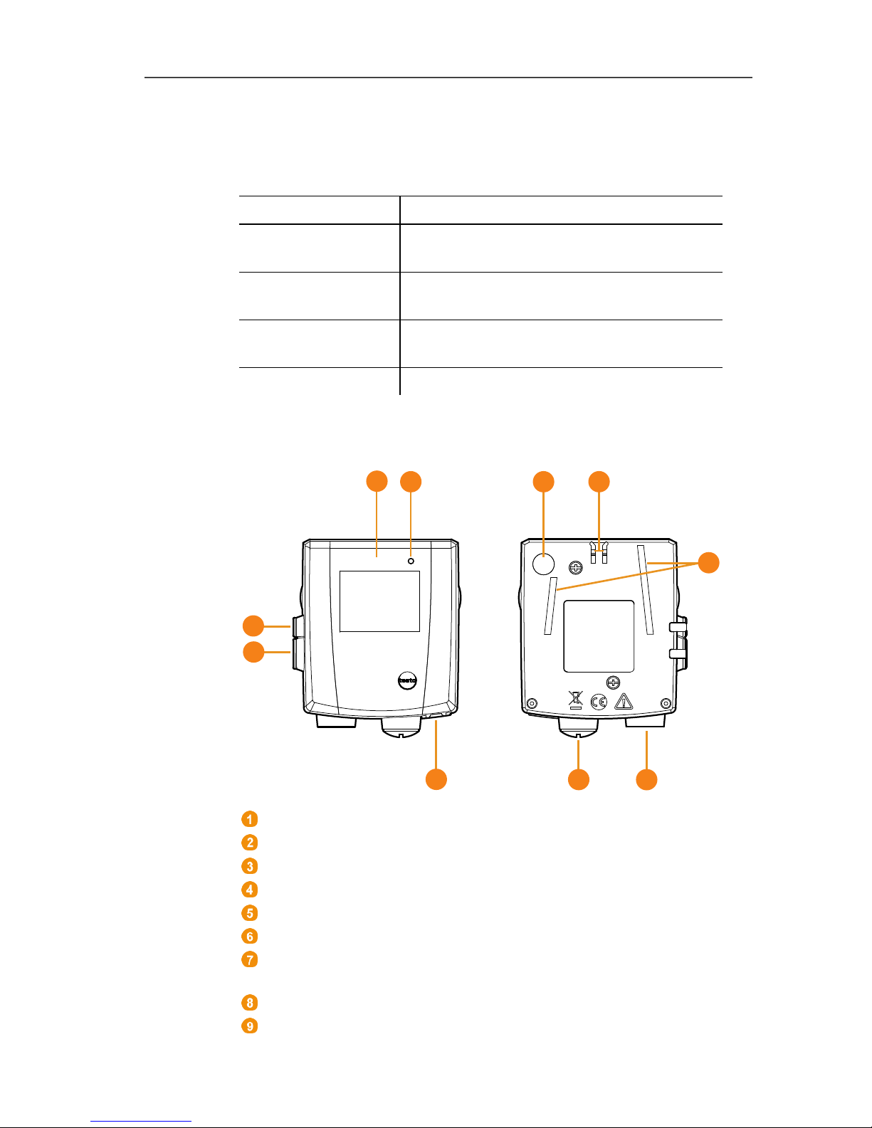
Display for showing the reading and transmission information.
LED for status display.
Connect button.
Catch for the wall bracket.
Guide rails for the wall bracket.
Input for external probes.
Input for external 24 V AC/DC power supply.
M1.6 x 1.5 cable coupling
Input for Ethernet interface.
Input for service interface.
1
2
3
8
9
10
7
4
5
6
Page 25
4 Product description
25
Input for power supply via mains unit.
Displays
Quality of the connection.
Battery status.
Indicator as to whether a communication with the Saveris base
is performed.
Unit of the reading:
• % for humidity measurement
• mA for current measurement
• °Ctd or °Ftd for dewpoint measurement.
Reading.
Indicator as to whether the reading has exceeded the upper ( )
limit value or undershot the lower ( ) limit value.
Number of the channel.
Display for a second sensor in the probe.
Page 26
4 Product description
26
Pos: 39 /TD/Produktbeschreibung/Übersi cht/testo Saver is/03 Router/01 Router @ 1\mod_1197555862937_ 79.docx @ 6406 @ 2 @ 1
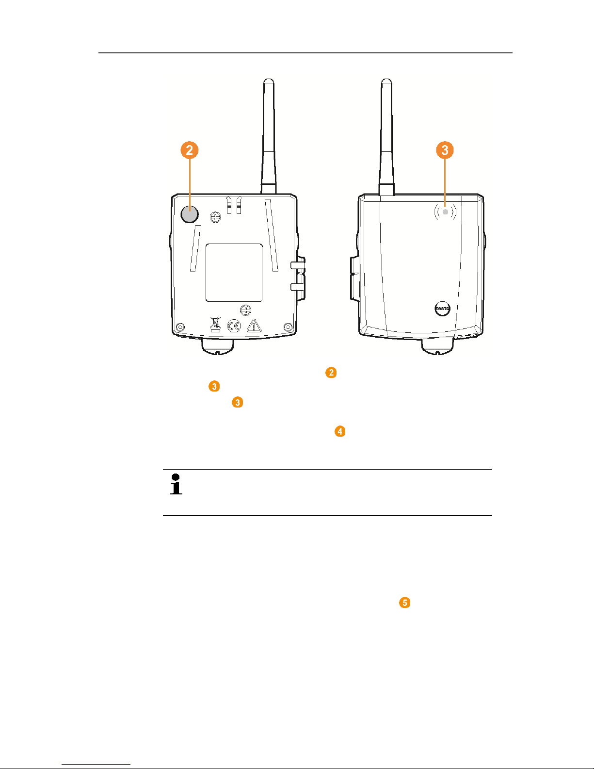
4.5. Saveris router
Antenna for the radio transmission of the measurement data
LED for status display
Connect button for connecting the router to the Saveris base
and for a status request during operation
Catch for the wall bracket
Guide rails for the wall bracket
Input for external 24 V AC/DC power supply.
M1.6 x 1.5 cable coupling
Input for service interface
Input for power supply via mains unit
Page 27
4 Product description
27
Pos: 40 /TD/Produktbeschreibung/Übersi cht/testo Saver is/04 Converter/ 01 Converter @ 1\mod_119755708 6312_79.docx @ 6416 @ 2 @ 1
4.6. Saveris converter
Antenna for receiving the measurement data.
LED for status display.
Connect button for connecting the converter to the Saveris base
and for a status request during operation.
Catch for the wall bracket.
Guide rails for the wall bracket.
Input for external 24 V AC/DC power supply.
M1.6 x 1.5 cable coupling
Input for connecting the network cable (optional power supply
via PoE).
Input for service interface.
Input for power supply via mains unit.
Page 28

4 Product description
28
Pos: 41 /TD/Produktbeschreibung/Übersi cht/testo Saver is/05 Analogkoppler /01 Analogkoppler @ 4\mod _1245762445743_79. docx @ 45338 @ 2 @ 1
4.7. Saveris analog coupler
Only with radio analog coupler U1: Antenna for sending the
measurement data.
LED for status display.
Connect button for connecting the analog coupler to the Saveris
base and for a status request during operation.
Catch for the wall bracket.
Guide rails for the wall bracket.
Cable coupling M16 x 1.5 for connecting to the transmitter.
Only with Ethernet analog coupler U1E: Input for connecting the
network cable.
Input for service interface.
Input for power supply via mains unit.
Pos: 42 /TD/--- Seitenwechsel --- @ 0\mod_1173774430601_0.docx @ 283 @ @ 1
Page 29
5 First steps
29
Pos: 43 /TD/Überschriften/5. Erste Sc hritte @ 0\mod_1173774895 039_79.docx @ 319 @ 2 @ 1
5 First steps
Pos: 44 /TD/Erste Schritte/testo Saveri s/00 Ablaufdiagra mm Inbetriebnahme @ 0\mod_1 189581707421_79.doc x @ 4454 @ 2 @ 1
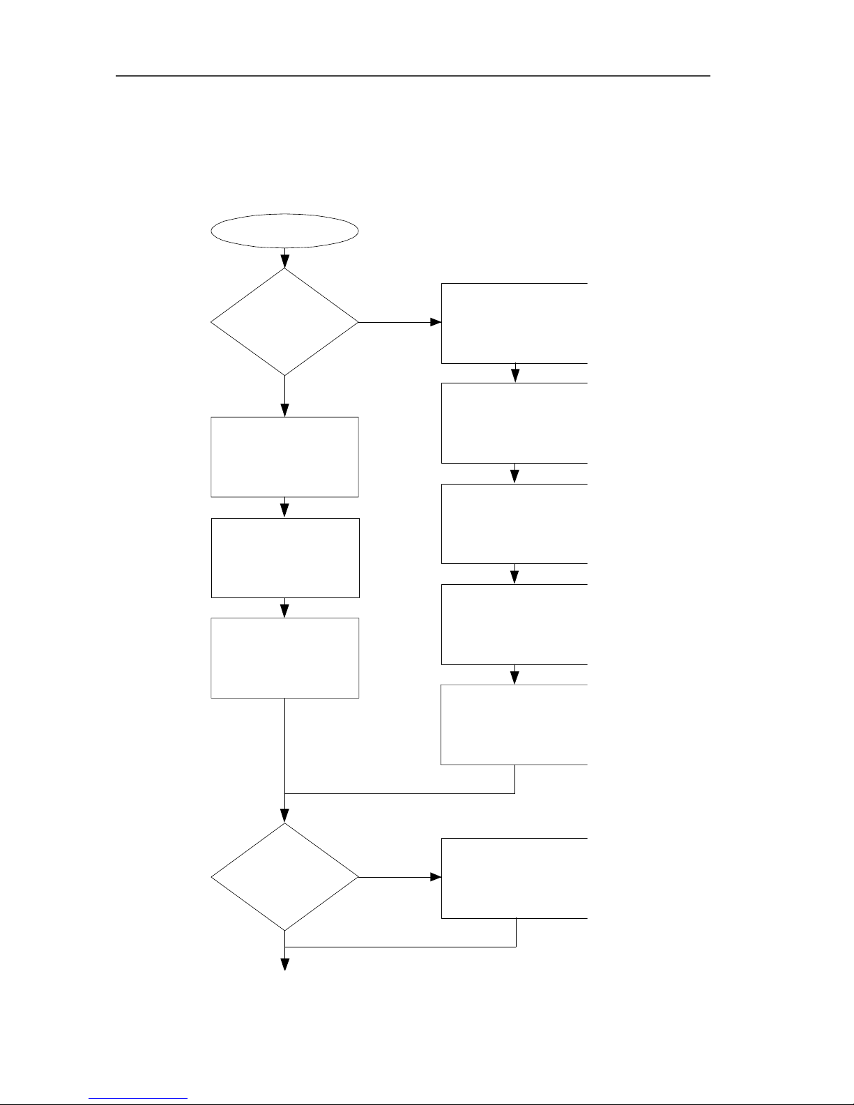
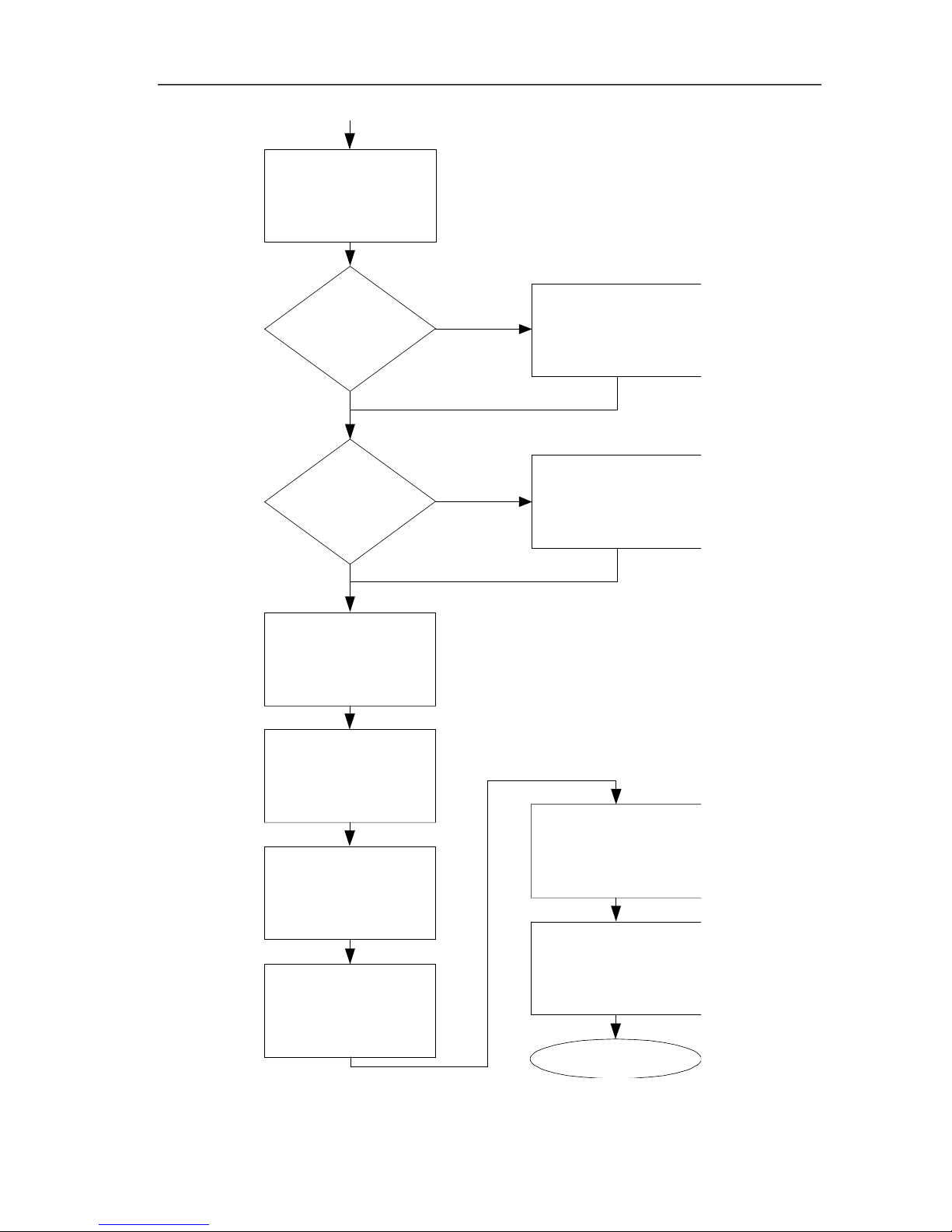
5.1. Flowchart
Start
Connecting USB cable
and
power supply to base
Connecting probe to
Saveris base
Use
router?
Integrating router
Base with
GSM module?
Inserting batteries
in probe
Inserting SIM card
Connecting USB cable
and
power supply to base
Connecting probe to
Saveris base
Inserting batteries
in probe
Connecting GSM
antenna
Page 30
5 First steps
30
End
Installing
software
Start up hardware
with the help of the
startup wizard.
Use
converter?
Yes
No
Integrating Ethernet
probe
Use Ethernet
probes?
Integrating converter
Starting
software
Performing
the test run
Mounting the
hardware
Yes
Creating zones
Configuring the
alarms
No
Page 31
5 First steps
31
Pos: 45 /TD/Erste Schritte/testo Saver is/00 SIM-Karte einse tzen @ 1\mod_119755731673 4_79.docx @ 6426 @ 2 @ 1
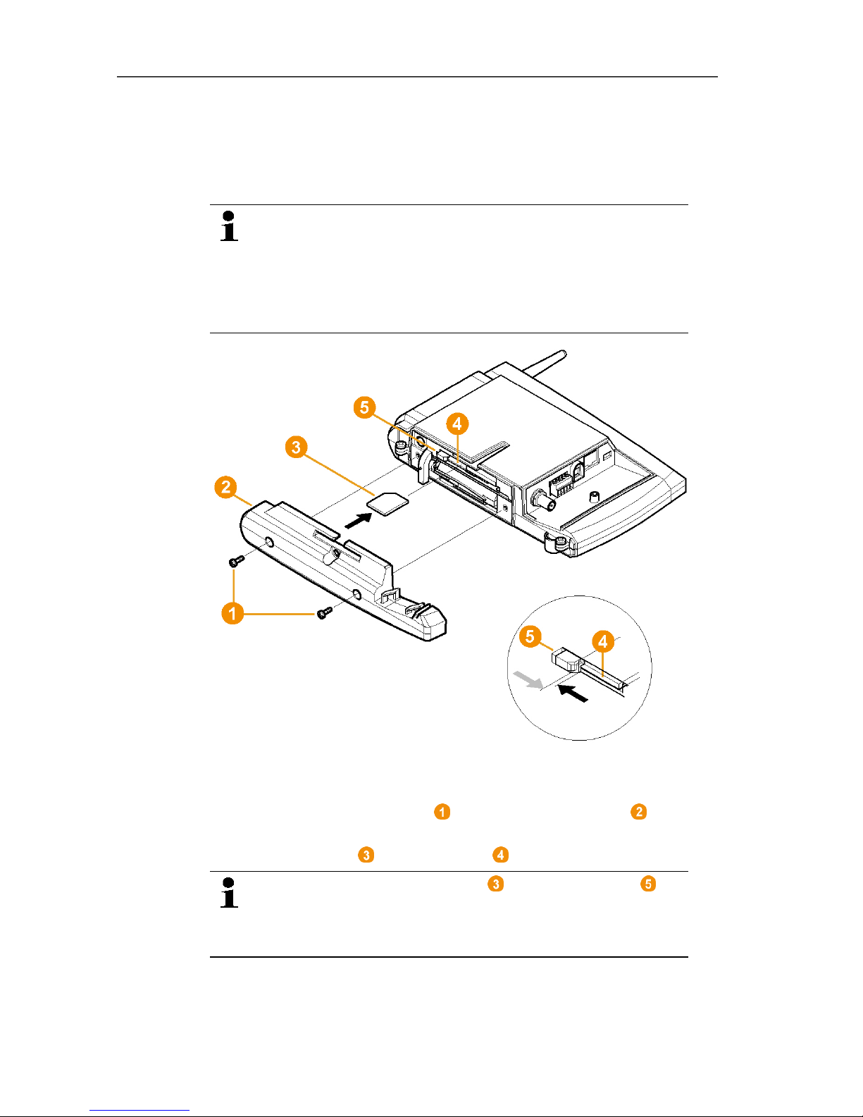
5.2. Inserting SIM card (optional)
With a Saveris base with integrated GSM module, you must insert
the SIM card.
The SIM card for sending SMS messages is not
included in the delivery and must be purchased
separately from a mobile phone provider.
It is recommended that you use a contract card instead
of a so-called prepaid card, as no alarm messages can
be sent if you use up your credit.
1. Switch off Saveris base (with Info Base view selected, briefly
press [ESC] twice).
2. Loosen screw connection and remove base plate from the
Saveris base.
3. Insert SIM card in the card slot as shown.
When inserting, the SIM card pushes the catch to
the side. If the card is inserted, a spring pushes the
catch back and the SIM card is thus secured in the card
slot.
4. Place the base plate on the base and screw it down.
Page 32
5 First steps
32
Pos: 46 /TD/Erste Schritte/testo Saveri s/01 USB-Kabel an Base ansc hließen @ 0\mod_11902 10196906_79.docx @ 4930 @ 2 @ 1
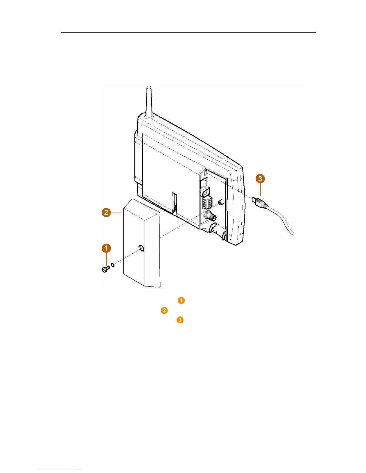
5.3. Connecting USB cable to the Saveris base
(optional)
1. Loosen and remove screw connection.
2. Remove cover from Saveris Base.
3. Plug the USB cable into the Saveris base.
Page 33

5 First steps
33
Pos: 47 /TD/Erste Schritte/testo Saveri s/01 Antenne anschließ en @ 1\mod_1197628729203 _79.docx @ 6463 @ 2 @ 1
5.4. Connecting GSM antenna (optional)
Pos: 48 /TD/Erste Schritte/testo Saveris/01b SBE Antenn e anschließen @ 1\mod_1 202123697639_79.doc x @ 8045 @ @ 1
Pos: 49 /TD/Erste Schritte/testo Saveri s/01c Antenne ansch ließen @ 1\mod_120212374209 3_79.docx @ 8056 @ @ 1
> Place antenna cable on the coaxial connection and screw
on .
Pos: 50 /TD/Erste Schritte/testo Saver is/02 Base mit Stromver sorgung verbinden @ 0\ mod_1188477940515_79. docx @ 2955 @ 3 @ 1
3
2
1
Page 34
5 First steps
34
5.5. Connecting Saveris base with power supply
You can connect the Saveris base to the power supply via the
included mains unit or via the 24 V AC/DC plug-in/screw terminal.
Pos: 51 /TD/Erste Schritte/testo Saver is/02a-1 Stromversor gung über Netzteil ver binden @ 0\mod_11913283 26843_79.docx @ 5392 @ 3 @ 1
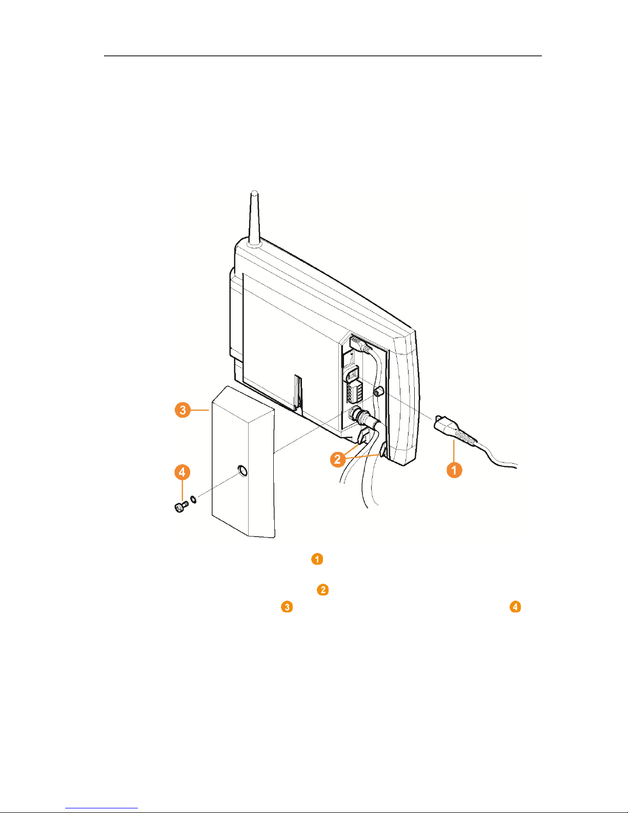
5.5.1. Power supply via mains unit
Pos: 52 /TD/Erste Schritte/testo Saveris/02a-2 SBE Str omversorgung über Netz teil verbinden @ 1\mod_1 200057993442_79.d ocx @ 7524 @ @ 1
Pos: 53 /TD/Erste Schritte/testo Saver is/02a-3 Stromversor gung über Netzteil ver binden @ 1\mod_12000580 46031_79.docx @ 7546 @ @ 1
1. Connect mains cable to the Saveris base.
2. Ensure that cabling cannot be pulled out using a cable tie at the
eyelets for strain relief .
3. Place the cover on the Saveris base and screw it down .
4. Connect mains plug to the power supply.
- The Saveris base automatically switches on after selecting the
language at the base and is ready for operation.
Page 35
5 First steps
35
Pos: 54 /TD/Erste Schritte/testo Saveri s/02b-1 Stromversor gung über AC/DC verbinde n @ 0\mod_1191328406187_7 9.docx @ 5402 @ 3 @ 1
5.5.2. Power supply via plug-in/screw connection
(optional)
Pos: 55 /TD/Erste Schritte/testo Saveris/02b-2 SBE Str omversorgung über AC/ DC verbinden @ 1\mod_1202124 389613_79.doc x @ 8067 @ @ 1
Pos: 56 /TD/Erste Schritte/testo Saveri s/02b-3 Stromversor gung über AC/DC verbinde n @ 1\mod_1202124473316_7 9.docx @ 8089 @ @ 1
1. Loosen clamping screws no. 1 and no. 2.
2. Insert cable in the terminals as shown.
Observe permissible operating voltage!
3. Tighten clamping screws.
4. Ensure that cabling cannot be pulled out using a cable tie at the
eyelets for strain relief .
5. Place the cover on the Saveris base and screw it down .
- The Saveris base automatically switches on after selecting the
language at the base and is ready for operation.
Page 36

5 First steps
36
Pos: 57 /TD/Erste Schritte/testo Saveri s/02 b Batterien am Fühler einlegen @ 0\mod_11913221 24515_79.docx @ 5263 @ 2 @ 1
5.6. Inserting batteries in the probes
1. Loosen screws on the rear of the probe.
2. Remove housing cover of probe .
3. Insert batteries .
Ensure that you insert the batteries correctly.
The correct polarity is illustrated in the respective
battery compartment.
4. Place housing cover on probe housing.
5. Screw cover down close to the housing.
A control switch is located in the housing that is
actuated through the cover. To do so, the cover must be
screwed to the probe housing without a gap.
If the cover is not screwed on without a gap, the probe
cannot be operated.
Transport note: If the probe is to be sent via air freight, the
batteries must be removed beforehand to avoid unintended
radio communication.
Page 37

5 First steps
37
Pos: 58 /TD/Erste Schritte/testo Saveri s/03 Fühler an der Base anme lden @ 0\mod_1188478029328 _79.docx @ 2964 @ 2 @ 1
5.7. Connecting radio probe
You can connect a maximum of 15 probes to the
Saveris base directly via radio.
In addition, you can operate 15 probes per converter
and 5 more probes per router or router cascade at the
Saveris base.
Note that a maximum of 450 channels can be
processed by the Saveris software.
1. Change to the Info System menu at the Saveris base with the
[▼] button.
2. Press [Enter] to call up the Login function.
- The status bar in the display shows that the Saveris base is
ready for probe detection.
Page 38

5 First steps
38
✓ With Saveris H2D/H4D radio probes, the external humidity
probe must be connected.
3. Hold down the connect key on the rear of the probe until the
LED at the probe begins to flash orange.
- The LED at the probe briefly turns green if this was detected
by the Saveris base.
The LED at the Saveris base briefly flashes green and a
prompt appears in the display of the base for the connection of
more probes or routers.
Multiple probes cannot be connected at the Saveris
base simultaneously. Multiple probes can only be
connected one after the other.
4. At the Saveris base, press the
• [Esc] key if no more components are to be connected.
- A note on the required performance of the startup assistant
is shown on the display for about ten seconds. Then the
Saveris base changes to the Info System menu in which
the number of connected components is now shown.
• Press [Enter] if further components are to be connected;
see previous step.
Page 39
5 First steps
39
5. Position the probes precisely at their measurement points to
check the radio link.
6. Briefly press the connect key on the rear of the probe.
If the LED at the probe flashes
• green, a radio link exists.
• red, no radio link exists.
If no radio link to the Saveris base exists even after a
change of location of the probe, connect a router to the
Saveris base; see Integrating a Saveris router
(optional), page 44.
Pos: 59 /TD/Erste Schritte/testo Saver is Inbetriebnahme/05a S averis-Software i nstallieren @ 1\mod_1 199789424718_79.doc x @ 6964 @ 2 @ 1
5.8. Installing Saveris software
> Before the installation: End all running programs, deactivate all
entries in the Autostart program group and restart PC.
Administrator rights are required for installation.
Log in directly as an administrator, not via Perform
as….
1. Insert CD with Saveris software in the CD-ROM drive.
If the installation program does not start automatically, open
Windows
®
Explorer and start the Setup.exe file on the CD.
Once you have received the installation file, e.g. via
e-mail, use the file Setup.exe at the highest level of the
installation disk.
2. Follow the directions of the installation wizard.
> After completing the installation, restart the computer and log in
with the same user name as before.
The USB driver for the connection of the Saveris base
is installed with the Saveris software.
If the Saveris base is not recognized as new hardware
when connected to the computer, the USB driver must
be manually installed.
Pos: 60 /TD/Erste Schritte/testo Saveris/04 Har dware inbetriebnehmen SBE @ 14\ mod_1380715780767_7 9.docx @ 177353 @ 2 @ 1
Page 40
5 First steps
40
5.9. Starting up hardware
Use the installation instructions when starting up the system for the
first time.
The following requirements must be fulfilled for the rest of the
startup process for the hardware:
• the Saveris base is ready for operation,
• all probes are registered on the Saveris base,
• the Saveris software is installed,
• a project has already been created and
• measurement operation has been ended.
1. Connect the Saveris base via the USB or network cable to the
computer on which the Saveris client is installed.
For continuous operation of the system, it is
recommended that the Saveris base be connected to
the computer via an Ethernet cable.
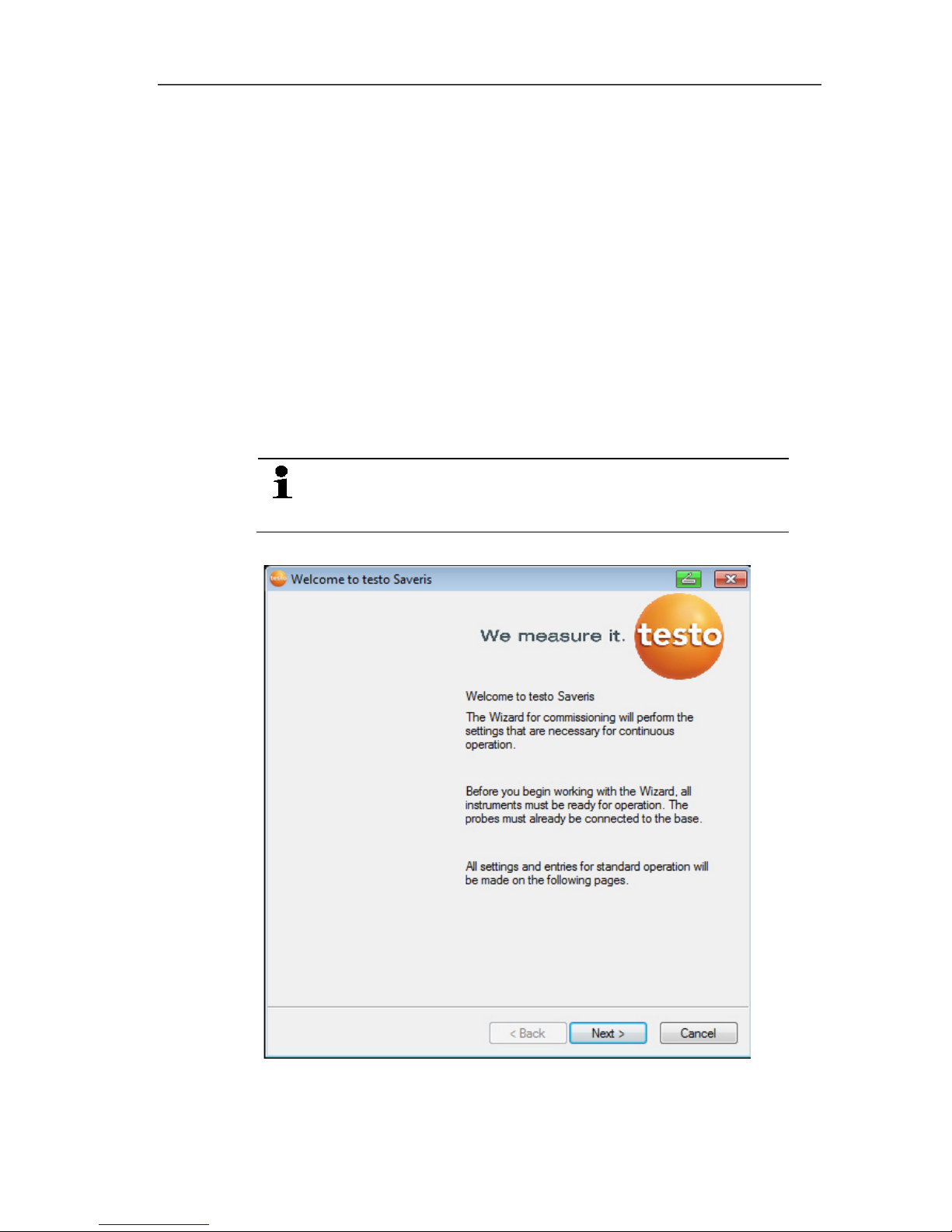
- The startup wizard starts.
2. Click on [Continue >].
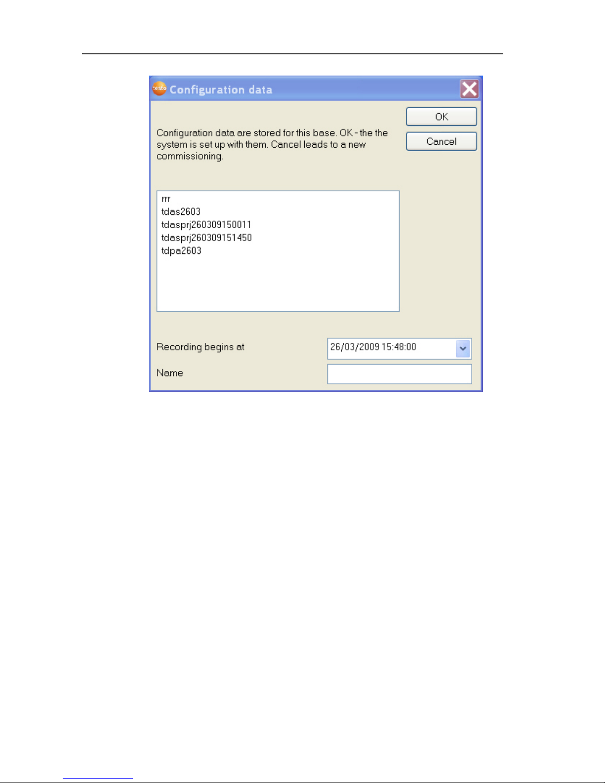
- The configuration data of the Saveris base are shown.
Page 41
5 First steps
41
3. Enter the project name in the Name field.
4. Determine which configuration data are to be used:
• Click on [Cancel] to reconfigure the project without using
predefined configuration data.
- Refer to installation instructions for information on
reconfiguring a project.
• Mark an existing project and click on [OK] to adopt the
configuration data of the marked project for the new project.
- The system settings of the Saveris base that are based on
the marked project are shown.
Page 42
5 First steps
42
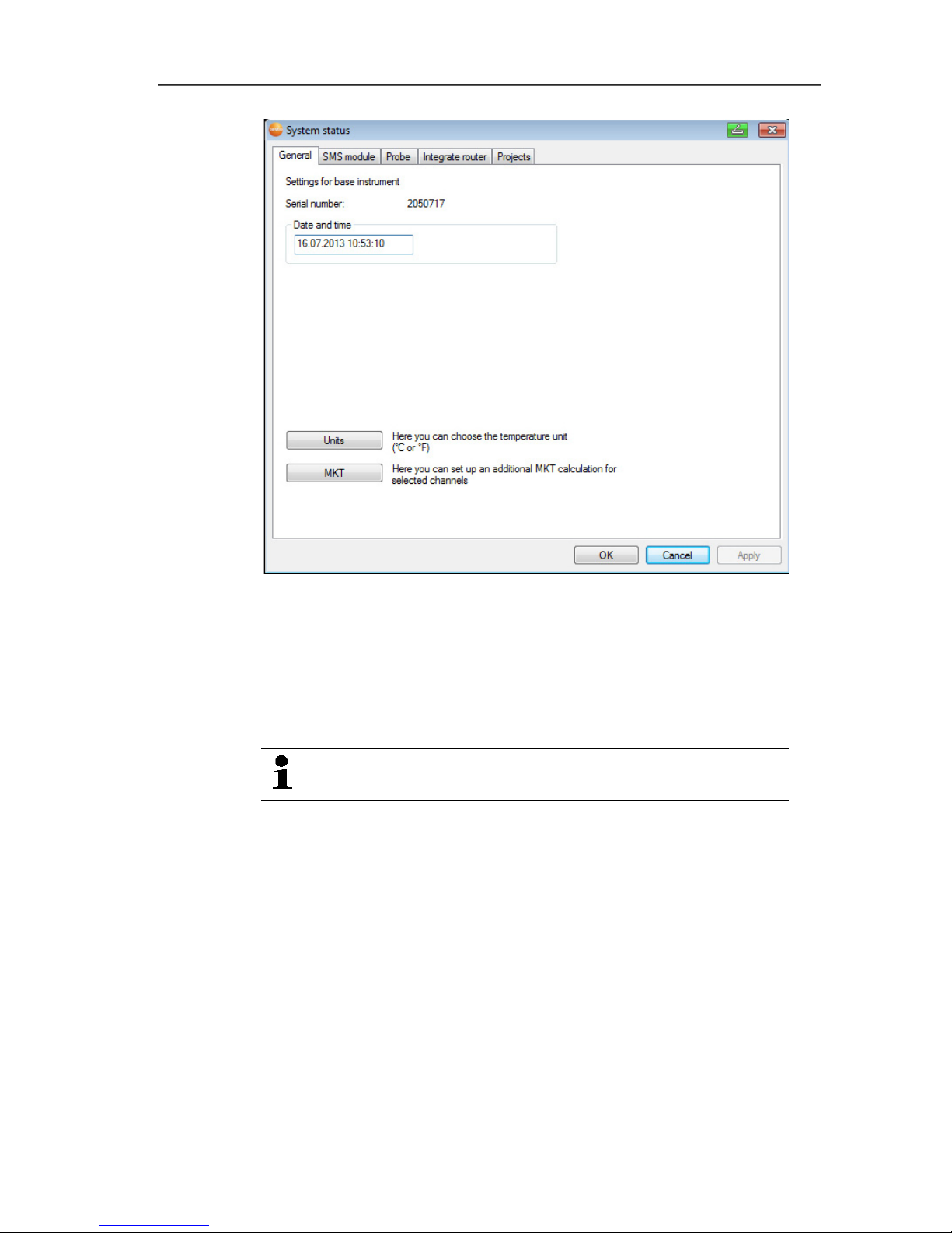
5. Click on [Units] to change the temperature unit for the system.
6. Click on [OK].
7. Make any further changes to the existing system settings as
required (see installation instructions).
Pos: 61 /TD/Produkt verwenden/testo Sa veris/01 Start/01_Sa veris-Software star ten @ 0\mod_1189076832593 _79.docx @ 3933 @ 2 @ 4
5.10. Starting Saveris software
Ensure that the Saveris software is not already open,
for example in multi-user operation under Windows® .
1. Select [Start] | All Programs | Testo | Saveris.
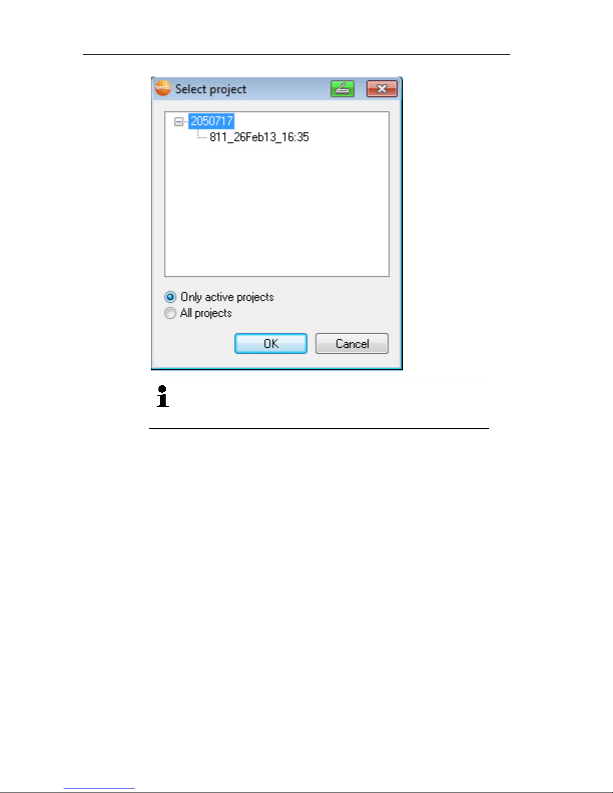
- The Testo Saveris software program window is opened with
the Select project dialogue.
Page 43
5 First steps
43
If the software will not start, check whether the testo
tdassvcs service is started in the service management
of the operating system and restart it, if needed.
2. Select the
• Only active projects option if the data from a running
project should be opened
• All projects option if the data from a completed project
should be opened.
3. Select the project that is to be opened in the tree structure.
4. Confirm with [OK].
- The Testo Saveris software program window is shown with
the selected data record in the foreground.
Pos: 62 /TD/Erste Schritte/testo Saver is/Hardware erwei tern/Messsystem erwei tern @ 1\mod_119755158 1796_79.docx @ 6327 @ 3 @ 1
Page 44

5 First steps
44
5.11. Expand measuring system
In this chapter, you learn how to integrate the Saveris router,
converter, Ethernet probes and analog coupler into the measuring
system.
Pos: 63 /TD/Erste Schritte/testo Saver is/Hardware erwei tern/01 a Router einbinden/ 00 Router einsetzen @ 1\ mod_1197549116203_79. docx @ 6304 @ 4 @ 1
5.11.1. Integrating a Saveris router (optional)
You can use a Saveris router to optimize radio communication
under poor structural conditions or to extend the radio path. The
router receives the signals of the radio probes and forwards them
to the Saveris base. Maximum extension of the radio path can be
achieved by connecting three routers in series.
The measurement data of up to five radio probes can
be transmitted per router or router cascade to the
Saveris base.
Up to 30 routers can be incorporated into the
measurement system. The Saveris base can
communicate directly with a maximum of 15 routers.
The integration of a router is performed in three steps:
1. Connecting the router to the power supply.
2. Registering the router on the Saveris base.
3. Assigning the radio probe to the router.
When positioning a router, please note the following
points:
• When integrating several probes via a router, the
probe with the weakest radio link determines the
position of the router.
Mount the router in such a way that this probe has
an ideal radio link.
• Probes and router should be mounted so that the
antennas are pointing upwards.
• The radio link between probes and the router, as
well as the router and the Saveris base, should not
be strongly influenced by structural conditions
(walls, shelves, etc.).
Mount the router and probe so that "visual contact"
exists with as many radio links as possible.
Page 45

5 First steps
45
Pos: 64 /TD/Erste Schritte/testo Saveri s/Hardware erwei tern/01 a Router einbinden/ 01 Router-Strom @ 1\mod_11 97548324640_79.doc x @ 6294 @ 4 @ 1
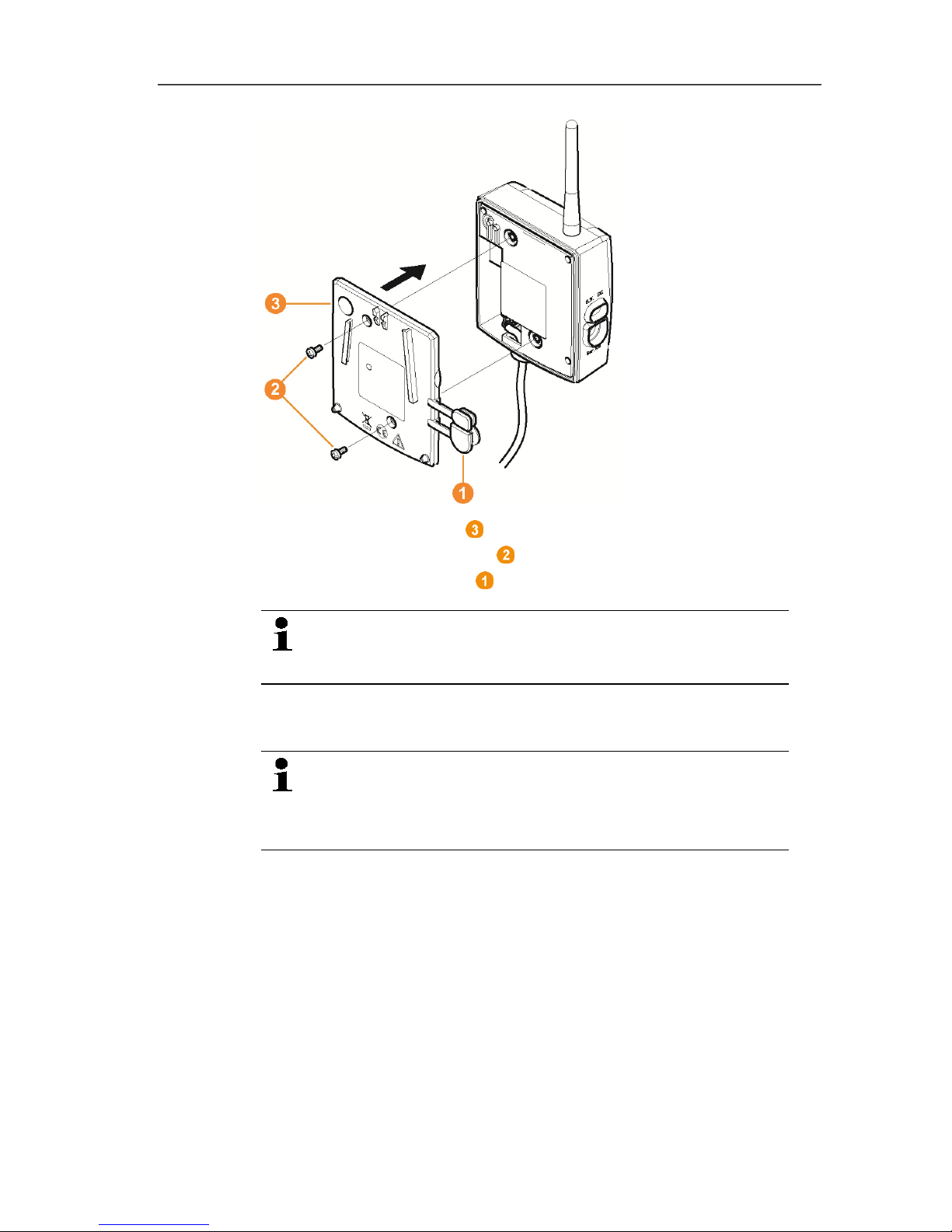
5.11.1.1. Connecting router with power supply (mains unit)
1. Open cover .
2. Insert mains cable .
3. Insert mains plug into a socket.
The wall mounting of a router is performed in the same
ways as for a probe; see "Mounting the probe on the
wall".
Page 46

5 First steps
46
Pos: 65 /TD/Erste Schritte/testo Saver is/Hardware erwei tern/01 a Router einbinden/ 01b Router-ACDC @ 1\mod_11979 78273593_79.doc x @ 6543 @ 4 @ 1
5.11.1.2. Connecting router with power supply (AC/DC)
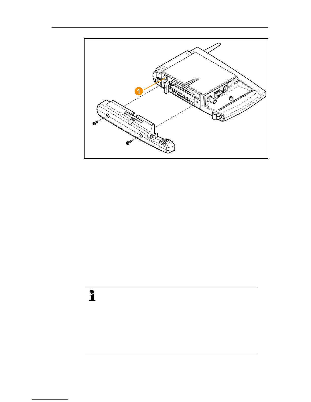
1 Remove protection caps .
2. Loosen screws on the rear of the router.
3. Remove housing cover of router .
4. Unscrew and remove cover cap of cable opening .
Page 47

5 First steps
47
5. Loosen clamping screws .
6. Route cabling through the cable opening and insert in the
terminals .
It is not necessary to note the polarity.
7. Tighten clamping screws.
Page 48
5 First steps
48
8. Place housing cover on the router.
9. Screw on housing cover .
10. Insert protection caps .
The wall mounting of a router is performed in the same
ways as for a probe; see "Mounting the probe on the
wall".
Pos: 66 /TD/Erste Schritte/testo Saveri s/Hardware erwei tern/01 a Router einbinden/ 02 Router anmelden @ 1\mod _1197548238578_79.d ocx @ 6274 @ 4 @ 1
5.11.1.3. Connecting router
You can connect a maximum of 30 routers to the
Saveris base.
The Saveris base can communicate directly with a
maximum of 15 routers.
Page 49

5 First steps
49
1. Change to the Info System menu at the Saveris base with the
[▼] button.
2. Press [Enter] to call up the Login function.
- The status bar in the display shows that the Saveris base is
ready for router detection.
Page 50
5 First steps
50
3. Hold down the connect key on the rear of the router until the
LED at the router begins to flash orange.
- The LED at the router briefly turns green if this was detected
by the Saveris base.
The LED at the Saveris base briefly flashes green and a
prompt appears in the display of the base for the connection of
more probes or routers.
Multiple routers cannot be connected at the Saveris
base simultaneously. Multiple routers can only be
connected one after the other.
4. At the Saveris base, press the
• [Esc] key if no more components are to be connected.
- A note on the required performance of the startup assistant
is shown on the display for about ten seconds. Then the
Saveris base changes to the Info System menu in which
the number of connected components is now shown.
• Press [Enter] if further components are to be connected;
see previous step.
Pos: 67 /TD/Erste Schritte/testo Saveri s/Hardware erwei tern/01 a Router einbinden/ 03 Fühler zuweisen @ 1\mod_1 197548250906_79. docx @ 6284 @ 4 @ 1
Page 51

5 First steps
51
5.11.1.4. Assigning probes
To assign a probe to a router, both must be connected
in the Saveris base.
1. Under Start | All Programs | Testo click on Saveris Startup
Wizard.
- The welcome dialogue of the startup assistant is shown.
2. Click on [Continue >].
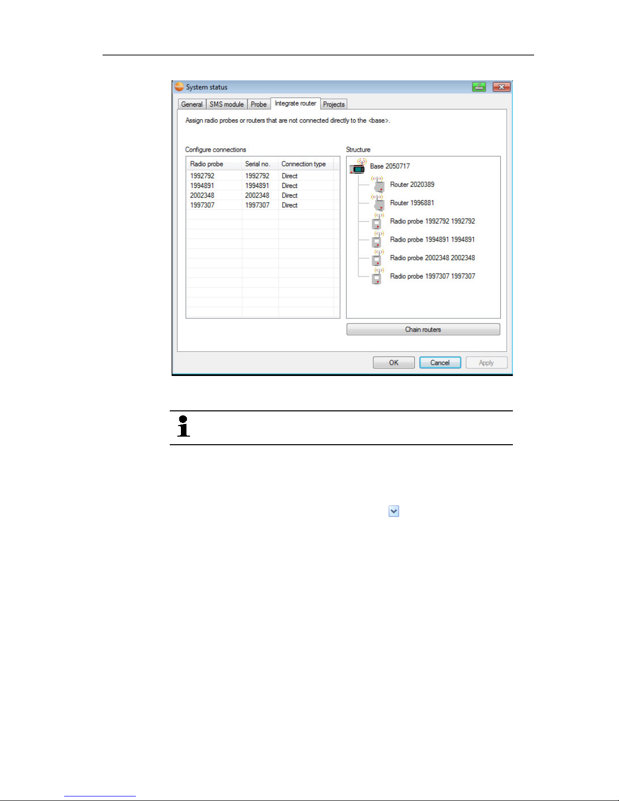
- The System status dialogue with the General tab is shown.
Page 52
5 First steps
52
3. Change to Router tab.
The Direct connection type means that the probe is
connected directly in the Saveris base or a converter.
4. Click in the Connection type cell of the probe which is to be
assigned to a router.
- The cell is shown as a selection list.
5. Open the selection list via the button and select the router to
which the probe is to be assigned.
> Perform steps 4 to 5 for all remaining probes whose
measurement data is to be transmitted to the Saveris base via a
router.
6. Position the probes and router at their mounting locations to
check the radio links.
7. Briefly press the connect key on the rear of the probe.
If the LED on the front of the probe flashes
• green, a radio link to the router exists.
• red, no radio link to the router exists.
Page 53

5 First steps
53
8. Briefly press the connect key on the rear of the router.
If the LED on the front of the router flashes
• green, a radio link to the Saveris base exists.
• red, no radio link to the Saveris base exists.
If no radio link exists after changing the location of the
probe and/or router, introduce a converter; see
"Integrating Saveris converter (optional)".
If you want to use probes in a router cascade, see
Starting up Ethernet probes, page 65
see Connecting routers in series, page 53
Pos: 68 /TD/Erste Schritte/testo Saveri s/Hardware erwei tern/01 a Router einbinden/ 04 Router hinteinander schalten @ 8\mod_1295 275223441_79.doc x @ 75773 @ 3 @ 1
5.11.1.5. Connecting routers in series
Max. three routers can be cascaded in series.
The measurement data of up to five radio probes can
be transmitted per router cascade to the Saveris base.
The wireless probes can be connected to any router in
the cascade.
A converter can be connected upstream of the router
cascade.
✓ All routers are connected to the power supply and registered on
the Saveris base.
1. Under Start | All Programs | Testo, click on Testo Saveris
Startup Wizard.
- The welcome dialogue box for the startup wizard is displayed.
Page 54

5 First steps
54
2. Click on [Next >].
- The System status dialogue box is displayed with the tab
General.
Page 55
5 First steps
55
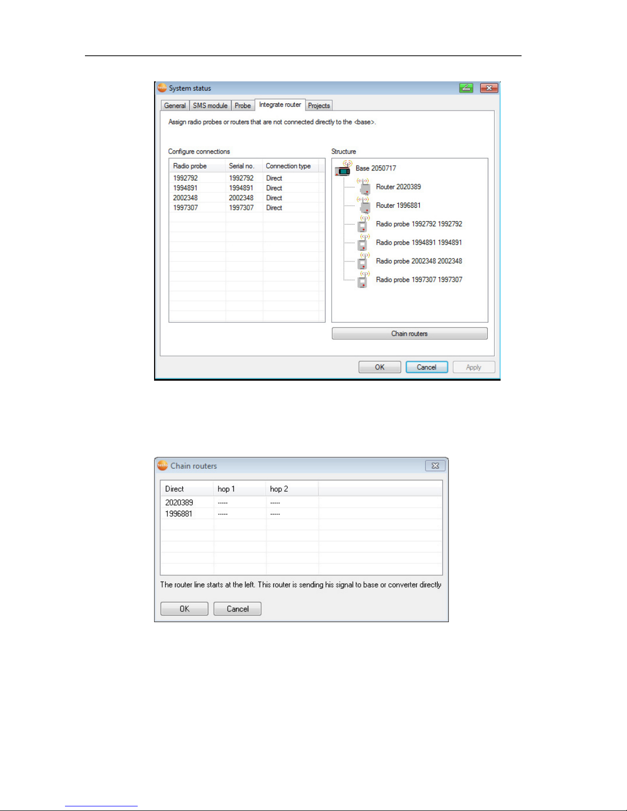
3. Switch to the Router tab.
4. Click on [Cascade routers].
- The Cascade routers window is opened.
5. Select routers in the order in which they should be connected in
series starting at the base (from left to right).
Page 56

5 First steps
56
6. Click on [Ok].
7. Check assignment in the structure diagram and click on [Next
>].
8. Place the routers in their installation locations to check the radio
connections.
9. Briefly press Connect on the back of the router that is next in
the series after the Saveris base (router 1 in the diagram).
If the LED on the front of the router flashes
• green, a radio link to the Saveris base exists.
• red, no radio link to the Saveris base exists.
10. Briefly press Connect on the back of the router that comes after
the first router in the series (router 2 in the diagram).
If the LED on the front of the router flashes
• green, a radio link to the router connected upstream of it in
the series exists.
• red, no radio link to the router connected upstream of it in
the series exists.
11. Briefly press Connect on the back of the router that comes after
the second router in the series and is therefore the furthest from
the base (router 3 in the diagram).
If the LED on the front of the router flashes
• green, a radio link to the router connected upstream of it in
the series exists.
• red, no radio link to the router connected upstream of it in
the series exists.
If no radio link exists after changing the location of the
router, introduce a converter; see "Integrating Saveris
converter (optional)".
If you want to integrate probes into the router cascade,
see Assigning probes, see Assigning probes, page 51.
Page 57

5 First steps
57
Pos: 69 /TD/Erste Schritte/testo Saver is/Hardware erwei tern/01 b IP-Adresse der Base zu weisen @ 12\mod_13383768 77611_79.docx @ 125816 @ 3 @ 1
5.11.2. Assigning an IP address to the Saveris base
(optional)
If an Ethernet probe, converter and/or extender is integrated into
the Saveris system, a static IP address should first be assigned for
the Saveris base.
For assignment of an IP address, the software must be installed ()
and the programming adapter 0440 6723 must be used.
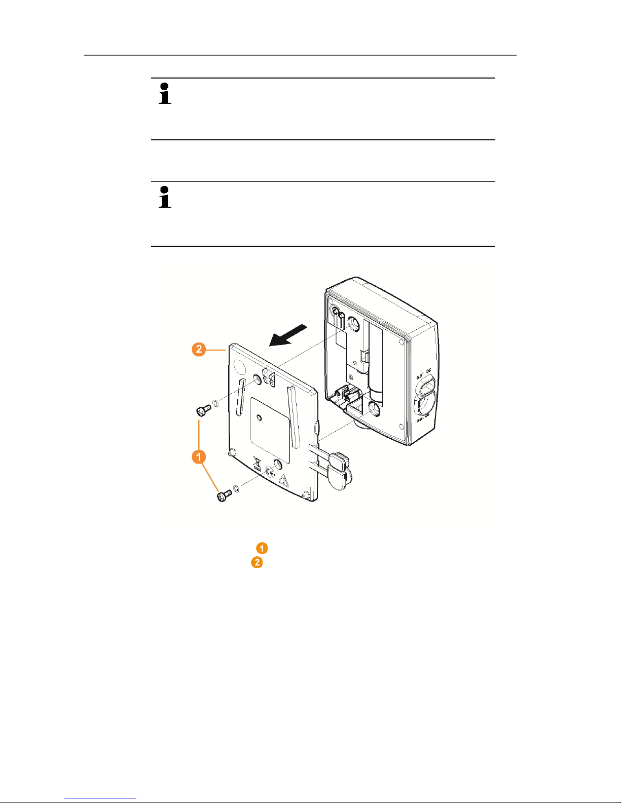
1. Undo the screw connection 1 and remove the base plate 2 from
the Saveris base.
2. Plug the USB cable into the Testo programming adapter (0440
6723) and connect to the service interface for the base.
Page 58
5 First steps
58
3. Connect the USB cable to the computer.
4. Via Start | All Programs | Testo | Testo Saveris Ethernet
Wizard, open the wizard for entering the connection settings.
5. Follow the wizard's instructions and assign the IP address for
the Saveris base.
see Installing Saveris software, page 39
Pos: 70 /TD/Erste Schritte/testo Saveri s/Hardware erweiter n/03 Ethernet-Fühler ei nbinden/00 Etherne t-Fühler einsetzen @ 1\m od_1197552336953_79. docx @ 6336 @ 4 @ 1
5.11.3. Integrating Saveris Ethernet probe (optional)
In addition to the Saveris radio probes, you can use probes that are
connected to the Ethernet interface of the Saveris base. This also
enables the data transfer from the probe to the base over long
stretches if you do not wish to use a router or converter.
All Ethernet components (Ethernet probe, converter, extender,
base where applicable) must be assigned IP addresses through the
programming adapter (0440 6723) via the Ethernet wizard.
If your computer has the Dynamic Host Configuration
Protocol (DHCP), the Ethernet components
automatically retrieve the IP address. Because the
DHCP address changes as standard following a certain
period of time, the base should be assigned a fixed IP
address. The IP address of the base must be manually
assigned to the probes, extenders and converters
through the adapter.
This chapter contains all required information for this.
Page 59
5 First steps
59
You can connect several Ethernet probes to the Saveris
base using a so-called switch. In this context, note that
a maximum of 150 probes can be connected or 450
measurement channels recorded at the Saveris base.
Pos: 71 /TD/Erste Schritte/testo Saveri s/Hardware erweiter n/03 Ethernet-Fühler ei nbinden/01 Netzwerkk abel @ 1\mod_1203421433 000_79.docx @ 8193 @ 4 @ 1
5.11.3.1. Connecting the network cable.
Only use high-quality network cables with a diameter
between 5.8 mm and 6.8 mm to ensure the
leaktightness of the probe housing.
Only use cables with an intact clip end.
1. Loosen screws on the rear of the probe and remove the
housing cover .
Page 60

5 First steps
60
2. Loosen screws at the panel for the network cable and
remove panel.
3. Slide network cable with the tongue pointing up into the
Ethernet jack until it engages.
If you wish to connect the Saveris Ethernet probe to the
power supply via the 24 V AC/DC plug-in/screw terminal
and not via the mains adapter, do not screw on the
housing cover until after connecting the power supply.
The connection for the power supply via plug-in/screw
terminal is performed as with the Saveris router; see
Connecting router with power supply (AC/DC), page 46.
4. Place the housing cover on the probe and screw it down.
You can connect the probe to the network via a network
hub or directly at the Saveris base via the Ethernet jack.
Pos: 72 /TD/Erste Schritte/testo Saveri s/Hardware erwei tern/03 Ethernet-Fühler ei nbinden/01c Stromver sorgung @ 1\mod_1203423 817781_79.docx @ 8270 @ 4 @ 1
5.11.3.2. Connecting Ethernet probe with power supply (mains unit)
The connection for the power supply via 24 V AC/DC
plug-in/screw terminal is performed as with the Saveris
router; see Connecting router with power supply
(AC/DC), page 46.
Page 61

5 First steps
61
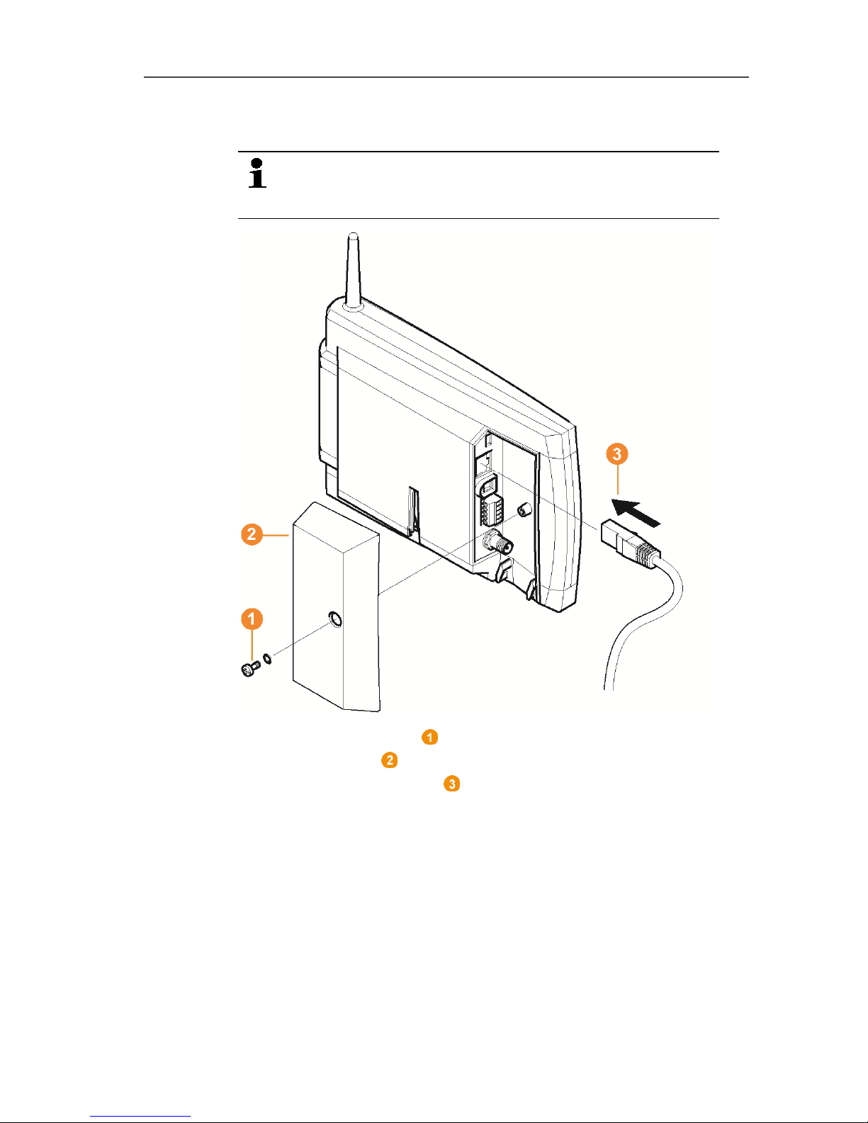
1. Open the cover for the power supply.
2. Insert mains cable .
3. Insert mains plug into a socket.
Pos: 73 /TD/Erste Schritte/testo Saveri s/Hardware erweiter n/03 Ethernet-Fühler ei nbinden/01b USB-Kab el @ 1\mod_120342381720 3_79.docx @ 8259 @ 4 @ 1
5.11.3.3. Connecting USB cable and installing driver (optional)
1. Open the cover of the service interface at the Saveris
Ethernet probe.
2. Connect the USB cable to the testo adapter (0440 6723)
and insert into the service interface .
✓ With Saveris H4E Ethernet probes, the external humidity probe
must be connected.
3. Connect the USB cable to the computer.
- The wizard for the installation of the driver is started.
4. Follow the directions of the installation wizard.
Page 62
5 First steps
62
Pos: 74 /TD/Erste Schritte/testo Saver is/Hardware erwei tern/03 Ethernet-Fühler einbinden/03 Verbindu ngsdaten zuweisen @ 1\ mod_1203421515781_79. docx @ 8226 @ 4 @ 1
5.11.3.4. Assigning connection data
You must now enter the connection settings for the Ethernet
probes.
1. Open the wizard for entering the connection settings via Start |
All Programs | Testo | Testo Saveris Ethernet Wizard.
- The wizard is started with the welcome dialogue.
2. Click on [Continue >].
- The Instrument address allocation dialogue is shown.
3. Enter IP address, Netmask and Gateway.
Page 63
5 First steps
63
The first two blocks of the IP address must match those
from the Saveris base in this example. The last two
blocks can be selected freely, but must differ from the
Saveris base.
The IP address, the netmask and the gateway can be
read off at the Saveris base in the Info Base menu; see
Displays, page 15.
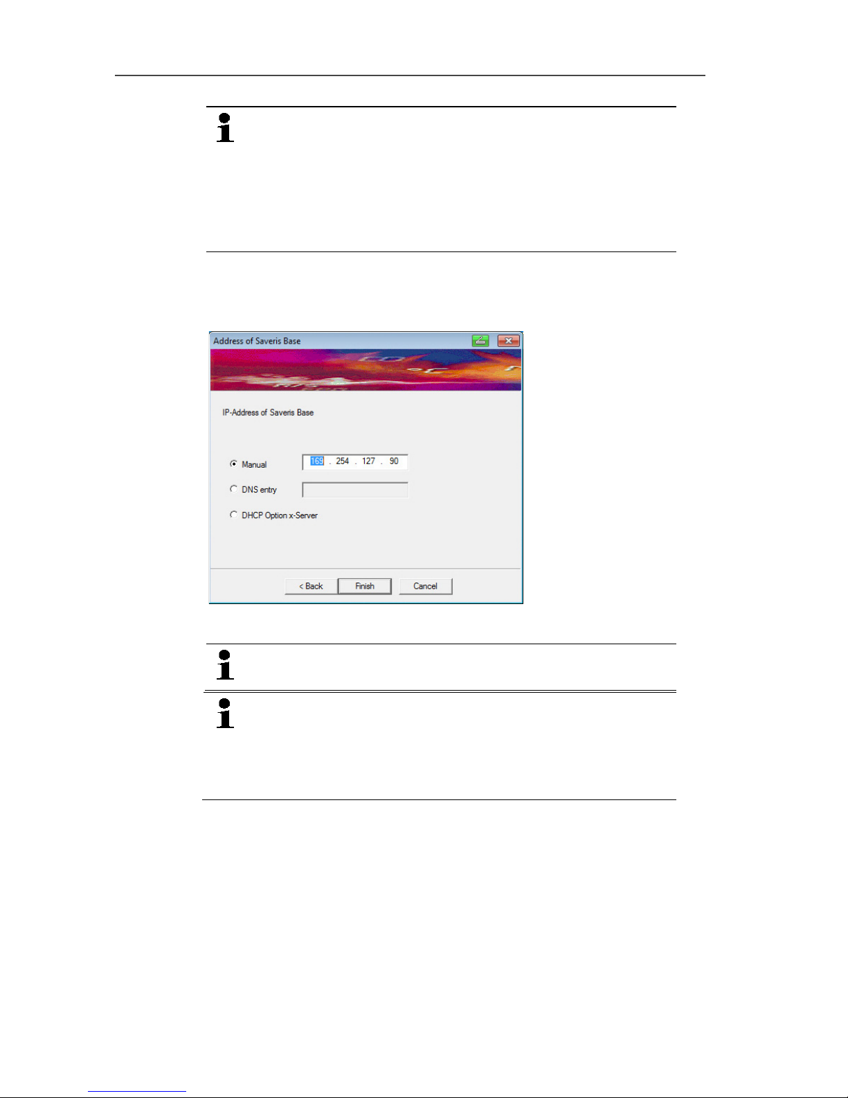
4. Click on [Continue >].
- The dialogue for the entry of the connection data for the base is
shown.
5. Enter IP address or DNS entry of the Saveris base.
The IP address can be read off at the Saveris base in
the Info Base menu; see Displays, page 15.
You can determine the DNS entry using the label on
the back of your Saveris base.
The DNS entry consists of the word "testo" and the last
six digits of the "MAC address" on the label excluding
spaces and hyphens (e.g. testo00081B).
6. Click on [Finish].
- The Ethernet probe is restarted, synchronized with the Saveris
base and the number of connected Ethernet probes in the
display of the base is increased by 1; see Displays, page 15.
Pos: 75 /TD/Erste Schritte/testo Saveri s/Hardware erwei tern/03 Ethernet-Fühler ei nbinden/04 Netzwerkk abel an Base anschließen @ 1\mod_1203430798656 _79.docx @ 8313 @ 4 @ 1
Page 64
5 First steps
64
5.11.3.5. Connecting the network cable to the Saveris base
You can integrate the Saveris base into a network via a
network hub or connect the Ethernet probe directly via a
network cable.
1. Loosen and remove screw connection.
2. Remove cover from Saveris Base.
3. Plug the network cable into the Saveris base.
Pos: 76 /TD/Erste Schritte/testo Saveri s/Hardware erweiter n/03 Ethernet-Fühler ei nbinden/05 Etherne t-Fühler inbetrieb neh men @ 1\mod_120342155198 4_79.docx @ 8237 @ 3 @ 1
Page 65

5 First steps
65
5.11.3.6. Starting up Ethernet probes
1. Via Start | All Programs | Testo | Startup Wizard, start the
wizard to start up new hardware components.
- The wizard opens with the welcome screen.
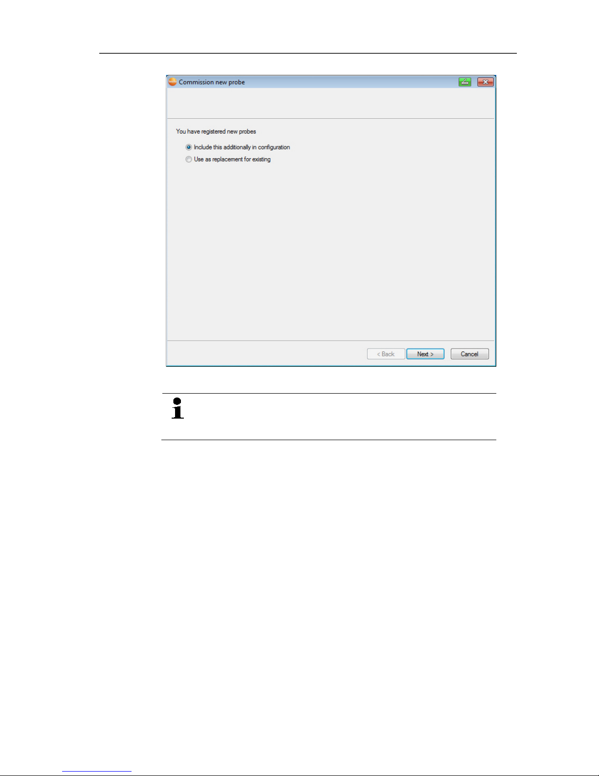
2. Click on [Next >].
- The Commission new probe dialogue box is displayed.
Page 66
5 First steps
66
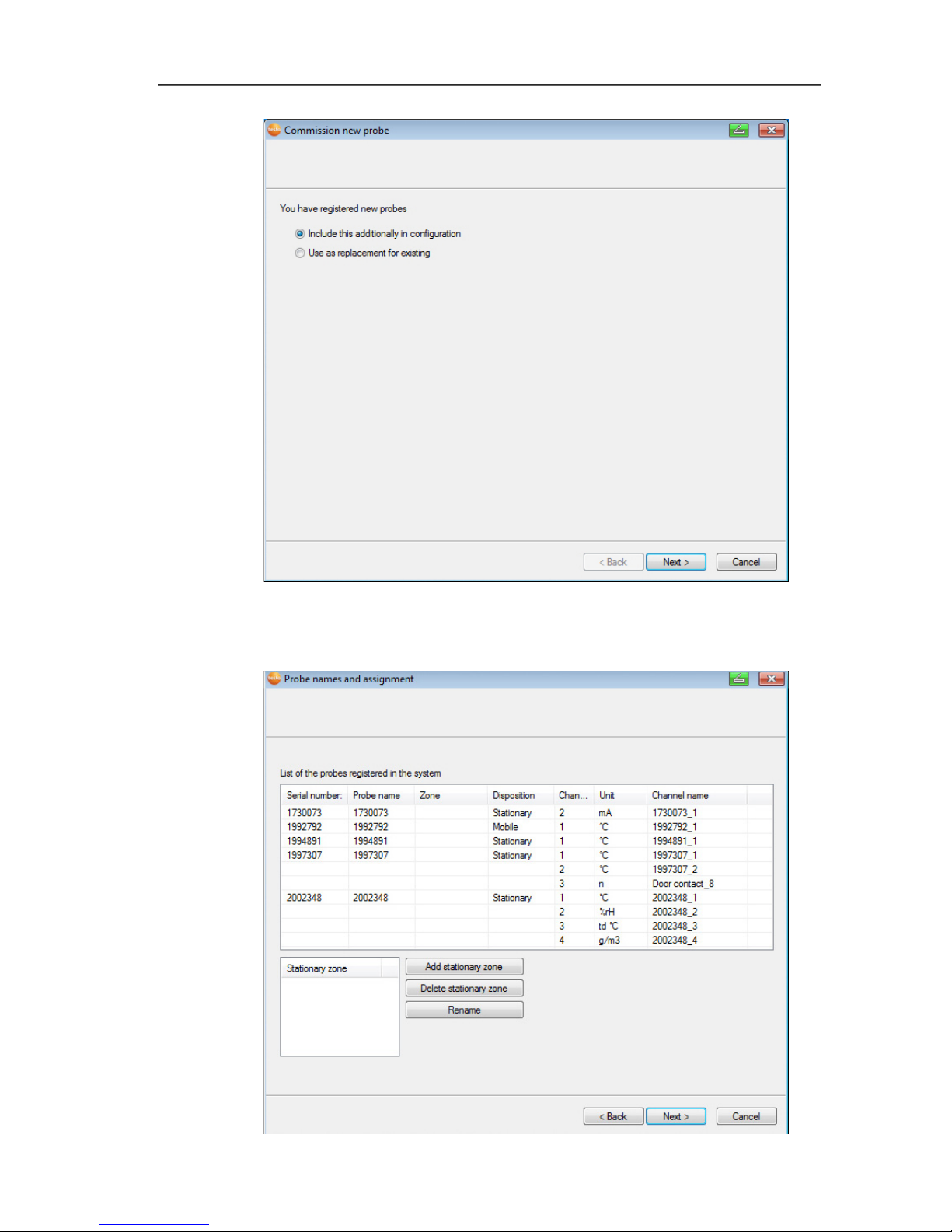
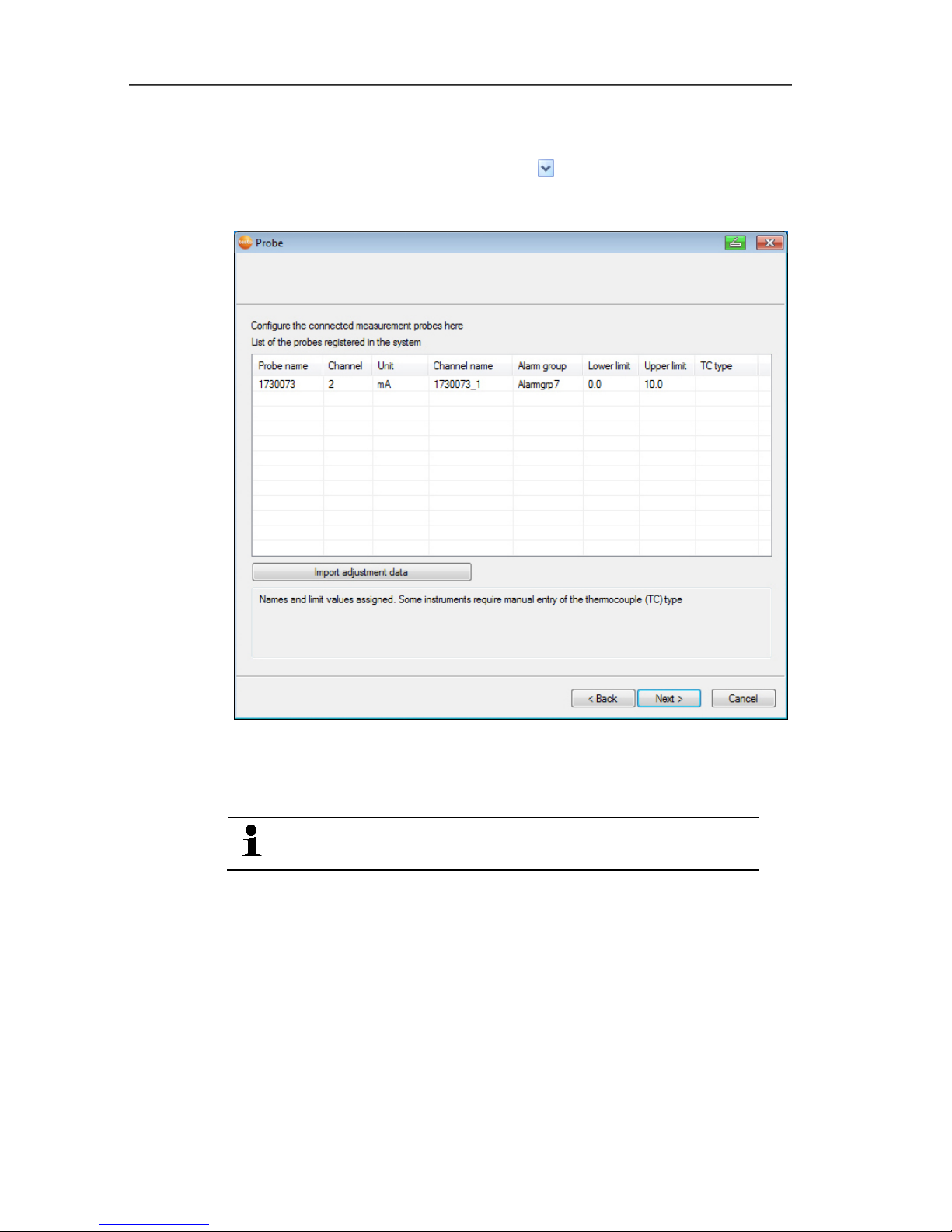
3. Leave default setting and click on [Next >].
- The list of probes newly registered in the Saveris base is
displayed.
Page 67
5 First steps
67
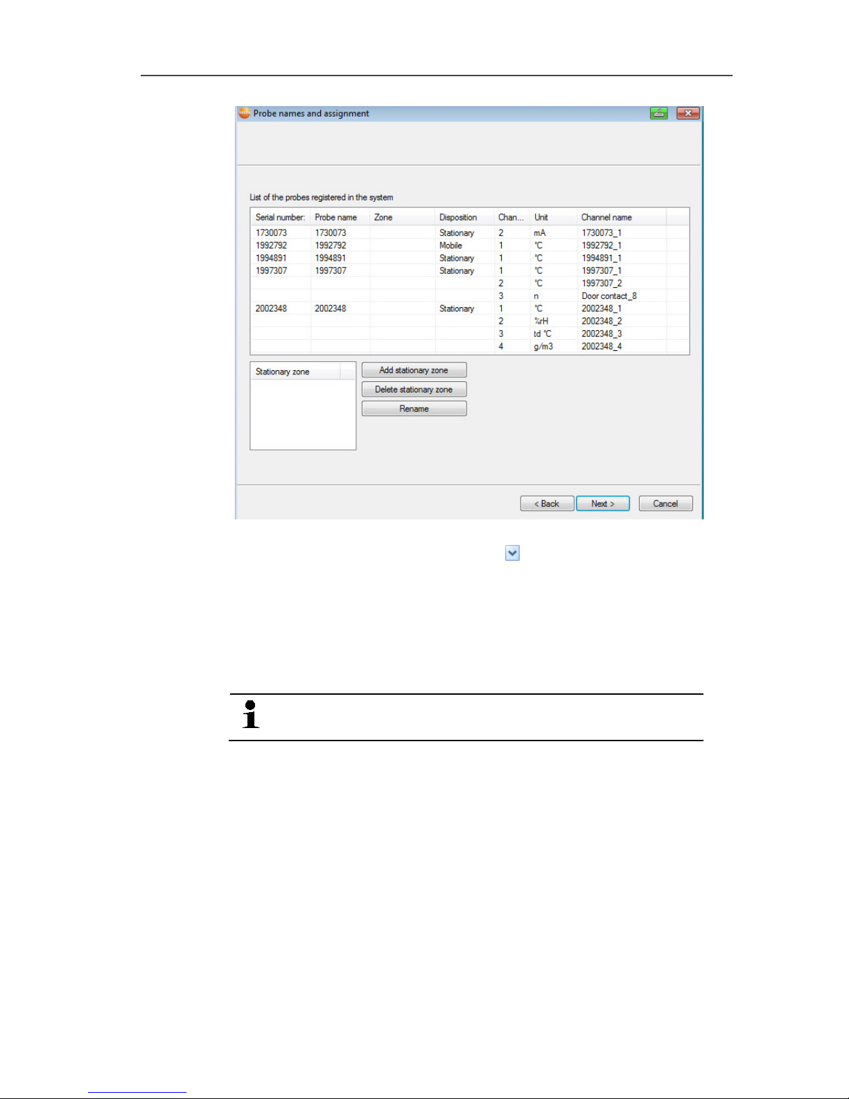
4. Click on [Add stationary zone].
5. Open the selection list via button and select the zone to
which the probe should be assigned.
6. Click on [Next >].
7. Click in the TE type field and enter the thermocouple element
type (K, J, T or S) if this information is necessary for the device.
8. If required, change the default values in fields Probe name and
Channel name.
Assign channel names that are not longer than
20 characters.
9. If required, import adjustment data for the individual probes:
Click on [Import adjustment data].
10. Click on [Next >].
- The settings for the measuring cycle are displayed.
Page 68

5 First steps
68
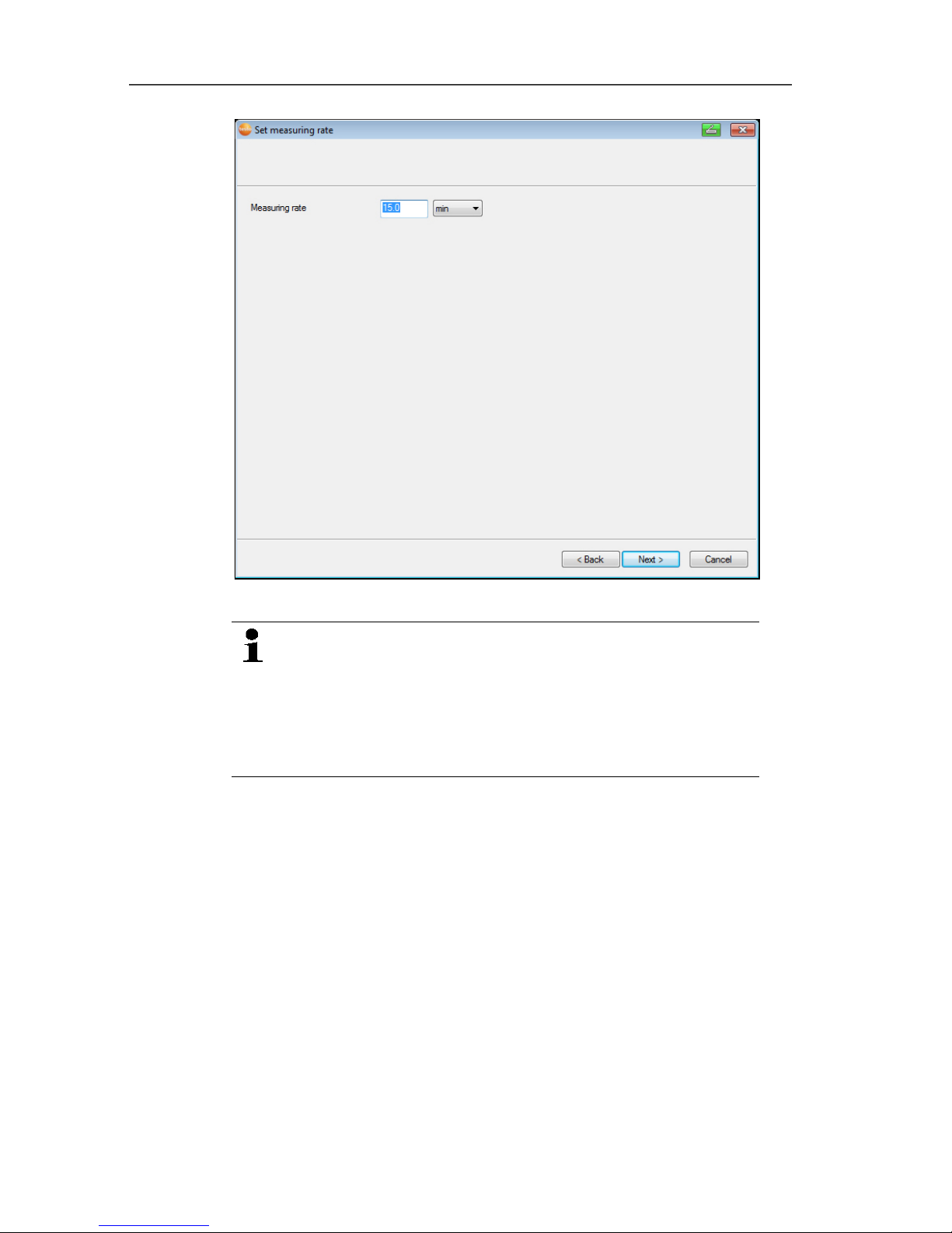
11. Enter Measuring cycle and define its Unit.
The measuring cycle determines the intervals at which
a new measured value is saved in the Saveris base.
Possible settings for the unit:
• sec (second)
• min (minute)
• h (hour).
12. Click on [Next >].
- The wizard is displayed with the start of measurement
configuration and the list of newly registered probes.
Page 69

5 First steps
69
13. Postpone the start of measurement if necessary.
14. Click on [Finish] to end the hardware startup.
- A message about the successful configuration of the hardware
is displayed.
15. Confirm the message by clicking [OK].
- The new hardware is now ready to be used.
Pos: 77 /TD/Erste Schritte/testo Saver is/Hardware erwei tern/02 Converter einbi nden/00 Converter ei nsetzen @ 1\mod_119755060 7093_79.docx @ 6315 @ 35 @ 1
5.11.4. Integrating Saveris converter (optional)
If the distance between the radio probe or router is too large for a
radio transmission, you can integrate a Saveris converter into the
measuring system. The converter is connected to the Saveris base
by means of an Ethernet cable and converts the radio signals to
Ethernet signals.
The measurement data of up to 15 radio probes/routers
can be transmitted with the converter to the Saveris
base.
You can connect several converters to the Saveris base
using a so-called switch. In this context, note that a
maximum of 150 probes can be connected or 450
measurement channels recorded at the Saveris base.
Page 70

5 First steps
70
The preparation for the commissioning of a converter is
performed as with a Saveris Ethernet probe; see
Connecting the network cable., page 59 up to and
including see Starting up Ethernet probes, page 65
Connecting probe or router to converter
1. Briefly press the connect button on the rear of the converter.
- The LED at the converter lights green and the converter is
ready for probe detection.
2. Press the connect key on the rear of the probe/router until the
LED at the probe/router begins to flash orange.
- The LED at the probe/router briefly turns green if this was
detected by the Saveris converter.
The probe/router is connected at the converter and this
transmits the measurement data to the Saveris base.
Pos: 78 /TD/Erste Schritte/testo Saver is/Hardware erwei tern/04 Analogkoppler ei nbinden/00 Analogko ppler einsetzen @ 4\mod_1 248880773887_79.doc x @ 46514 @ 2555 @ 1
5.11.5. Integrating Saveris analog coupler (optional)
Using a Saveris analog coupler, you can integrate a transmitter
with standardized current/voltage interfaces into the Saveris
measuring system and monitor it. The Saveris analog coupler
thereby enables the integration of additional parameters other than
temperature and humidity into the Saveris measuring system.
The integration of an analog coupler is performed in three steps:
1. Connect transmitter to analog coupler.
2. Connect analog coupler to the Saveris base.
3. Parameterize analog coupler.
Connecting transmitter to analog coupler
You can supply the transmitter with power via the analog coupler or
select a separate power supply.
The circuit diagrams can be found in the analog coupler startup
instructions which are delivered together with the analog coupler.
Connecting analog coupler to the Saveris base.
The analog coupler U1 is connected to the Saveris base like a
Saveris radio probe (see Connecting radio probe page 37)
The analog coupler U1E is started up and connected to the Saveris
base like a Saveris Ethernet probe (see Integrating Saveris
Ethernet probe (optional) page 58)
Page 71

5 First steps
71
Parameterizing analog coupler with Startup Wizard
1. Under Start | All Programs | Testo click on Testo Saveris
Startup Wizard.
- The welcome dialogue of the startup wizard is shown.
2. Click on [Next >].
- The Commission new probe dialogue is shown.
Page 72
5 First steps
72
3. Leave default setting and click on [Next >].
Analog couplers can always only be additionally
included in the configuration and cannot be used as a
replacement for ones that are already present.
- The Scale dialogue is displayed.
Page 73

5 First steps
73
The fields of the Scale, Display from, to, Unit and
Decimal places columns are preassigned. These fields
can be changed individually.
4. Select Scale (see type plate/transmitter operating instructions).
5. Enter Display from and to (see type plate/transmitter operating
instructions).
6. Select Unit. If the desired unit is not available in the selection
list: Add via [User-defined unit].
7. Select number of Decimal places.
8. Click on [Set up sum channel] if the summation of a particular
unit is required.
9. Click on [Next >].
- The list of the probes newly registered in the Saveris base is
shown.
Page 74
5 First steps
74
10. Click on [New stationary zone].
11. Open the selection list via button and select the zone to
which the probe should be assigned.
12. Click on [Next >].
13. Click in the TE type field and enter the thermocouple element
type (K, J, T or S) if this information is necessary for the device.
14. If required, change the default values in fields Probe name and
Channel name.
Assign channel names that are not longer than
20 characters.
15. If required, import adjustment data for the individual probes:
Click on [Import adjustment data].
16. Click on [Next >].
- The settings for the measuring cycle are displayed.
Page 75
5 First steps
75
17. Enter Measuring cycle and define its Unit.
The measuring cycle determines the intervals at which
a new measured value is saved in the Saveris base.
Possible settings for the unit:
• sec (second)
• min (minute)
• h (hour).
18. Click on [Next >].
- If a router is registered on the Saveris base, the configuration of
the connection type for the probes is shown.
If you have not registered a router, continue with step 24.
Page 76

5 First steps
76
19. Click in the Connection type cell of the probe to be assigned to
a router.
- The cell is shown as a selection list.
20. Use button to open the selection list and select the router to
which the probe should be assigned.
Probes in a mobile zone cannot be assigned to a router.
21. Perform steps 21 and 22 for any other probes with
measurement data to be transmitted to the Saveris base via a
router.
22. Click on [Next >].
- The wizard is displayed with the start of measurement
configuration and the list of newly registered probes.
Page 77
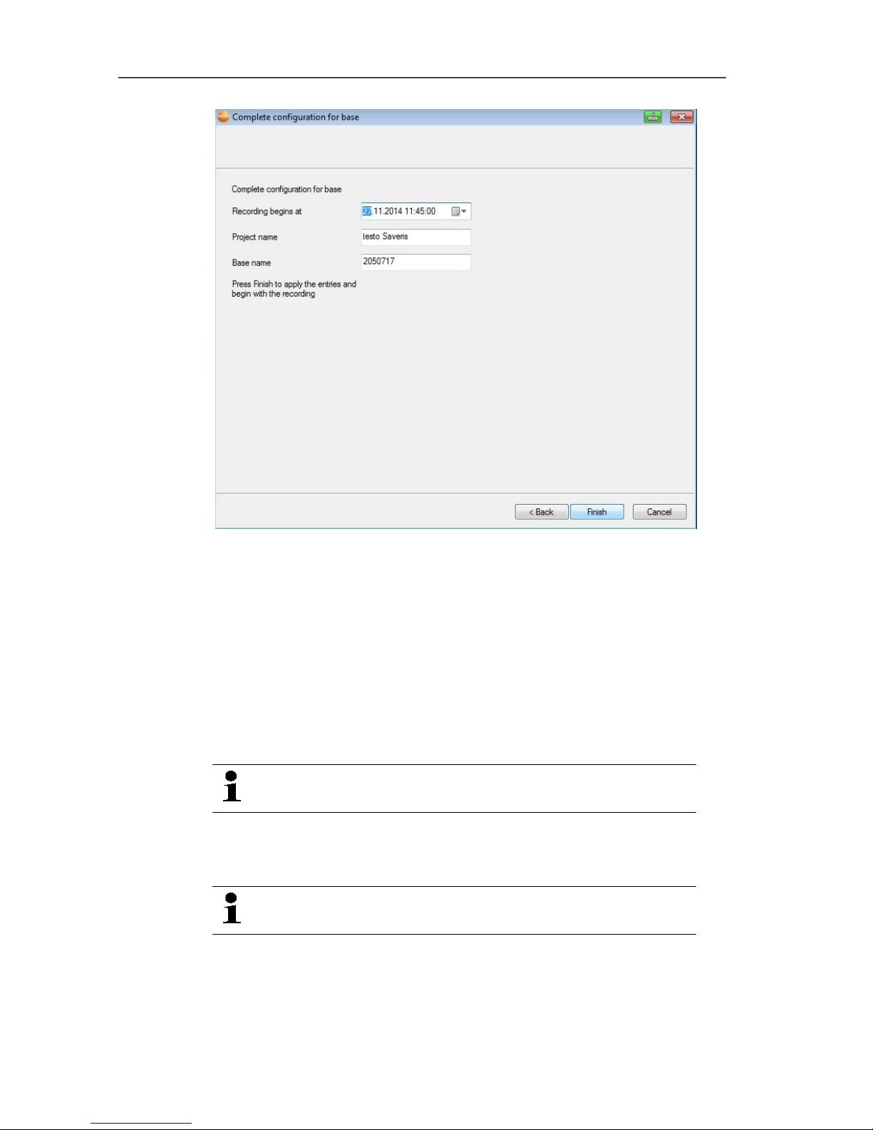
5 First steps
77
23. Postpone the start of measurement if necessary.
24. Click on [Finish] to end the hardware startup.
- A message about the successful configuration of the hardware
is displayed.
25. Confirm the message by clicking [OK].
- The new hardware is now ready to be used.
Pos: 79 /TD/Erste Schritte/testo Saveri s/06 ****Probelauf /00 Probelauf und Abnah me durchführen @ 0\mod_118 9157354187_79.doc x @ 4054 @ 3 @ 1
5.12. Performing the test run
The test run must be performed to ensure proper
operation of the measuring system.
Pos: 80 /TD/Erste Schritte/testo Saver is/06 ****Probelauf /01 Systemverfügbar keit prüfen @ 0\mod_11891 57395875_79.doc x @ 4094 @ 3 @ 1
5.12.1. Checking system availability
Wait for the first connection between the Saveris base
and the probes to check the system availability.
> Click on System in the navigation area.
- The following entries are shown in the tree structure in the data
window:
• Base
Page 78

5 First steps
78
• Radio probe
• Ethernet probe
• Router
• Converter.
1. Open the Radio probe entry.
- The active channels of the probes connected in the system are
shown.
2 Click on a channel to open the settings and check the Radio
quality.
> Repeat step 2 for all other probes.
If no values have accumulated for a probe for a while,
check whether a connection exists between the probe
and the Saveris base by briefly pressing the connect
button at the probe. The LED at the probe shows the
connection status; also see "Meaning of the LED
displays at the probes " for this.
Pos: 81 /TD/Erste Schritte/testo Saveri s/06 ****Probelauf /Systemtest durc hführen @ 10\mod_13213615530 28_79.docx @ 103136 @ 3 @ 1
5.12.2. Testing the system
For a simple system test:
• In the System main menu:
◦ All probes are visible, synchronisation of the probes is
complete (none have an asterisk * after their name)
◦ All components have the current firmware version
◦ Under operating data: the last probe data transfer was
recently
◦ The communication statistics of the individual probes are
good
• In the data view of the zones:
◦ No noticeable alarms occurred during maintenance
◦ In the diagram (selecting individual measuring points), the
measuring point selections are regularly incorporated in the
measuring cycle - without gaps.
• Generate and acknowledge at least one SMS or email alarm
• Wait for an automatic report or create it for test purposes under
Options | System test
• No open alarms in the overview window
Pos: 82 /TD/Erste Schritte/testo Saver is/06 ****Probelauf /Systemtest Hinwei s Base-Backup @ 10\mod_132 1606974422_79.doc x @ 103203 @ @ 1
After a successful system test, a base backup is
recommended, see Saving data in the Saveris base, page
142.
Page 79
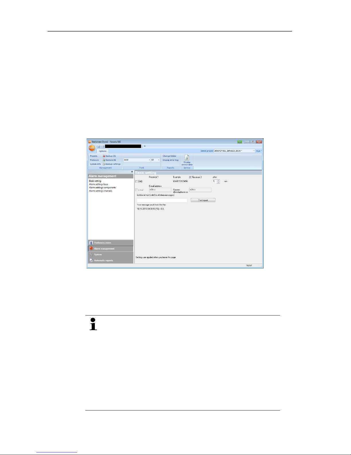
5 First steps
79
Pos: 83 /TD/Erste Schritte/testo Saveri s/06 ****Probelauf /02 Alarmkette prüfen @ 0\ mod_1189157374281_79. docx @ 4064 @ 2 @ 1
5.12.3. Checking alarm chain
You can trigger an alarm and control the sending of the messages
without having to bring about a real alarm situation.
> In the navigation area, click on Alarm management.
- In the data window, the Basic setting and Alarm overview
submenus as well as the probes connected in the Saveris base
are shown.
1. Click on Basic setting.
- The basic setting for the alarms is shown in the display range.
2. Click on the [SMS test report] button.
- A test report is sent to the mobile phone number entered.
Pos: 84 /TD/Erste Schritte/testo Saveri s/07 **** Montage der Hard ware/00 Hardware montier en @ 0\mod_118915757 9984_79.docx @ 4124 @ 3 @ 1
5.13. Mounting the hardware
The notes in chapter "Ensure safety" must absolutely be
observed when mounting the Saveris components.
Do not mount the Saveris base and the probes at their
locations until the measuring system functions as
expected.
At sub-zero temperatures, the Li-ion rechargeable
batteries in the base and in the Ethernet probes are not
charged. Avoid assembly sites for these components
with long-lasting, prevalent sub-zero temperatures.
After mounting, perform another test run of the system;
also see "Performing the test run".
Page 80

5 First steps
80
Pos: 85 /TD/Erste Schritte/testo Saveri s/07 **** Montage der Hard ware/01 Base an der Wand monti eren @ 0\mod_1189157492 531_79.docx @ 4105 @ 3 @ 1
5.13.1. Mounting the Saveris base on the wall
When selecting the location for the Saveris base,
please take into account that this must be positioned
close enough to the computer used and a possible
power supply in accordance with the cabling provided.
The mounting materials (screws, anchor plugs etc.) are
not included in the delivery.
1. Position wall bracket at the desired location.
2. Using a pen, mark the locations for the fastening screws.
The distance between the fastening screws is 25 mm.
3. Prepare the fastening location for the attachment in accordance
with the material (e.g. drill hole, insert anchor plug).
4. Fasten wall bracket using appropriate screws.
Page 81
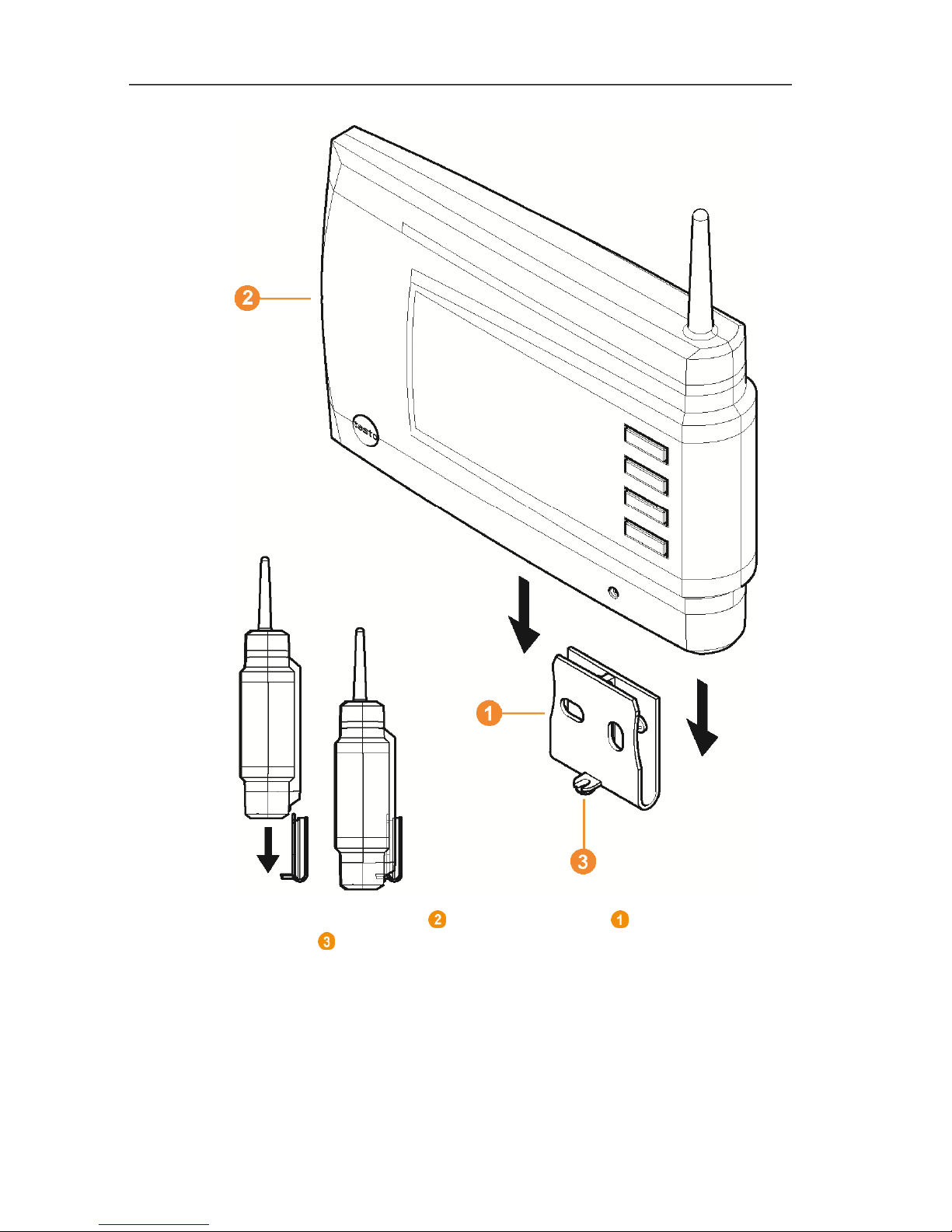
5 First steps
81
5. Place Saveris base on the wall bracket and secure with
screw .
Pos: 86 /TD/Erste Schritte/testo Saveri s/07 **** Montage der Hard ware/01b Base mit Standfuß @ 0\ mod_1190975629546_79. docx @ 5233 @ 3 @ 1
Page 82

5 First steps
82
5.13.2. Setting up Saveris base with stand
When selecting the location for the Saveris base, take
into account the following points:
• The Saveris base must stand on a level, non-slip
surface.
• The Saveris base must be positioned close enough
to the computer used and a possible power supply
in accordance with the cabling provided.
1. Place the Saveris base on the stand .
2. Set up the Saveris base at the desired location.
Page 83

5 First steps
83
Pos: 87 /TD/Erste Schritte/testo Saveri s/07 **** Montage der Hard ware/03 Fühler montier en @ 0\mod_1189157541812 _79.docx @ 4114 @ 3 @ 1
5.13.3. Mounting the probe on the wall
When selecting the location, take into account the
following points:
• The range of the probe may not be exceeded; see
Connecting radio probe, page 37 and see
Performing the test run, page 77
• Attach the probe in such a way that the readings
cannot be distorted, e.g. by exposure to direct
sunlight
The mounting materials (screws, anchor plugs etc.) are
not included in the delivery.
1. Position wall bracket at the desired location.
2. Using a pen, mark the locations for the fastening screws.
The distance between the fastening screws is 30 mm.
3. Prepare the fastening location for the attachment in accordance
with the material (e.g. drill hole, insert anchor plug).
4. Fasten wall bracket using appropriate screws.
The wall bracket must be screwed down with the
smooth surface facing the wall.
Page 84

5 First steps
84
5. Place probe on the wall bracket until it engages.
Please refer to "Removing probe from wall bracket" for
removing the probe from the wall bracket.
Pos: 88 /TD/Erste Schritte/testo Saver is/07 **** Montage der Hard ware/04 System prüf en @ 0\mod_1191327191562_7 9.docx @ 5362 @ 3 @ 1
5.13.4. Checking the measuring system again
> Perform another test run at the measuring system; see
"Performing the test run".
After mounting the hardware, perform another check of
the system to test the proper function of the measuring
system.
You can thus recognize whether probes are located
outside of the range of the Saveris base, where
applicable, or the radio link is interfered with by
structural conditions.
Page 85

6 Using the product
85
Pos: 89 /TD/--- Seitenwechsel --- @ 0\mod_1173774430601_0.docx @ 283 @ @ 1
Pos: 90 /TD/Überschriften/6. Produkt verwenden @ 0\mod_11737749 28554_79.docx @ 328 @ 2 @ 1
6 Using the product
Pos: 91 /TD/Produkt verwenden/testo Sa veris/01 Start/02_Bedi enoberfläche_01 @ 0\ mod_1189076833359_79. docx @ 3943 @ 2 @ 1
6.1. User interface
In this chapter, you learn how the user interface of the Saveris
software is designed.
Pos: 92 /TD/Produkt verwenden/testo Sa veris/01 Start/02_Bedi enoberfläche_02 @ 1\ mod_1197983797765_79. docx @ 6593 @ @ 1
Pos: 93 /TD/Produkt verwenden/testo Saveri s/01 Start/02_Bedienober fläche_03 SBE @ 1\mod_11 97983802515_79.doc x @ 6603 @ @ 1
Menu bar
Menu Explanation
All functions that you require to open, close,
save, delete and print.
The recently used files are also available as a
list for opening.
Using this menu, the program can also be
ended.
With the Send command, you can send
measurement results by e-mail.
Saves the current selection in a file.
Prints the current view.
Setting options for the menu bar.
Start Functions for the clipboard, editing the
measurement data records, the evaluation, the
view and the font in the tables and diagrams.
Page 86

6 Using the product
86
Menu Explanation
Edit Functions for evaluating the diagrams or tables
and possible settings for the curves and axes in
the diagram view.
Options Setting options for the display of curves and the
display of service data.
Templates Selection of the report heads and editing
functions for the templates.
Select project
Selection of all projects already created.
Pos: 94 /TD/Produkt verwenden/testo Sa veris/01 Start/02_Bedi enoberfläche_04 @ 1\ mod_1197983805828_79. docx @ 6613 @ @ 1
Data range
The measurement data are managed in the data range. You
can create new groups of readings and copy the data from
individual channels within the groups.
Pos: 95 /TD/Produkt verwenden/testo Sa veris/01 Start/02_Bedi enoberfläche_05 @ 1\ mod_1197983809546_79. docx @ 6623 @ @ 1
Display range
In the display range, the readings are represented as diagrams
and tables and the alarms received are listed.
Pos: 96 /TD/Produkt verwenden/testo Sa veris/01 Start/02_Bedi enoberfläche_06 @ 1\ mod_1197983817359_79. docx @ 6643 @ @ 1
Calendar and acknowledging alarms
The Calendar tab is used for fast navigation within the data
records. Open the data records in the display range by clicking
on a certain day in the calendar or marking a period of several
days in the calendar with the mouse button pressed.
In the Acknowledgement tab, confirm the alarms received.
Pos: 97 /TD/Produkt verwenden/testo Sa veris/01 Start/02_Bedi enoberfläche_07 @ 1\ mod_1197983827015_79. docx @ 6653 @ @ 1
Navigation area
In the navigation area, change to
• the display of Data and
• the settings for the Alarms, the System and the Reports.
Pos: 98 /TD/Produkt verwenden/testo Sa veris/01 Start/02_Bedi enoberfläche_08 @ 1\ mod_1197984029171_79. docx @ 6663 @ @ 1
Status bar
Shows the status information for the software.
Pos: 99 /TD/Produkt verwenden/testo Sa veris/02 Menüs und Befehl e der Ribbon-Leiste/00 Menü s und Befehle @ 0\mod_11902 79903078_79.doc x @ 4975 @ 3 @ 1
Page 87

6 Using the product
87
6.2. Menus and commands
In this chapter, you learn which menus and commands are
available to you and what you can use these commands for.
Pos: 100 /TD/Produkt verwenden/testo Sa veris/02 Menüs und Befeh le der Ribbon-Leiste/01 S tart/00 Menü Start @ 0\mod_1 190280034765_79.doc x @ 4984 @ 5 @ 1
6.2.1. Start
Pos: 101 /TD/Produkt verwenden/testo Sa veris/02 Menüs und Befeh le der Ribbon-Leiste/01 S tart/01 Zwischenabl age @ 0\mod_1189605664203 _79.docx @ 4484 @ 5 @ 1
Start | Clipboard menu
Menu
function
Description
Copy
Copies the marked element onto the clipboard.
Pos: 102 /TD/Produkt verwenden/testo Sa veris/02 Menüs und Befeh le der Ribbon-Leiste/01 S tart/02 Bearbeiten @ 0\ mod_1189605697875_79. docx @ 4494 @ 5 @ 1
Menu Start | Edit zones
Menu function Description
Edit zone Changes the allocation of the channels to the
selected zone.
New zone
Creates a new measured value group.
Delete
Deletes the selected element.
Rename
Renames the selected zone.
Pos: 103 /TD/Produkt verwenden/testo Sa veris/02 Menüs und Befeh le der Ribbon-Leiste/01 S tart/05 Berichte er stellen @ 14\mod_137285 3119429_79.doc x @ 169873 @ 5 @ 1
Menu Start | Create reports
Menu function Description
One-off report Define report contents and create a one-off
report.
Pos: 104 /TD/Produkt verwenden/testo Sa veris/02 Menüs und Befeh le der Ribbon-Leiste/01 S tart/03 Auswertung @ 0\ mod_118960581256 2_79.docx @ 4524 @ 5 @ 1
Start | Evaluation menu
Menu
function
Description
Day Shows the calendar for the selection of the day
in order to call up the data from the
corresponding day or days from the database.
Month Shows the calendar for the selection of the
month in order to call up the data from the
corresponding month from the database.
Page 88

6 Using the product
88
Pos: 105 /TD/Produkt verwenden/testo Sa veris/02 Menüs und Befeh le der Ribbon-Leiste/01 S tart/04-1 Ansicht @ 0\ mod_1189605850812 _79.docx @ 4534 @ 3 @ 1
Start | View menu
Menu
function
Description
Diagram Changes to the presentation of the data in a
diagram.
Table Changes to the presentation of the data in a
table.
Alarms Opens or closes the alarm overview and
acknowledgement.
Pos: 106 /TD/Produkt verwenden/testo Sa veris/02 Menüs und Befeh le der Ribbon-Leiste/01 S tart/Suchen @ 5\mod_1 265818091694_79.do cx @ 57304 @ 5 @ 1
Start | Search menu
Menu
function
Description
Search
Opens a search window in the Data and
System navigation areas in which zones and
channels can be searched through via textual
word search.
Pos: 107 /TD/Produkt verwenden/testo Sa veris/02 Menüs und Befeh le der Ribbon-Leiste/02 Be arbeiten/00 Menü Bear beiten @ 0\mod_11902801067 96_79.docx @ 4993 @ 5 @ 1
6.2.2. Edit
Pos: 108 /TD/Produkt verwenden/testo Sa veris/02 Menüs und Befeh le der Ribbon-Leiste/02 Be arbeiten/02 Bearbei ten (Diagramm) @ 0\ mod_1189606502281_79.doc x @ 4555 @ 3 @ 1
Edit in the diagram view
The Edit (diagram) menu is only shown if the diagram is activated
by clicking in the window.
Edit | Tools (diagram) menu
Menu
function
Description
Zoom in Drag to form a rectangle in the diagram window
to zoom in on the highlighted area.
Click on [Original size] to display the diagram
in its total size again.
Crosshairs Crosshairs with which the curve can be
followed are shown by clicking on a point of the
measurement curve. The date, time, reading
number and reading are shown in the process.
Page 89

6 Using the product
89
Menu
function
Description
Regression
curve
Regression curves are an aid for being better
able to assess large, unclear amounts of data.
In this process, "outliers" are suppressed and
the actual course of the curve is reproduced
using a theoretical, mathematical function.
The regression curve is shown by clicking on a
measurement curve. The regression
coefficients are shown in the status bar.
Edit | Curves (diagram) menu
Menu
function
Description
C:1, C:n Legend for the diagram. Click on the entry of a
curve and the dialogue for the characteristics of
the curve is opened.
Edit | Value axis (diagram) menu
Menu
function
Description
Upper limit
range of
values
Maximum of the shown range of values.
Lower limit
range of
values
Minimum of the shown range of values.
Grid
Scaling of the value axis.
Edit | Time axis (diagram) menu
Menu
function
Description
Grid
Scaling of the time axis.
Pos: 109 /TD/Produkt verwenden/testo Saveri s/02 Menüs und Befehle der Ribb on-Leiste/02 Bearbei ten/03 Bearbeiten (Tabe lle)_SBE @ 0\mod_11896065 37468_79.docx @ 4565 @ 35 @ 1
Page 90

6 Using the product
90
Edit in the table view
The Edit (table) menu is only shown if the table is activated by
clicking in the window.
Edit | Tools (table) menu
Menu
function
Description
Mark Mark data over a definable time period or
definable lines (index range).
Drop marking
Drops the marking.
Extra lines
(minimum,
maximum,
mean value)
Inserts a row with the corresponding value for
the overall table at the end of the table.
The min, max and average values
cannot be calculated via a period/index
range defined in the table.
Compress
Compresses the table to definable intervals.
Only the first and the last value are shown for
the individual intervals. The other readings are
hidden.
Drop
compression
Drops the compression.
Edit | Find (table) menu
Menu
function
Description
Minimum Shows the smallest reading of the selected
channel within the table.
Maximum Shows the largest reading of the selected
channel within the table.
Pos: 110 /TD/Produkt verwenden/testo Sa veris/02 Menüs und Befeh le der Ribbon-Leiste/03 E xtras/00 Menü Extras @ 0\ mod_1190280173640_ 79.docx @ 5003 @ 3 @ 1
6.2.3. Options
Pos: 111 /TD/Produkt verwenden/testo Sa veris/02 Menüs und Befeh le der Ribbon-Leiste/03 E xtras/01 Verwaltung @ 1\ mod_11973738084 53_79.docx @ 6173 @ @ 1
Menu Options | Administration
Menu
function
Description
Projects
Opens the dialogue box for selecting a project.
Measurement
records
Opens a log file that you can send to Customer
Service in the event of a problem.
Page 91
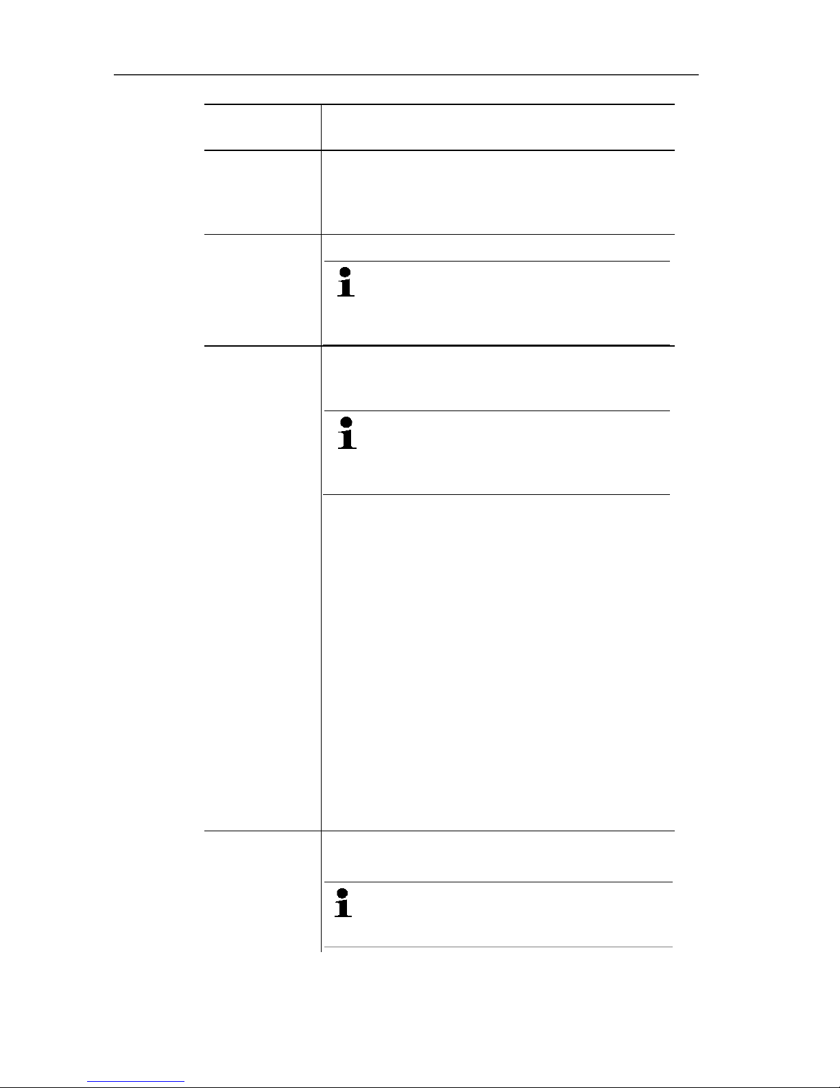
6 Using the product
91
Menu
function
Description
System test With this function, you can test individual
functions of the Saveris system. Please contact
Testo Customer Service. Contact details can be
found under www.testo.com/service-contact
Database
backup
Creates a backup file for all projects.
Administrator rights are required and
the directory to which the backup file is
to be saved must be activated for the
network service.
Restore
database
Loads the previously saved backup file and
thereby enables access to the saved project
data.
Administrator rights and re-installation
of the system are required. The startup
wizard must not be started before
restoring the database.
1. Open Saveris Client.
2. Select Project on the dialogue box and click
on [Cancel].
3. Click on Options | Administration |
Restore database.
4. Select the *bak file containing the database
backup.
5. In the Find folder dialogue box, select the
directory for the backup (e.g.
c:\Programs\Microsoft SQL
Server\MSSQL.1\MSSQL\Data\ ).
6. Confirm the following messages with [OK].
The overview window of the projects is
simply a source of information.
- The database is restored.
7. Close Saveris Client.
Backup
settings
Opens the dialogue box for setting the
automatic protection.
For security reasons, backup files
should be saved on a different PC to
the Saveris database.
Pos: 112 /TD/Produkt verwenden/testo Sa veris/02 Menüs und Befeh le der Ribbon-Leiste/03 E xtras/02 Bearbeiten @ 0\ mod_1189606801796_79. docx @ 4596 @ @ 1
Page 92

6 Using the product
92
Menu Options | Edit
Menu
function
Description
Undo
Undoes the last action.
Paste into a
new file
Pastes the content on the clipboard into a new
file.
Delete
preferences
The relevant scale can be set individually by
the user by double-clicking on the time or value
axis. With Set as preference, these settings
are saved here. Delete preferences resets the
settings.
Pos: 113 /TD/Produkt verwenden/testo Sa veris/02 Menüs und Befeh le der Ribbon-Leiste/03 E xtras/04 Schrif tart @ 0\mod_11896067195 46_79.docx @ 4576 @ 3 @ 1
Extras | Font menu
Menu
function
Description
Font
Setting the font for the tables and diagrams.
Font size Setting the font size for the tables and
diagrams.
When selecting the font and font size, take into account
the legibility of the diagrams and tables. Use sans-serif
fonts such as Arial or Verdana.
Pos: 114 /TD/Produkt verwenden/testo Sa veris/02 Menüs und Befeh le der Ribbon-Leiste/03 E xtras/05 Serviceda ten @ 0\mod_1189606938750_ 79.docx @ 4626 @ 5 @ 4
Extras | Service menu
Menu
function
Description
Display
service data
Creates a text file with the required information
for Customer Service if servicing is required.
Pos: 115 /TD/Produkt verwenden/testo Sa veris/02 Menüs und Befeh le der Ribbon-Leiste/04 Menü Achsen @ 14\mod_137285 7955826_79.doc x @ 170193 @ 3 @ 1
Page 93

6 Using the product
93
6.2.4. Axes
Pos: 116 /TD/Produkt verwenden/testo Sa veris/02 Menüs und Befeh le der Ribbon-Leiste/04 Ac hsen @ 14\mod_1372856 833485_79.docx @ 170019 @ 355 @ 1
Menu Axes | Axes
In this menu you can configure the value and time axis.
Menu Axes | Value axis
Menu function Description
Division Input of upper and lower limits and division
adjustment (finer/coarser).
Menu Axes | Time axis
Menu function Description
Division
Division adjustment (finer/coarser).
Pos: 117 /TD/Produkt verwenden/testo Sa veris/02 Menüs und Befeh le der Ribbon-Leiste/05 Menü Vorlage @ 0\mod_1190280 258593_79.docx @ 5013 @ 3 @ 1
6.2.5. Template
Pos: 118 /TD/Produkt verwenden/testo Sa veris/02 Menüs und Befeh le der Ribbon-Leiste/05 Vor lage @ 0\mod_118899703 3281_79.docx @ 3727 @ 35 @ 1
Template | Template menu
Select a standard template in this menu into which the data that are
to be saved or printed are integrated.
The templates differ in the protocol header, meaning in the
company logo, the address field or the specification of statistical
values.
Template | Edit menu
Menu
function
Description
Edit template
Enables the editing of an existing template.
Create new
template
Enables the creation of a new template.
Pos: 119 /TD/Produkt verwenden/testo Sa veris/02 Menüs und Befeh le der Ribbon-Leiste/06 Menü Projekt auswählen @ 3\ mod_1233571007869_79. docx @ 23692 @ 3 @ 1
6.2.6. Selecting projects
The project data for all projects already created can be displayed
using the selection menu without having to restart the software.
Pos: 120 /TD/Produkt verwenden/testo Sa veris/02 Menüs und Befeh le der Ribbon-Leiste/07 Menü Stilvorlage @ 0\mod_11 90378356765_7 9.docx @ 5092 @ 3 @ 1
6.2.7. Style template
Selection of the colour scheme for the program window.
Page 94
6 Using the product
94
Pos: 121 /TD/Produkt verwenden/testo Sa veris/03 Gruppen einri chten/organisieren/ 00 Zonen anlegen und lösc hen @ 0\mod_1190280348 609_79.docx @ 5023 @ 2 @ 1
6.3. Creating, editing and deleting zones
After you have familiarized yourself with the menus of the Saveris
software, you can now turn to creating zones, for example to
separate the probes according to location. You could perhaps
combine probes that are located in store rooms into one zone and
probes that are in cold rooms into another.
Changing or deleting zones during operation will affect
subsequent generation of PDF reports. As these changes
also apply retroactively, old zone configuration data is
overwritten.
If a PDF report is generated retroactively from the past,
only the most recent zone configuration is used for report
generation. Without a database backup, complete
retraceability of the changed or deleted zones cannot be
guaranteed.
Pos: 122 /TD/Produkt verwenden/testo Sa veris/03 Gruppen einri chten/organisieren/ 04 Zonen anlegen @ 0\mod_1 189076726062_79.d ocx @ 3902 @ 3 @ 1
6.3.1. Creating zones
1. Click on Data in the navigation area.
- The available zones are shown in the data range.
2. Select the New zone command in the Start | Edit | Organizing
menu.
- The New zone dialogue is shown.
3. If necessary, deactivate an unneeded channel.
At least one channel must be activated.
When you create a new zone, create a copy with one or
more channels from the Zone0 standard group.
4. In the field of the same name, enter the name of the new zone,
e.g. "Store rooms".
Assign names for the zones that are not longer than 15
characters.
5. Confirm the entries with [OK].
- The New zone dialogue is closed and the new zone is listed in
the tree structure in the data range.
Page 95

6 Using the product
95
Pos: 123 /TD/Produkt verwenden/testo Sa veris/03 Gruppen einri chten/organisieren/ 06 Zonen ändern @ 0\mod_11 89667459468_79.doc x @ 4733 @ 3 @ 1
6.3.2. Change zones
You can add channels to an existing zone. You can delete
channels that you no longer require in a zone from this zone. You
can also change the name of the zone.
1. Click on Data in the navigation area.
- The available zones are shown in the data range.
2. Mark the zone that is to be changed in the tree structure of the
data range.
3. In the Start | Edit menu, select the Change zone command.
- The Change zone window opens.
4. Click on the checkboxes in front of the channels that are to be
added to the zone or deactivate them if the channel is to be
removed from the zone.
5. Overwrite the zone name in the Name field.
6. Confirm the entry with [OK].
Pos: 124 /TD/Produkt verwenden/testo Sa veris/03 Gruppen einri chten/organisieren/ 07 Zonen löschen @ 0\mod_ 1189076727046_79. docx @ 3922 @ 3 @ 1
6.3.3. Deleting zones
The Zone1 standard group should not be deleted.
1. Click on Data in the navigation area.
- The available zones are shown in the data range.
2. Mark the zone that is to be deleted in the tree structure.
3. Select the Erase command in the Start | Edit menu.
- The zone is deleted following confirmation.
Pos: 125 /TD/Produkt verwenden/testo Sa veris/04 Alarme konf igurieren/00 Alarme konf igurieren @ 0\mod_1189 063396359_79.doc x @ 3852 @ 25 @ 1
6.4. Configuring the alarms
The testo Saveris measurement system differentiates between two
types of alarm, which can be configured independent of one
another:
• System alarms, meaning alarms that come from the Saveris
base, the GSM modem or the relay at the Saveris base, and
• Probe alarms, which report a fault or that a limit value was
exceeded at a probe.
Information on the alarm function
• The alarms occurring in the Saveris system are primarily used
to notify the user in good time that problems have occurred
which jeopardise the continuous availability of the data on the
database. Generally, action is required.
Page 96

6 Using the product
96
• Alarms indicate a one-off, but possibly also regular, malfunction.
The aim must be to minimise the number of alarms that occur
during operation and eliminate such alarms wherever possible.
Several hundred unacknowledged alarms not only make
troubleshooting in serious cases more difficult, but also slow the
system response during operation.
Pos: 126 /TD/Produkt verwenden/testo Sa veris/04 Alarme konf igurieren/01 Alarm vor konfigurieren @ 0\mod_ 1188997882750_79. docx @ 3781 @ 3 @ 1
6.4.1. Basic settings for the SMS messages
The Basic settings submenu is only shown if the
Saveris base is equipped with a GSM module.
1. Click on Alarm settings in the navigation area.
- In the data window, the Basic setting and Alarm overview
submenus as well as the probes connected in the Saveris base
are shown.
2. Click on Basic setting.
- The basic settings for the alarm messages via SMS are shown
in the display range.
If no recipient was defined with clear text beforehand, the
telephone number is used alternatively as the recipient
name.
Designation Description
Receiver 1 Telephone number of the employee who
is to receive the alarm message. Enter
with country code, network or area code
and local number: 00491721234567.
Page 97

6 Using the product
97
Designation Description
To acknowledge an alarm
message, send the received
message with the same text back
to the mobile number of the
Saveris base.
Receiver 2 Checkbox and input field for the
telephone number of the employee who is
to receive the alarm message if Receiver
1 cannot be reached. Enter with country
code, network or area code and local
number: 00491721234567.
To acknowledge an alarm
message, send the received
message with the same text back
to the mobile number of the
Saveris base.
Forward after ...
min
If Receiver 1 does not react within this
time span, the message is forwarded to
Receiver 2.
Additional text Additional text that is attached to the
alarm message.
The system alarms are above all used for pointing out
irregularities in the measurement system. If no reaction
follows the system alarms, uninterrupted data recording
is not guaranteed.
If a system alarm is issued via SMS or e-mail time
delays may occur.
The notification function via SMS is only available if the
Saveris base is equipped with a GSM module.
3. Perform the required settings.
When exiting the basic settings the settings are saved.
Pos: 127 /TD/Produkt verwenden/testo Saveri s/04 Alarme konfiguri eren/SBE/01 Alarm vorkonfigur ieren - 00 Alarme der Base einr ichten SBE @ 12\mod_13385331 78190_79.docx @ 126729 @ 3 @ 1
Page 98
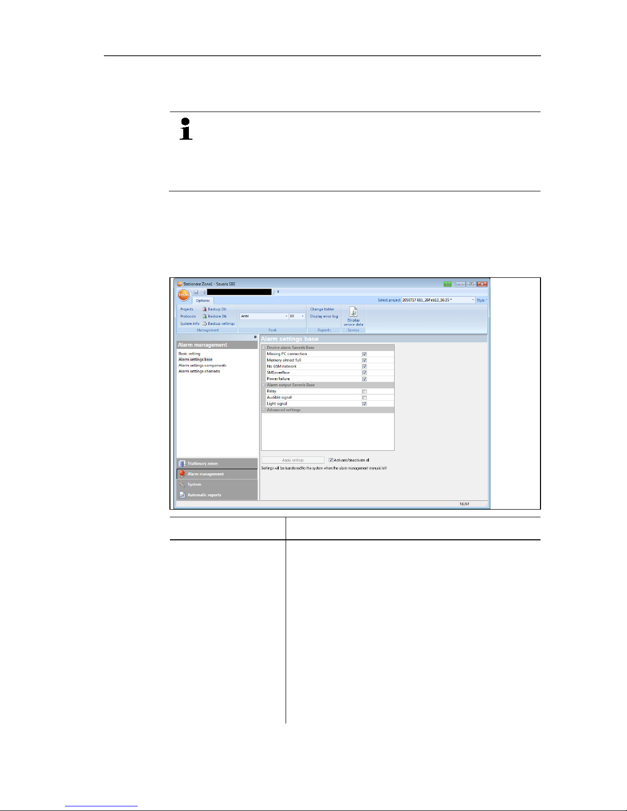
6 Using the product
98
6.4.2. Setting up base alarms
Any configuration changes are only transferred to the
probe/base once you have exited the Alarm management
menu!
You should therefore exit the Alarm management menu
after editing.
1. Click on Alarm management in the navigation area.
- The data area shows the sub-menus Base alarm settings,
Component alarm settings, Channel alarm settings.
2. Click on Base alarm settings.
- The Base alarm settings are shown in the display area.
Display Explanation
Device alarm
Saveris Base
Setting options for the base alarms
Missing PC connection: no response from
the PC
Memory almost full: alarm when the base
memory overflows.
No GSM network: alarm when there is no
GSM connection.
SMS overflow: alarm when an error occurs
in SMS transmission.
Power failure: alarm when the base power
supply fails.
Page 99

6 Using the product
99
Alarm output
Saveris Base
Relay
Audible signal
Light signal
Advanced settings Radio interference (stationary) [min]
Network interference [min]
Radio interference (mobile) [h]
Apply settings
Saves the alarm settings.
Activate/deactivate
all
Activates all available alarm settings.
3. Carry out alarm settings for the base.
4. Click on Apply Entries.
5. Exit Alarm Management menu.
- Alarm settings are transferred to the devices.
Pos: 128 /TD/Produkt verwenden/testo Saveri s/04 Alarme konfiguri eren/SBE/01 Alarm vorkonfigur ieren - 01 Gruppen SBE @ 15\mod_ 1381828452982_79.d ocx @ 178253 @ 3455555455555 @ 1
6.4.3. Setting up alarm groups
6.4.3.1. Components
Any configuration changes are only transferred to the
probe/base once you have exited the Alarm management
menu!
You should therefore exit the Alarm management menu
after editing.
1. Click on Alarm management in the navigation area.
- The data area shows the sub-menus Base alarm settings,
Component alarm settings, Channel alarm settings.
2. Click on Component alarm settings.
- The probe alarm settings are shown in the display area.
Page 100
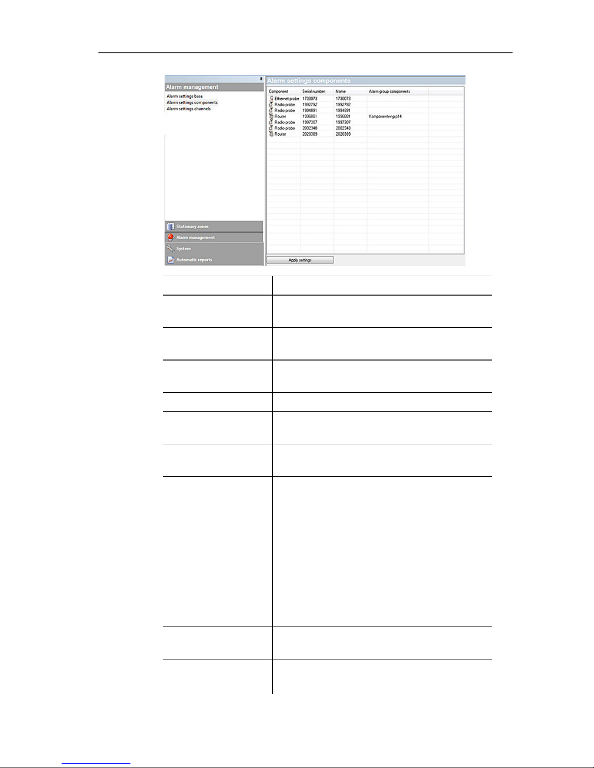
6 Using the product
100
Designation Description
[Insert into new
group]
Creates a new alarm group.
[Move to] Move components/channel to another
alarm group.
[Remove from
group]
Removes the components/channel from
the specified alarm group.
[Delete this group]
Deletes the entire alarm group.
[Apply to all] Applies an alarm group to all
components/channels.
Component list List of the available components and their
affiliation to the selected alarm group.
Group alarm
settings
Enter the group name.
System settings
Output of system alarms: alarm
activation for notification when there is a
connection problem, LoBat and power
failure
Alarm conditions: trigger acknowledged
alarms after [min]
Alarm output Saveris Base: settings for
relays, audible signal and light signal.
[Apply entries] Saves the alarm settings of an alarm
group.
Activate/deactivate
all
Activates all available alarm settings.
 Loading...