

Page 1
testo EasyClimate · Software
Instruction manual
Page 2

1 Contents
1 Contents
1 Contents ................................................................................................... 3
1.1. About this document ........................................................................ 5
2 Specifications .......................................................................................... 5
2.1. Use .................................................................................................. 5
2.2. System requirements ....................................................................... 6
3 First steps ................................................................................................ 6
3.1. Installing the software/driver ............................................................ 6
3.2. Starting the software ........................................................................ 7
4 Using the product .................................................................................... 7
4.1. Initial page menu ............................................................................. 7
4.2. Settings menu .................................................................................. 9
4.2.1. Configuration ................................................................................................... 9
4.2.1.1. Program tab ....................................................................................... 9
4.2.1.2. Units tab .......................................................................................... 10
4.2.1.3. Own data tab ................................................................................... 10
4.2.1.4. Data backup tab .............................................................................. 10
4.2.2. System information ........................................................................................ 11
4.2.3. Copyright ....................................................................................................... 12
4.3. Instrument menu ............................................................................ 12
4.3.1. Connection manager ...................................................................................... 12
4.3.2. Configuration ................................................................................................. 13
4.3.2.1. Instrument tab ................................................................................. 14
4.3.2.2. Configuration tab (testo 835 only) .................................................... 14
4.3.2.3. Energy management tab (testo 480 only) ........................................ 15
4.3.2.4. Display language tab ....................................................................... 15
4.3.2.5. Emission level table tab (testo 835 only) .......................................... 15
4.3.2.6. Password security tab (testo 480 only) ............................................ 15
4.3.2.7. Probe tab (testo 480 only) ............................................................... 16
4.3.2.8. Printout tab (testo 480 only) ............................................................. 17
4.3.3. Online measurement ...................................................................................... 17
4.3.3.1. Measurement values tab ................................................................. 18
4.3.3.2. Display tab ....................................................................................... 18
4.3.3.3. Chart tab.......................................................................................... 19
4.3.3.4. Display order tab ............................................................................. 19
4.4. Archive menu ................................................................................. 19
4.4.1. Explorer ......................................................................................................... 20
4.4.1.1. Adding a folder ................................................................................ 20
4.4.1.2. Adding a measurement location (testo 480 only) ............................. 20
4.4.1.3. Adding a measuring point (testo 480 only) ....................................... 21
4.4.1.4. Adding a measuring program (testo 480 only) ................................. 21
4.4.1.5. Copying folders/measurements ....................................................... 21
4.4.1.6. Further functions .............................................................................. 21
3
Page 3

1 Contents
4.4.2. Displaying measurements.............................................................................. 22
4.4.2.1. Information tab ................................................................................ 22
4.4.2.2. Chart tab ......................................................................................... 22
4.4.2.3. Measurement values tab ................................................................. 23
4.4.2.4. Report templates tab ....................................................................... 23
4.4.2.5. Report tab ....................................................................................... 24
4.4.2.6. Report designer tab ......................................................................... 24
4
Page 4
1.1. About this document
Use
> Please read this documentation through carefully and
familiarize yourself with the product before putting it to use. Pay
particular attention to the safety instructions and warning advice
in order to prevent injuries and damage to the products.
> Keep this document to hand so that you can refer to it when
necessary.
> Hand this documentation on to any subsequent users of the
product.
Knowledge of Windows® operating systems is required
when working with the software.
2 Specifications
Symbols and writing standards
Representa-
Explanation
tion
Note: Basic or further information.
1. ...
2. ...
Action: more steps, the sequence must be
followed.
> ... Action: a step or an optional step.
- ... Result of an action.
Menu
[OK]
Elements of the program interface.
Buttons of the program interface.
... | ... Functions/paths within a menu.
“...” Example entries
2 Specifications
2.1. Use
The testo EasyClimate Software configuration and analysis
software enhances the functionality of the testo 480 and testo 835
instruments with many useful functions:
• Instrument configuration via software.
• Customer and measurement data management.
• Data import from and data export to instrument.
5
Page 5

3 First steps
• Creating, saving and printing measurement protocols from
imported data.
2.2. System requirements
• Commenting on measurement values.
Administrator rights are required for installation.
Operating system
The software will run on the following operating systems:
• Windows® XP ServicePack 3 (SP3)
• Windows Vista
• Windows 7
• Others: on request
Computer
The computer must meet the requirements of the corresponding
operating system. The following requirements must additionally be
fulfilled:
• Interface USB 1.1 or higher
• Internet Explorer 5.0 SP1 or higher
Date and time settings will be automatically accepted by
the PC. The administrator must make sure that the system
time is regularly compared with a reliable time source and
adjusted, if necessary, to ensure authenticity of the
measurement data.
3 First steps
3.1. Installing the software/driver
1. Insert the program CD into the CD-ROM drive of the computer
or
download the program (www.testo.com/download-center)
and unpack the zip file using a suitable compression program.
2. Start the file TestoSetup.exe.
3. Follow the instructions of the installation wizard.
When installing under Vista, please pay attention to the following
steps during the installation process:
• The window User account control is opened:
> Click on [Next].
6
Page 6
• The window Windows Security is opened:
> Choose Still install this driver software.
4. Click on [Complete] to complete the software installation.
After completion of the software installation, the instrument must be
connected to the PC to continue with the driver installation.
5. Use the USB-cable to connect the instrument to the PC.
3.2. Starting the software
- The connection will be set up.
4 Using the product
Starting the EasyClimate software
The software user interface is opened in the language
of the operating system, if this is supported. If the
operating system language is not supported, the user
interface is in English.
> Click on [Start] | Programs (Windows XP) or All Programs
(Windows Vista, Windows 7) | Testo | testo EasyClimate
Software.
On Windows Vista, the window User account control
is opened when the software is started the first time.
> Click on Accept.
> Enter the licence key, see program CD packaging (testo 480) or
4 Using the product
the back of the instruction manual (testo 835).
Help button
The help symbol opens/closes the help bar. This button
is available in all menus except the Initial page menu.
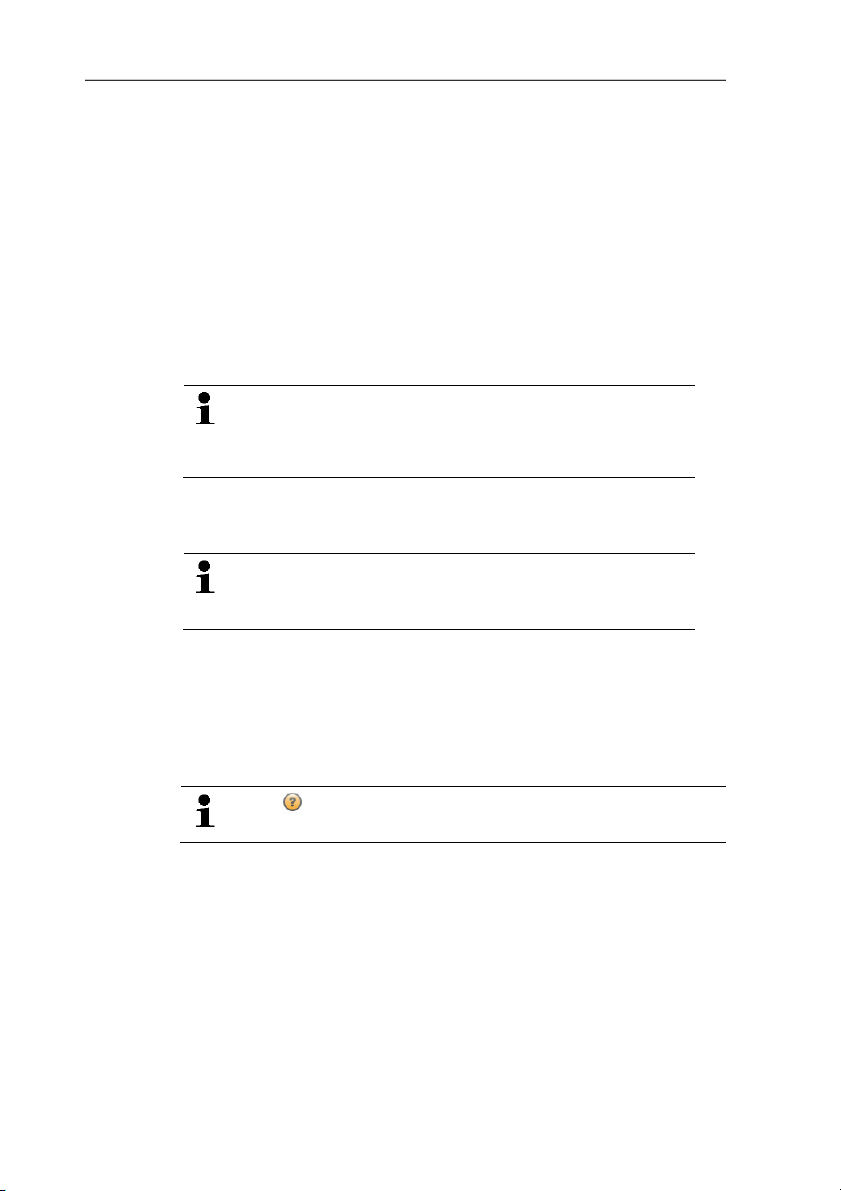
4.1. Initial page menu
After starting testo EasyClimate Software, the start screen will
appear.
7
Page 7
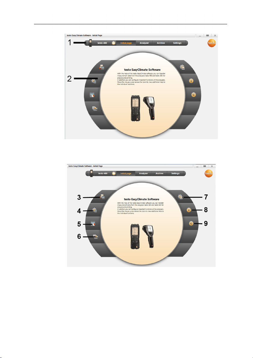
4 Using the product
1 Menu bar with status information (left)
2 Quick access with preview screen
3 Connection manager
4 Configuration of instrument
5 Online measurement
6 Manage archived measurements
7 Program configuration
8 System information
9 Copyright
8
Page 8
4.2. Settings menu
Via the Settings menu, you can open the Configuration, System
information and Copyright menus.
4.2.1. Configuration
4 Using the product
> Choose Initial page| Program configuration
or
> Settings | Configuration.
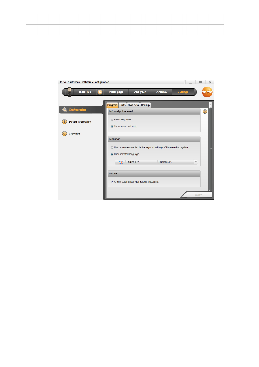
4.2.1.1. Program tab
> Left navigation panel: Choose Show only icons or Show
icons and texts | [Apply].
> Language: Choose Use language selected in the regional
settings of the operating system. or User selected language
| [Apply].
> Program update: Choose Check automatically for software
updates | [Apply].
9
Page 9

4 Using the product
4.2.1.2. Units tab
> Select the required unit for the individual measurement
parameters | [Apply].
> [ISO units] | [US units]: reset all units to ISO or US | [Apply].
4.2.1.3. Own data tab
> Own data: enter/change address data | Change logo [Apply].
see Information tab, page 22
4.2.1.4. Data backup tab
Backup data
1. Specify the directory for data backup: click [Browse] .
2. Click [Perform backup now].
- Folder FullBackup[DateTime] is created.
Set reminder for data backup
1. Specify the directory for data backup: click [Browse].
2. List field: specify the cycle for automatic data backup | [Apply].
- When the software is started, a reminder that backup is due is
given in a set cycle.
Restore backed-up data
✓ Data has been backed up.
1. Open the following folder in the File Explorer:
10
Page 10

• Data backup directory (path see Settings | Configuration |
Data backup)
• Data directory (path see Settings | System information |
PC)
2. Close the software.
3. Copy contents of the folder that are to be restored
FullBackup[DateTime], from the data backup directory into the
data directory.
4. Open the software.
4.2.2. System information
The System information menu has 3 tabs showing important
information about the PC used and the software. It is useful to have
this information to hand when contacting our hotline as it will help in
diagnosing errors.
4 Using the product
> Choose Settings | System information.
Executable actions
> [Data directory...]: Call up directory.
11
Page 11
4 Using the product
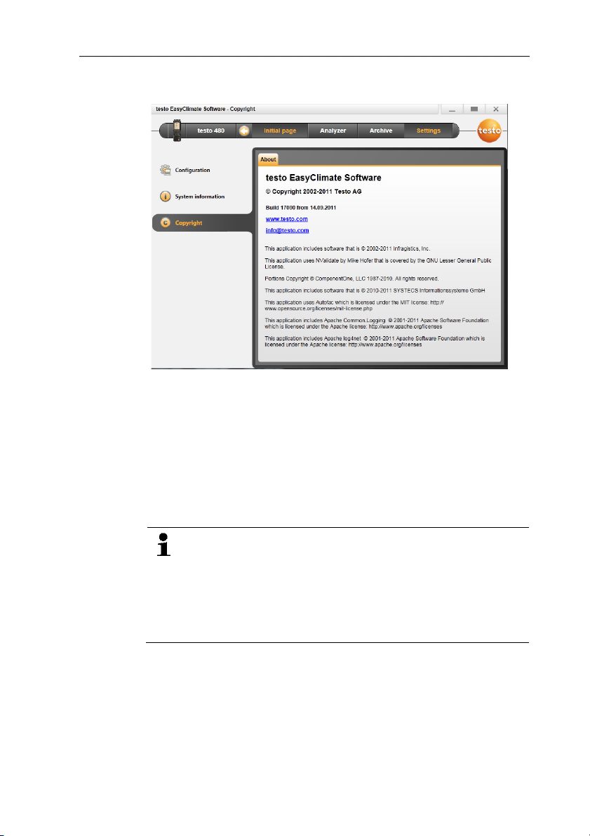
4.2.3. Copyright
> Choose Settings | Copyright.
- The About tab is opened.
4.3. Instrument menu
4.3.1. Connection manager
12
✓ Instrument connected to PC.
An instrument connected to the PC is automatically
connected to the software. If several instruments are
connected to the PC, the required instrument can be
connected in the connection manager.
testo 480 only: The SD card can be connected in the same
way as an instrument. However, some menu options (e.g.
Instrument) cannot be selected.
> Initial page | Connection manager
or
> Instrument | Connection manager.
- Instruments are displayed with picture and type designation.
> Choose the instrument and click on [Connect].
Page 12

4 Using the product
Only one instrument can be connected at a time.
- The instrument appears in the status display to the left of the
menu bar.
- The button [Connect] changes to [Disconnect].
If not possible to connect:
On Windows XP:
> Start | Settings | System control | System | Hardware |
Device manager.
On Windows Vista:
> Start | System control | System and maintenance | Device
manager.
On Windows 7:
> Choose Start | System control | System and security |
System | Device manager.
4.3.2. Configuration
✓ An instrument is connected to the testo EasyClimate Software
and displayed in the status bar.
13
Page 13

4 Using the product
> Choose Initial page | Configuration of instrument
or
> Instrument | Configuration.
4.3.2.1. Instrument tab
The Instrument tab shows important information about the
connected instrument.
> [Synchronise now]: Transfer PC date and time to the
instrument.
> [Synchronise units]: Transfer units set in the Settings menu
manually to the connected instrument or probes.
> [Firmware update] (testo 480 only): Import the downloaded
update firmware file to the instrument.
> [Factory reset]: Carry out a factory reset of the instrument.
4.3.2.2. Configuration tab (testo 835 only)
> Disable/enable alarm: disable/enable Beeper checkbox | [Save].
> Disable/enable alarms and set alarm thresholds: disable/enable
Infrared, Thermocouple, Surface moisture or Dewpoint
distance checkbox and enter limits | [Save].
> Disable/enable laser: disable/enable Laser checkbox | [Save].
> Set display brightness: move slider | [Save].
14
Page 14

4.3.2.3. Energy management tab (testo 480 only)
> Switch off instrument automatically: enter required time frame |
[Save].
> Switch off display light in battery operation: enter required time
frame | [Save].
> Set display brightness: move slider | [Save].
4.3.2.4. Display language tab
The available languages for texts in the instrument are displayed.
> Select language | [Save].
4.3.2.5. Emission level table tab (testo 835 only)
A separate emission level table is saved on the instrument
for each user language. Changes to the table only relate to
the relevant selected language.
When the tab is opened, the emission level table is automatically
read out from the instrument.
> Change the designation: triple-click on the cell | make changes |
[Write to device]
> Add to material: enter designation and emission level in the last
line | [Write to device]
> Read out emission level table again from the instrument: [Read
from device].
> Save emission level table as an XML file to the PC: [Save as].
> Load emission level table saved on the PC: [Read from file].
4 Using the product
4.3.2.6. Password security tab (testo 480 only)
When password security is enabled, all of the following functions
can only be carried out on the instrument by entering the password:
• Instrument factory reset
• Probe reset
• Firmware update
• Change/deactivate password
• Probe name
15
• Humidity adjustment
If you forget the password, it can only be reset by Testo
Service.
> Enter password | Re-enter password | [Save].
Page 15
4 Using the product
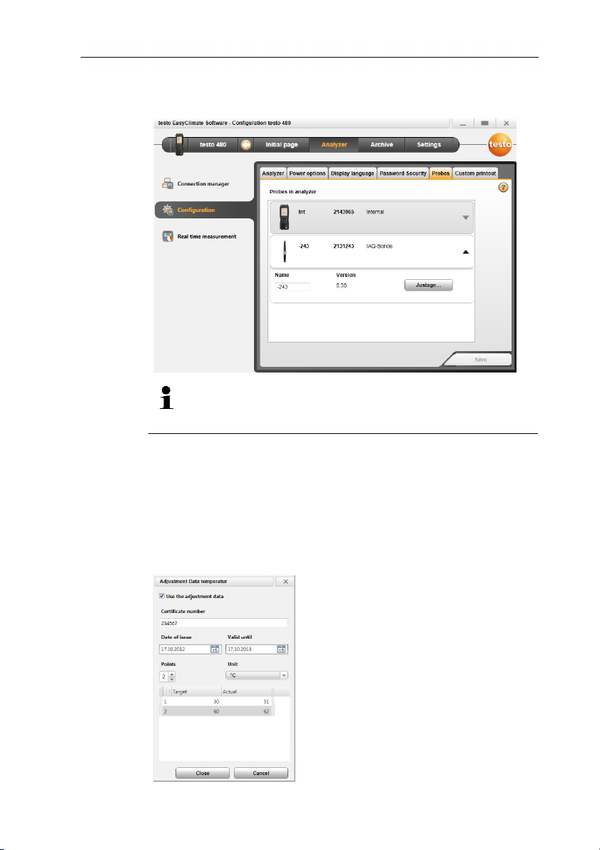
4.3.2.7. Probe tab (testo 480 only)
The probe types connected to the instrument are displayed.
The probe name of any connected probe can be changed
and calibration data from the calibration protocol stored in
the probe.
Select probe type [▼].
> Press [Adjustment]
- Selection window appears.
> Select unit for the adjustment | [Next]
> Activate [Use adjustment data], enter: Certificate number |
Date of issue | Valid to | Points | Unit | Target- and Actual
value | [Close] | [Save].
- The adjustment data is stored in the instrument.
16
Page 16
Once the calibration data has been entered, this is stored in
the probe permanently. The probe takes deviations into
account automatically during measurement, thereby
generating a zero-error display.
4.3.2.8. Printout tab (testo 480 only)
On the Printer texts tab, the address lines, the footer and the logo
can be set up for testo 480 instrument report printouts.
> Enter print texts in the text input fields | [Save].
4.3.3. Online measurement
> Select required logo | [Save].
Electrostatic charging may destroy communication between
the instrument and the PC/laptop. You should therefore
integrate all components into the equipotential bonding
(earthing) before carrying out measurements, especially in
the case of online measurements (instrument connected to
PC/laptop) or when using the mains unit as a power supply.
Observe the system safety information.
Using the Online measurement menu, a measurement can be
carried out, during which the instrument is controlled by the PC.
The measurement values are transferred directly to the PC and
displayed.
4 Using the product
> Choose Initial page| Online measurement
or
> menu Instrument| Online measurement.
17
Page 17

4 Using the product
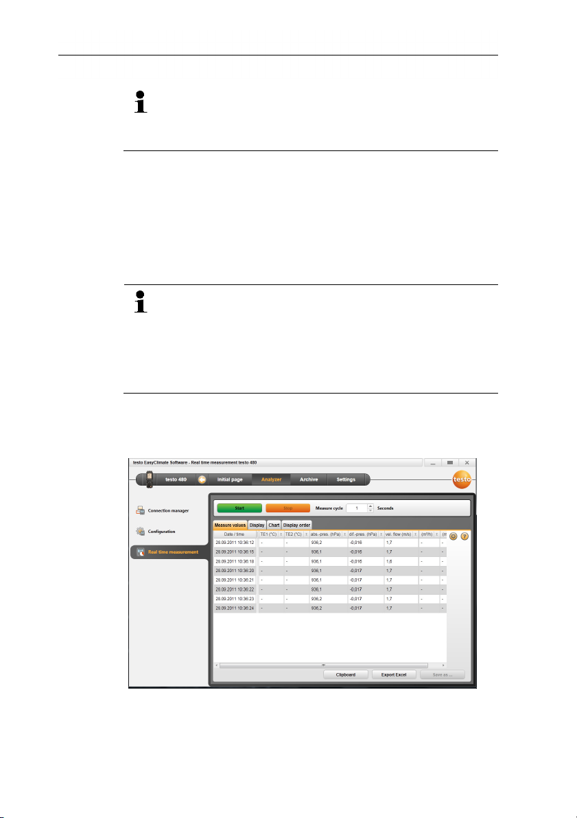
Carrying out the online measurement
Only the parameters and measuring units activated on the
Display order tab are displayed.
1. Set Measure cycle and emission level (testo 835 only).
2. Set display sequence.
3. Start online measurement: [Start].
- The measurement values are displayed.
4. End online measurement: [Stop].
- The online measurement is stopped.
Saving measuring values from online measurement
1. Display measuring values.
2. Choose between [Clipboard], [Export Excel] and [Save as
…].
• Clipboard: the measuring values are stored in the
clipboard, for inserting into any file.
• Export Excel: the measuring values are exported in
*.xls or *.xlsx format.
• Save as…: the measuring values are stored in the
software's archive. Saving is only possible with a
standard measurement program.
4.3.3.1. Measurement values tab
> Measurement values: show table with all measurement
channels and date/time of the single measurements.
Executable actions
> [Save as ...]: save measurement values.
> [Export Excel]: export measurement values to Microsoft Excel
(Microsoft Excel 2000 or higher required!).
> [Clipboard]: export measurement values to the clipboard (tab
stop-separated text file).
4.3.3.2. Display tab
- Display: display fields with all measurement channels. The
current measurement values are displayed.
Executable actions
> Close/open display bar: press [].
> During a measurement, the mean value, maximum or
minimum can be displayed instead of the actual values.
18
Page 18

> Change size (zoom) of the display fields: move slider.
4.3.3.3. Chart tab
- Chart: Measurement chart with 16 selectable measurement
channels and automatic scaling of the time axis.
Executable actions
> Close/open display bar: press [].
> Set chart properties (displayed channels, line colour, scale,
limits).
> [Save bitmap]: save chart as a file.
4.3.3.4. Display order tab
The available measurement channels are displayed in the
Available channels area. Only the parameters and measuring
units that are present in the current display order of the instrument
are available.
The measurement channels displayed on the PC during online
measurement are displayed in the Selected channels area.
Set display order
> Add/delete measurement channels: [Add >], [Add all >], [<
Delete] or [< Delete All].
> Set the order of the measurement channels: select
measurement channel | [Up] or [Down].
4 Using the product
4.4. Archive menu
✓ An instrument is connected to the testo EasyClimate Software
and is displayed with its status information (left) in the menu
bar.
This menu is used to archive measurements within a folder
structure. If an instrument is connected and if there are also
measurements on the instrument, these measurements can be
copied from the instrument to the archive, and the folder structure
on the instrument can be changed.
19
Page 19
4 Using the product
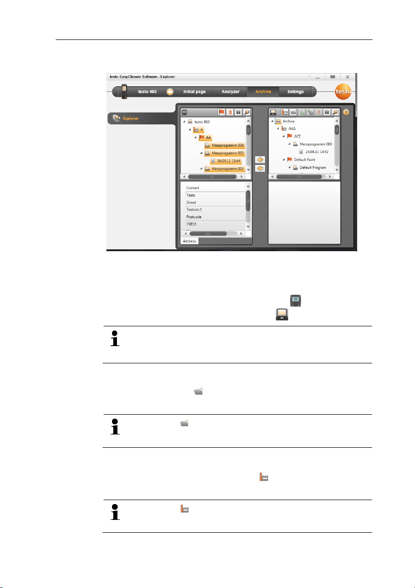
4.4.1. Explorer
> Menu Initial page | Manage archived measurements.
or
Menu Archive | Explorer.
- The instrument memory is displayed under (left window),
and the PC memory is displayed under (right window).
The functions described below can, in some cases, only be
executed on the instrument memory or the PC memory,
depending on the connected instrument.
4.4.1.1. Adding a folder
> Add folder: press [] symbol.
- Folder New folder is created.
Press the [] symbol again to create another folder.
If a folder text field is selected, the folder can be renamed.
4.4.1.2. Adding a measurement location (testo 480 only)
1. Add measurement location: press [] symbol.
20
- Folder New measurment location is created.
Press the [] symbol again to create another folder.
If a folder text field is selected, the folder can be renamed.
Page 20

2. If the folder is activated, information on the measurement
location can be entered on the Address tab.
4.4.1.3. Adding a measuring point (testo 480 only)
1. Add measuring point: press [] symbol.
- Folder New measuring point is created.
Press the [] symbol again to create another folder.
If a folder text field is selected, the folder can be renamed.
2. If the folder is activated, information on the measuring point can
be entered on the Measuring point and Channel geometry
tabs.
4.4.1.4. Adding a measuring program (testo 480 only)
1. Add measuring program: press [] symbol.
- Folder New measuring program is created.
Press the [] symbol again to create another folder.
If a folder text field is selected, the folder can be renamed.
2. If the folder is activated, information on the measuring program
can be entered on the Measuring program tab.
4 Using the product
4.4.1.5. Copying folders/measurements
1. Select folder or measurement: move the cursor to the required
symbol and select it by clicking on it (highlighted orange).
2. Move the cursor to the target folder and select it by clicking on it
(highlighted orange).
3. Copy selected folder or measurement from the instrument to the
archive: press symbol [].
or
Copy selected folder or measurement (testo 480 only) from the
archive to the instrument: press symbol [].
4. Save instrument data or archive: press [] symbol.
4.4.1.6. Further functions
• Create VAC measuring program: press [].
• Create turbulence measuring program: press [].
• Create WBGT measurement: press [].
• Create PMV/PPD measurement: press [].
21
Page 21

4 Using the product
• Remove folder: press [] symbol.
• Import measurements: press [] symbol.
• Search for data: press [] symbol.
• Display selected measurement: press [] symbol.
• Export selected measurement: press [] symbol.
4.4.2. Displaying measurements
Only measurements from the PC memory can be
displayed. Data from the instrument must therefore first be
copied to the PC.
1. Menu Initial page | Manage archived measurements.
or
Menu Archive | Explorer.
2. Under (right window), double-click on .
- The Display measurement data module is opened.
4.4.2.1. Information tab
The Information tab shows meta data for the measurement. A
comment can be entered.
4.4.2.2. Chart tab
The Chart tab gives the measurement values in a graphical
display.
22
Page 22

Executable actions
> Close/open display bar: press [].
> Set chart properties (displayed channels, line colour, scale,
limits).
> [Save bitmap]: save chart as a file.
4.4.2.3. Measurement values tab
The individual measurement values are shown in table form on the
Measurement values tab.
Executable actions
> [Export Excel]: export measurement values to Microsoft Excel
(Microsoft Excel 2000 or higher required!).
> [Clipboard]: export measurement values to the clipboard (tab
stop-separated text file).
> Add a comment:
1. Click on the measurement value to which you want to add a
comment.
- The Measurement comment window opens.
2. Enter comment.
3. Click on [OK].
4. Click on [Save comments].
- The comment is displayed as a green triangle (or a green circle
on the chart). The comment appears when the mouse rolls over
it.
> Change comment: You can click on the comment to edit it.
4 Using the product
4.4.2.4. Report templates tab
The existing report templates may not be edited or deleted.
Create a copy of the required report template in order to
edit it and to be able to use the executable actions.
There are various report templates available on the Report
templates tab. These templates can be renamed, deleted or
edited, or a new one created.
23
Page 23

4 Using the product
Executable actions
> [New]: create a new report template
> [Change]: edit activated report template in the report designer
> [Rename]: rename template
> [Delete]: delete created template
> [Copy]: copy report template
4.4.2.5. Report tab
The Report tab shows the report for the measurement in the
selected report template. The report can be saved and printed.
4.4.2.6. Report designer tab
On the Report designer tab, the report templates for printing
measuring protocols can be changed to suit the user's specific
requirements.
24
Page 24

4 Using the product
The displayed properties apply to the report template, which is
identified on the Report template tab.
•
Text field: text is inserted in the report field as it is entered.
• Data field: the value stored in the database (measurement
value, customer or system data) of the selected data field is
inserted into the report field.
Choose field from database: [...].
• Graphic: the selected graphic is inserted in the report field.
Select graphic: [File...] | select file | [Open].
• PMV/PPD: The PMV/PPD measurement chart is inserted.
• Chart (measurement data): the measurement values stored
in the database for the measuring protocol are inserted into the
report field as a graphic.
Enter the parameters.
• Table: the measurement values stored in the database for
the measuring protocol are inserted into the report field in table
form.
This function is only available if Text field or Data field is
selected as the field type.
25
Page 25

4 Using the product
•
used for all text and data fields.
•
Special font: a font other than the default font is used.
Select font: [Font...] | select values | [OK].
•
Alignment.
• Colour: choose font colour.
• Background colour: select background colour.
• Border: select border properties for the report field.
• Enter or set page properties.
•
• : scroll forward/back in the report template.
Alignment: select the alignment in the text field under
Preview: switch display from data field to content.
Default font: the set default font is
26
 Loading...