

Page 1
testo CU-2
User Manual
Page 2

2
Page 3

Content
3
Content
1 Declaration of Warranty ............................................................................................... 6
1.1. Type of Designation ....................................................................................................................... 6
1.2. Manufacturer ................................................................................................................................ 6
1.3. Warranty ....................................................................................................................................... 6
2 Precautions ................................................................................................................... 6
2.1. Foreword ...................................................................................................................................... 6
2.2. Liabilities ....................................................................................................................................... 6
2.2.1. Liability to Content............................................................................................................... 7
2.3. Copyright © .................................................................................................................................. 7
3 Safety ............................................................................................................................ 7
3.1. Risk Types...................................................................................................................................... 7
3.1.1. Electrical Safety ................................................................................................................... 7
3.2. Labels and Explanations ................................................................................................................. 7
4 System Overview .......................................................................................................... 8
4.1. Introduction .................................................................................................................................. 8
4.1.1. testo CU-2 Digital Control Unit ............................................................................................. 8
4.1.2. testo NanoMet Software ...................................................................................................... 8
4.2. Definitions ..................................................................................................................................... 8
4.3. Abbreviations, Units and Symbols .................................................................................................. 8
4.4. The System .................................................................................................................................. 10
4.4.1. Overview ........................................................................................................................... 10
4.4.2. Functionality ...................................................................................................................... 10
4.5. Control Elements and Connections .............................................................................................. 11
4.5.1. Front and Rear View .......................................................................................................... 11
4.5.2. Additional Analog and Digital In- and Output Connector 20) ............................................... 12
5 Installation and Setup ................................................................................................. 12
5.1. Hardware Setup........................................................................................................................... 12
5.2. Windows Embedded and Network Setup ..................................................................................... 12
5.2.1. Windows Embedded Login ................................................................................................. 12
5.2.2. Network Settings ............................................................................................................... 13
5.3. testo NanoMet Software Startup and Operation Mode Selection ................................................. 13
5.3.1. Manual Operation Mode .................................................................................................... 13
5.3.2. Software Control Mode ...................................................................................................... 14
5.3.3. Remote Computer Software Control Mode ........................................................................ 14
5.4. AK Host Remote Control Mode .................................................................................................... 15
6 testo NanoMet Operation ........................................................................................... 17
6.1. Main Measurement Tab .............................................................................................................. 17
6.1.1. Pause State ........................................................................................................................ 17
6.1.2. Standby State .................................................................................................................... 17
Page 4

Content
4
6.1.3. Measurement state ........................................................................................................... 18
6.1.4. Leak Test ........................................................................................................................... 18
6.1.5. Zero Test............................................................................................................................ 18
6.2. Measurement Configuration ........................................................................................................ 19
6.2.1. UN-ECE R83 Measurement and Test Cycle Definition .......................................................... 19
6.2.2. General Measurement Settings .......................................................................................... 20
6.3. System Configuration .................................................................................................................. 20
6.3.1. Measurement Instruments................................................................................................. 20
6.3.2. Dilution Instruments .......................................................................................................... 21
6.3.3. AK Interfaces ..................................................................................................................... 22
6.4. Analog Input and Output Signals Configuration ............................................................................ 22
6.4.1. Analog In ........................................................................................................................... 23
6.4.2. Analog Out......................................................................................................................... 23
6.4.3. Digital Out / Errors ............................................................ Fehler! Textmarke nicht definiert.
6.5. PNC Tab....................................................................................................................................... 24
6.6. testo NanoMet Control Panel and CPC Window ........................................................................... 24
6.6.1. testo NanoMet Control Panel ............................................................................................. 24
6.6.2. CPC Window ...................................................................................................................... 25
7 AK Host Operation ...................................................................................................... 25
7.1. AK Software Integration............................................................................................................... 25
7.2. AK Interfaces Specifications ......................................................................................................... 25
7.2.1. Serial Interface ................................................................................................................... 25
7.2.2. TCP/IP Interface ................................................................................................................. 26
7.3. AK Protocol Specification ............................................................................................................. 26
7.3.1. AK Command Telegram ...................................................................................................... 26
7.3.2. AK Response Telegram ....................................................................................................... 26
7.3.3. General AK Protocol Description ........................................................................................ 27
7.3.4. Handling of Certain Conditions ........................................................................................... 27
7.4. List of All AK Commands .............................................................................................................. 28
7.4.1. Control Commands – 'S' ..................................................................................................... 28
7.4.2. Write Commands – 'E' ........................................................................................................ 28
7.4.3. Read Commands – 'A' ........................................................................................................ 28
7.5. Descripton of All AK Commands ................................................................................................... 29
7.5.1. Control Commands – 'S' ..................................................................................................... 29
7.5.2. Write Commands – 'E' ........................................................................................................ 30
7.5.3. Read Commands – 'A' ........................................................................................................ 32
7.5.4. AK Errors List ..................................................................................................................... 34
8 Electrical Connections ................................................................................................. 35
8.1. Mains Supply ............................................................................................................................... 35
8.2. Dilution/Conditioning Devices...................................................................................................... 36
8.3. Analog/Digital Interface ............................................................................................................... 36
8.4. Standard Embedded Computer Ports ........................................................................................... 37
9 Maintenance and Calibration ...................................................................................... 38
Page 5

Content
5
9.1. Storage, Acclimatization .............................................................................................................. 38
9.2. Operation Environment Requirements......................................................................................... 38
10 Appendix ..................................................................................................................... 39
10.1. Extent of Delivery ........................................................................................................................ 39
10.2. Specification, Technical Data ....................................................................................................... 39
10.3. Designation of All testo CU-2 Digital Control Unit Operating Elements ......................................... 40
Page 6

1 Declaration of Warranty
6
1 Declaration of Warranty
Manual Version History:
Version: V1.03
Date: November 2018
1.1. Type of Designation
This user manual refers to the instrument and software type and version as listed below. It
replaces all previously dated user manuals for this instrument.
Type: testo CU-2
1.2. Manufacturer
Testo SE & Co. KGaA Tel: +49 7653 681 5062
Testo-Strasse 1 Fax: +49 7653 681 95062
79853 Lenzkirch web: www.testo.com
Germany email: info@testo.de
For technical support contact your local service contractor or Testo techsupport.
email: support-nanoparticle@testo.de
1.3. Warranty
Testo SE & Co. KGaA warrants that this product adheres to the specified properties for a period
of twelve (12) months from the date of delivery.
Excluded from the warranty are all parts subjected to normal wear as any fuses, batteries or
other consumable parts. Also excluded are: Defects resulting from abnormal use, in particular
outside the intended purpose; lack of maintenance; improper use or malicious damage. Warranty
is void if actions are carried out which are not described in the documentation nor authorized by
Testo SE & Co. KGaA.
Testo SE & Co. KGaA does not provide any warranty on finished goods manufactured by others.
Only the original manufacturer's warranty applies.
There are no user-serviceable parts inside testo CU-2 and some very sensitive parts. Do not
open your testo CU-2, as you may damage it. Warranty is voided if the case is opened and
warranty-seal is broken.
Parts repaired or replaced as a result of repair services are warranted to be free from defects in
workmanship and material, under normal use, for 90 days from the date of shipment.
2 Precautions
2.1. Foreword
This manual guides you through the installation, starting up, operation and maintenance
procedures of the testo CU-2. In detail you will find information about the system as
• safety
• functionality of the testo CU-2, technical information and specifications
• installation of the testo CU-2 and accessories
• handling, operation, maintenance and troubleshooting
Follow the instructions provided by this manual for safe and proper operation of the testo CU2 Digital Control Unit.
Before installing and operating the testo CU-2, the operator or service has to
read carefully this manual. For improper function, damages or injuries caused
by ignoring the instructions by this manual no liabilities are accepted.
2.2. Liabilities
Testo SE & Co. KGaA accepts no liability to improper function or injury caused by
• neglecting the instructions provided by this manual or instructed person.
• improper installation, operation, application, or maintenance.
• operation by untrained staff.
Page 7
3 Safety
7
• any technical modification not carried out by Testo SE & Co. KGaA or an authorized
service partner.
For operating the testo MD19-3E Rotating Disk Diluter and testo ASET15-1 Air
Supply / Evaporation Tube together with testo CU-2 Digital Control Unit, refer to the related user
manuals.
2.2.1. Liability to Content
The content of this manual is generated with most accurateness. Testo SE & Co. KGaA does not
guarantee completeness, correctness and being up to date. Testo SE & Co. KGaA reserves the
right to revise the content of the manual at any time and without notice.
2.3. Copyright ©
All work and contents done or generated by Testo SE & Co. KGaA are subject of the German
copyright © and law for intellectual property. This copyright includes all specification data of the
instrument or part of it, electrical and fluidic and mechanical schematics, pictures, diagrams and
text. Copying, editing, publishing or any other utilisation requires a written agreement of
Testo SE & Co. KGaA.
3 Safety
3.1. Risk Types
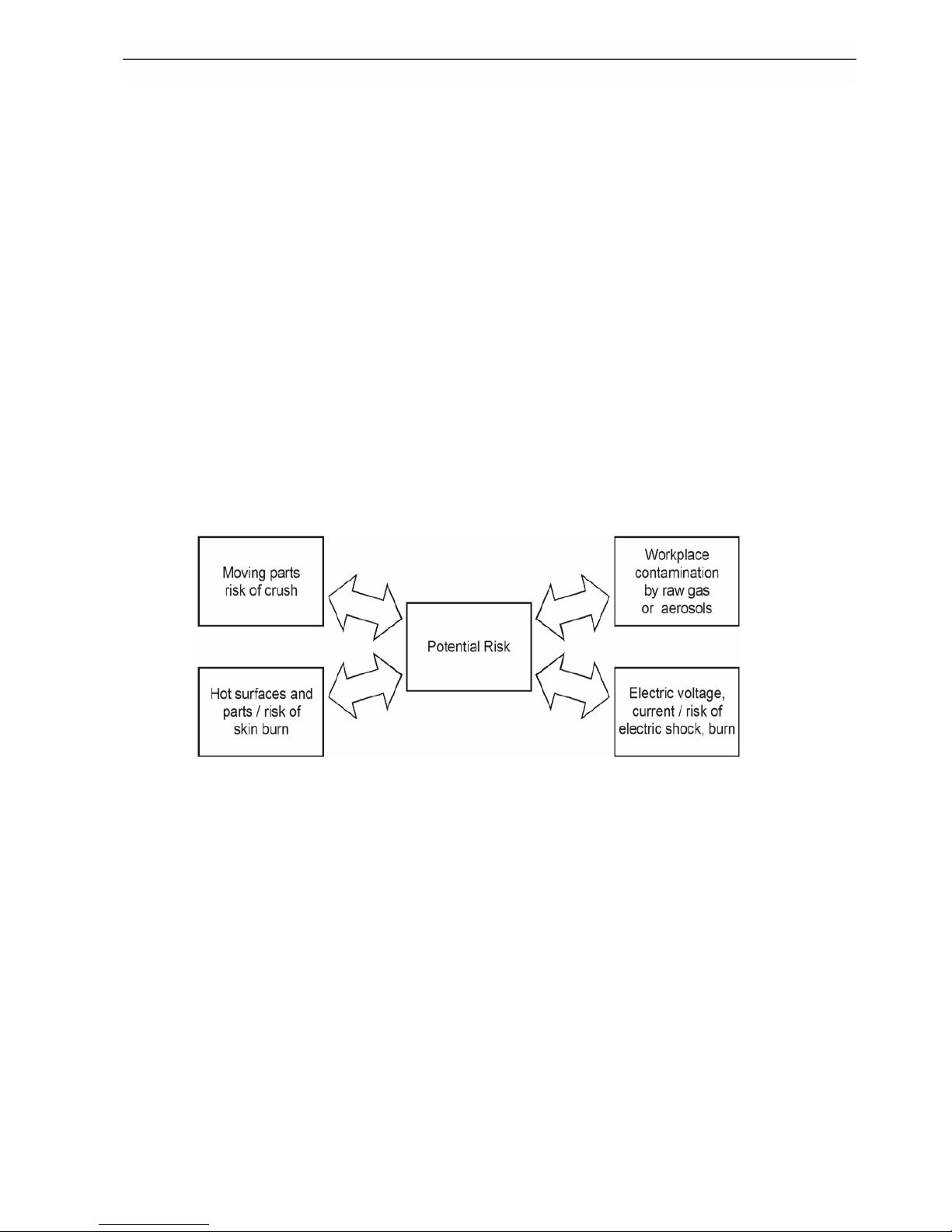
The diagram in Fig. 3.1 shows typical risks that could cause damage or injury while handling the
testo MD19-3E Rotating Disk Diluter or testo ASET15-1 Air Supply / Evaporation Tube. These
risks may also occur if these or other devices are used in combination with testo CU-2.
Fig. 3.1: risk types
Refer to the user manuals of the devices connected to the testo CU-2 digital control unit to learn
more about the risks which may occur operating them.
3.1.1. Electrical Safety
When in operation any electrical equipment can produce dangerous voltages. Failure to observe
the warnings may result in serious injury or damage. It is, therefore, mandatory that only suitably
qualified personnel use this instrument. Satisfactory and safe operation of this instrument calls for
proper handling in transportation, storage, installation as well as careful control and maintenance.
3.2. Labels and Explanations
Listed labels, Caution and Warning are explained in general, and the further specific labels refer
to type of hazard and danger.
Page 8
4 System Overview
8
Warning
Warning means that improper operation could cause a serious human or
instrument damage or injury with consequence of irrevocable instrument
damage.
Electric Shock
Hazardous voltage. Contact may cause electric shock or burn. Turn off and lock
out system power before servicing.
Electric Ground
This sign indicates that the mains connector and cabinet ground are connected
to protective earth PE.
4 System Overview
4.1. Introduction
4.1.1. testo CU-2 Digital Control Unit
testo CU-2 Digital Control Unit is an accessory for the testo MD19-3E which is the Rotating Disk
Diluter with external diluter head for performing the primary dilution as close as possible to the
aerosol source. testo CU-2 is equipped with interfaces to control testo MD19-3E Rotating Disk
Diluter and testo ASET15-1 Air Supply / Evaporation Tube and to read the digital signal of a
condensation particle counter CPC. Besides, several analog and digital input and output signals
can be handled.
4.1.2. testo NanoMet Software
The testo NanoMet software is intended to control the testo CU-2 Digital Control Unit and
therewith the connected particle measurement components like testo MD19-3E Rotating Disk
Diluter and testo ASET15-1 Air Supply / Evaporation Tube. The testo NanoMet software also
allows the user to read a digital signal from a CPC and to determine the functions of the analog
ports of testo CU-2.
The testo NanoMet software supports AK protocol. This permits the communication with an AK
host computer and therewith the easy integration of the testo CU-2 controlled particle
measurement system into a test rig.
4.2. Definitions
testo MD19-3E
third generation of Testo Rotating Disk Diluter with external diluter head
for primary dilution as close to the emission source as possible
testo ASET15-1
Testo Air Supply / Evaporation Tube unit supplies dilution air to the
testo MD19-3E primary diluter and undertakes the thermal conditioning
and secondary dilution of the aerosol
Raw gas undiluted aerosol from the emission source
Dilution air
filtered and therewith particle free compressed or ambient air which is
fed to the primary or secondary diluter
Measuring gas
primary or secondary diluted aerosol from the emission source
(combustion engine or CVS).
4.3. Abbreviations, Units and Symbols
LED
Light Emitting Diode
signal lamps at the front of testo MD19-3E, testo ASET15-1, and
testo CU-2
CVS
Constant Volume Sampler
test rig component; combustion engine exhaust dilution tunnel
Page 9

4 System Overview
9
AK
ArbeitsKreis VDA (working committee of German automotive industry
alliance)
de facto standard communication protocol for test bench
components
PND1
primary Particle Number Diluter (ECE R83 compliant abbreviation)
Testo testo MD19-3E Rotating Disk Diluter
DF
PND1
primary Dilution Factor dilution factor of PND1 (testo MD19-3E)
PND2
secondary Particle Number Diluter (ECE R83 compliant abbreviation)
diluter part of testo ASET15-1
DF
PND2
secondary Dilution Factor dilution factor of PND2 (testo ASET15-1)
PCRF
Particle Concentration Reduction Factor (ECE R83 compliant
abbreviation)
total dilution factor comprising DF
PND1
, DF
PND2
and particle losses
fr
overall dilution (= concentration reduction) factor used as equivalent
of PCRF
PNC
Particle Number Counter (ECE R83 compliant abbreviation)
e.g. engine exhaust condensation particle counter EECPC from TSI
CPC
Condensation Particle Counter
product name of particle number counter manufactured by TSI
EECPC
Engine Exhaust Condensation Particle Counter
product name of ECE R83 compliant PNC manufactured by TSI
QMD
primary diluted measuring gas flow from the testo MD19-3E primary
diluter
QAS secondary dilution air flow from the air supply part of testo ASET15-1
QMG secondary diluted measuring gas flow to the connected instrumentation
QEX excess secondary diluted measuring gas gas flow
Page 10
4 System Overview
10
4.4. The System
4.4.1. Overview
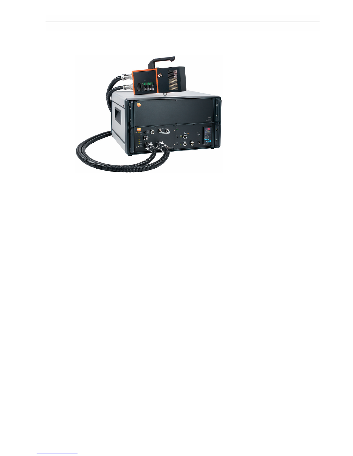
Fig. 4.1 : testo ViPR system consisting of testo CU-2, testo MD19-3E, and testo
ASET15-1
Fig. 4.1 shows a testo ViPR system consisting of testo CU-2 Digital Control Unit, testo MD19-3E
Rotating Disk Diluter, testo ASET15-1 Air Supply / Evaporation Tube. Together with an engine
exhaust condensation particle counter (e.g. TSI 3790 EECPC or GRIMM 5.431) this system
meets PMP requirements and can be controlled via Ethernet.
4.4.2. Functionality
testo CU-2 Digital Control Unit is built in a standard 19" case and therewith can be integrated into
a 19" rack together with other devices like the controlled testo ASET15-1 with integrated testo
MD19-3E.
An embedded computer is built in with Windows Embedded Standard as operating system. This
permits to operate the unit in different modes: Manual control, local software control, remote
computer software control via Ethernet, or control by host computer via AK interface.
Besides the Testo aerosol conditioning system consisting of testo MD19-3E Rotating Disk Diluter
and testo ASET15-1 Air Supply / Evaporation Tube a TSI 3790 EECPC, GRIMM 5.431 or another
CPC particle counter can be controlled via serial port and up to 5 analog signals from other
external sources can be logged.
Data logged by testo CU-2 can be saved on the integrated flash memory, a USB memory stick or
to any network storage Windows Embedded can access via Ethernet.
Page 11
4 System Overview
11
4.5. Control Elements and Connections
4.5.1. Front and Rear View
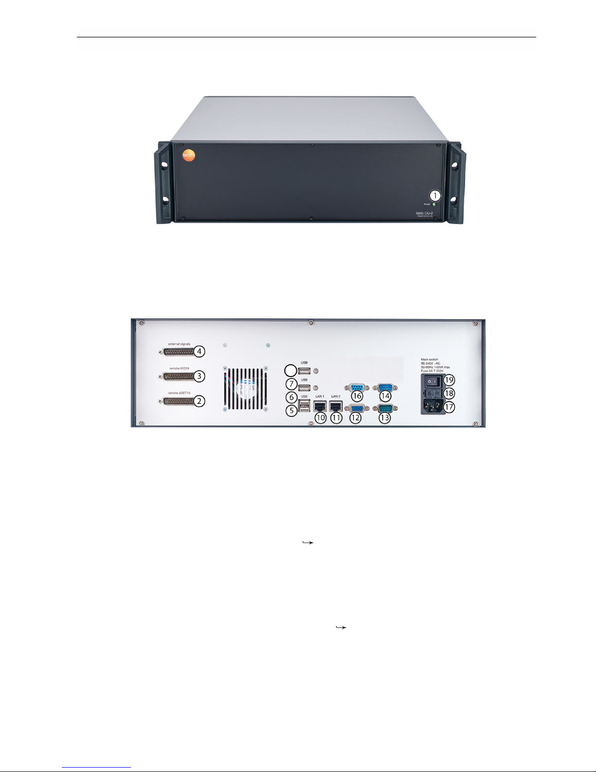
Fig. 4.3: front view of testo CU-2
Fig. 4.3 shows the front of testo CU-2. There are no control elements except the power LED 1)
indicating if the device is switched ON or OFF. All connectors and the mains switch are located at
the rear side which is shown in Fig. 4.4. The testo CU-2 is either completely controlled via
Ethernet or locally by using keyboard, mouse and VGA monitor which can be connected to the
according ports.
Fig. 4.4: rear view of testo CU-2
1 Power LED
2 testo ASET15-1 Air Supply / Evaporation Tube (PND2 + VPR) interface
3 testo MD19-3E Rotating Disk Diluter (PND1) interface
4 male 25 pin D-Sub connector for analog and digital in- and output signals
5 USB connector of embedded computer
6 USB connector of embedded computer
7 USB connector of embedded computer used as default port for GRIMM 5.431 for
PMP R-83 measurements
8 USB connector of embedded computer
9 not used
10 LAN 2 connector of embedded computer; default setting: DHCP
11 LAN 1 connector of embedded computer; default IP adress: 192.168.1.129
12 VGA monitor connector of embedded computer
13 Male serial connector 1 of embedded computer used as default port for EECPC 3790 for
PMP R-83 measurements
14 Male serial 2 connector of embedded computer
15 not used
16 Female serial 3 connector to control testo CU-2 by AK host computer
17 Mains connector
18 Fuse holder; fuse: 250 V, 5.0 A, t
19 Mains switch
Page 12
5 Installation and Setup
12
The properties of the devices connected to testo CU-2 are specified in appendix A.2
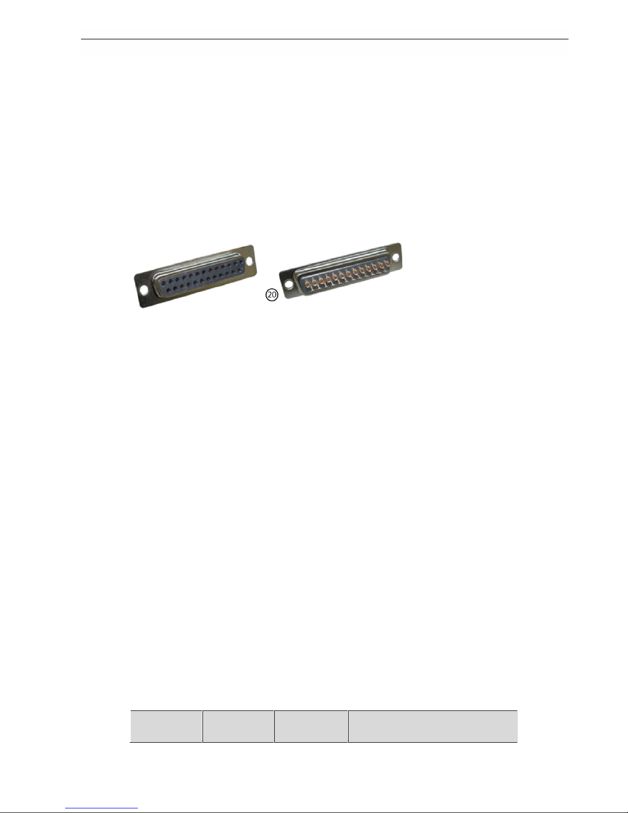
4.5.2. Additional Analog and Digital In- and Output Connector 20)
testo CU-2 is delivered with a female connector 20) which is shown in Fig. 4.5. This connector
can be plugged into the external signals port 4). It is equipped with solder pins which can be used
as contacts for different analog and digital inputs and outputs:
• 5 analog input signals (–10...+10 VDC).
• 3 analog output signals which are configured by the testo NanoMet software
(0...+10 VDC).
• a digital input signal (0 or 5...25 VDC) which can be used to trigger data logging
• 2 digital alarm outputs delivering a 24 VDC signal in case of an error detected by the
testo NanoMet software. These alarm signals are also configured individually by the testo
NanoMet software.
Fig. 4.5: front and rear of external in- and output signals connector 20)
The pin assignment of the external signals port 4) and the specific connector 20) is described in
chapter 8.3.
5 Installation and Setup
Note: Numbers – e.g. 2) = testo ASET15-1 interface – refer to the operating elements illustrated
in chapter 4.5 and appendix A.3.
5.1. Hardware Setup
There are no big efforts to install testo CU-2 and combine it with testo MD19 Rotating Disk Diluter
and testo ASET15-1 Air Supply / Evaporation Tube.
Simply use standard 25 pin D-Sub cables to connect these devices to testo CU-2. The remote
control interface connector of the stand-alone testo MD19-3E is located at the rear side of the
testo MD19-3E laboratory case. If testo MD19-3E is integrated in an testo ASET15-1, the
interface connectors of both components are situated at the rear of the testo ASET15-1 case.
Both interfaces have to be connected to connectors 2) and 3) at the rear side of testo CU-2.
If analog input signals should be recorded or provided by testo CU-2, these external devices
might be connected to the external signals port 4), using a standard 25 pin D-Sub cable with
female connector, or using the external signals connector 20). Two alarm voltage signals can
also be tapped from the external signals port 4) and a trigger signal can be applied to start and
stop data logging. The pin assignment of the external signals port 4) and therewith the
connector 20) is described in chapter 8.3.
Connect the testo CU-2 to your computer network or directly to a host computer using a
crossover network cable, if the system should be remote controlled via Ethernet, use a 9 pin
RS-232 cable to connect it to an AK host computer, or add a VGA monitor, keyboard and mouse
to work directly on the testo CU-2.
The different operation modes are described in chapters 5.3 and 5.4.
5.2. Windows Embedded and Network Setup
5.2.1. Windows Embedded Login
testo CU-2 Digital Control Unit is delivered with Microsoft Windows Embedded installed. There
are two Windows users predefined:
user name
default
password
windows user
rights
remarks
Page 13
5 Installation and Setup
13
Admin Admin no restrictions
only recommended for remote
desktop operation and system setup
e.g. integration in local network
CU-2 CU-2 limited rights
recommended standard user,
automatically logged after system
boot up
For more detailed information or to integrate the testo CU-2 into your network please contact your
network administrator.
When the device is switched on, the embedded computer boots and the testo NanoMet software
is automatically started. The duration of operation system and testo NanoMet software startup is
about 100 seconds. After this time the system is ready for either manual operation of the dilution
system, or testo NanoMet software control, or AK host computer control.
5.2.2. Network Settings
testo CU-2 is equipped with two RJ45 sockets to connect the device to a Ethernet network. By
default the LAN 1 connection has no fix IP address but is set to DHCP while LAN 2 has assigned
the fixed IP address 192.168.1.129. LAN 1 connection using may be used to connect the device
to a network equipped with a DHCP server. LAN 2 is intended to be used for a direct connection
to a Windows PC using a crossover network cable.
As all other Windows settings the properties of both LAN connections can be changed in the
Windows system control panel when logged in as administrator.
The testo CU-2 can be found in the network either by using the IP address or the computer
name. The default computer name consists of the part 'testo-' and the serial number of the
individual device, e.g. 'testo-101999'.
5.3. testo NanoMet Software Startup and Operation Mode Selection
Plug in the power cable to the mains connector 17) and switch on the testo CU-2 unit using the
mains switch 19). Windows Embedded Standard boots and the testo NanoMet software is
automatically started. The system is ready for measuring appr. 100 seconds after switching on
the testo CU-2.
If a monitor is attached or the system is controlled by Windows desktop connection the testo
NanoMet user interface shown in Fig. 5.1 appears on the screen.
Fig. 5.1 : testo NanoMet user shell after system startup
5.3.1. Manual Operation Mode
After startup, the testo NanoMet software runs in the manual operation mode. The software
control menu contains the red 'Enable Software Control' button as shown in Fig. 5.2. Either the
Page 14

5 Installation and Setup
14
user can activate software control or the AK host computer can get control access via Ethernet or
serial port.
Fig. 5.2 : testo NanoMet control menu after software startup
Otherwise it might be helpful to remain in manual operation mode if dilution parameters have to
be determined like dilution factors or the total diluted measuring gas amount.
Neither the testo NanoMet software nor the AK host computer controls testo MD19-3E and testo
ASET15-1, even if they are physically connected to testo CU-2. The devices are locally operated
by the control elements at their front panels according to the instructions in the specific user
manuals. testo NanoMet software and AK host can read and log data provided by testo CU-2.
Data logging by testo NanoMet software is started by pushing the 'start data logging' button. The
AK interface is running in the background. Only AK read 'A' commands are possible. Control and
write commands from AK host are responded with 'state = busy' and the AK system runs in
'manual mode'
5.3.2. Software Control Mode
By clicking the software control button, the operator decides the testo NanoMet software to take
control over the aerosol conditioning system, i.e. testo MD19-3E Rotating Disk Diluter and testo
ASET15-1 Air Supply / Evaporation Tube. The software control button turns to grey and could
now be used to disable software control and return to manual control mode.
In software control mode, the system is operated via testo NanoMet user interface. The testo
NanoMet software has prior access to the data acquisition modules.
The AK interface is still running in the background. Only AK read 'A' commands are possible.
Control and write commands from AK host are responded with 'state = busy' and and the AK
system runs in 'manual mode'.
Manual software control mode is mostly used for system configuration, field measurement, or if
no other computer is available. It is possible to work directly on the embedded computer using
monitor, mouse, and keyboard directly connected to the control unit testo CU-2.
5.3.3. Remote Computer Software Control Mode
The system can be controlled by a remote-desktop connection. This is mostly used for
measurements on test-benches if the user operates in a control room and the devices are
mounted in a test cell. It is also used for system checks and configuration changes via Ethernet
without the need of being personally present.
The user directly works on the testo NanoMet software by using a remote-desktop connection. In
this case the operator has the screen from the embedded computer on his workstation monitor
and works on the embedded computer.
The remote desktop connection can be established using the remote desktop connection
software which is installed by default on Microsoft Windows XP professional or newer.
Appropriate remote desktop protocol (RDP) clients are also available for a number of other
operating systems like Windows 2000, 9x, and NT4, but also Mac OS X, Linux and others.
After startup of the RDP software, the testo CU-2 can be found in the network either using its
network computer name (e.g. 'matter-101999') or its IP address which are described in chapter
5.2.2.
The Windows Embedded Standard log-in window appears which is shown in Fig. 5.3.
Page 15

5 Installation and Setup
15
Fig. 5.3: log-in window
Even if the testo CU-2 system is started by default with the standard user 'Matter' without a
password needed, administrator rights are required for remote desktop operation.
An administrator account is created by default with both user name and password: Administrator
(mind the capital letter at the beginning of the password).
If you try to log-in as 'Administrator' for the first time after system startup, i.e. if the standard user
'Matter' is logged in, the message shown in Fig. 5.4 appears.
Fig. 5.4 : standard user log-out message
Confirm by clicking 'Yes' to log-out 'Matter' and change the user to 'Administrator'. After logging in
the testo NanoMet software is automatically started in the manual operation mode described in
chapter 5.3.1 with the control menu shown in Fig. 5.2.
5.4. AK Host Remote Control Mode
Using testo CU-2, the particle number measurement system can be integrated in a test rig. The
testo CU-2 Digital Control Unit can then be controlled by a host computer connected by serial
RS232 port or Ethernet connection. Communication protocol is AK over TCP/IP or RS232.
Detailed AK protocol specifications can be found in chapter 7.
A second host computer can be connected via Ethernet optionally. Only one of the host
computers can control the connected devices but the second one is able to read data using
AK 'A' commands.
The testo NanoMet software has to be in the Manual Operation Mode which is the default mode
after system start up. Then the AK master computer (Host A) can send remote command 'SREM'
to get priority. The testo NanoMet user interface will then be deactivated (software control mode
not available but data still can be read and recorded) and the second host (Host B) can only
execute 'A' commands. This is illustrated in the flow chart of Fig. 5.5.
Page 16

5 Installation and Setup
16
Fig. 5.5: testo NanoMet operation modes flow chart
The command 'SMAN' ends priority state of the master computer (Host A), operator may then
control the diluters manually, switch to software control and use the testo NanoMet software, or
the other host computer (Host B) can get priority by sending 'SREM'. In this case Host A can only
execute AK 'A' commands until Host B ends its priority by sending 'SMAN'.
Page 17

6 testo NanoMet Operation
17
6 testo NanoMet Operation
The testo NanoMet user shell consists of the testo NanoMet main window, the testo NanoMet
control panel, and the CPC control window.
The testo NanoMet main window contains five tabs to set measurement parameters, to select
operation mode and system state, to display the measured values and to do the data saving
settings.
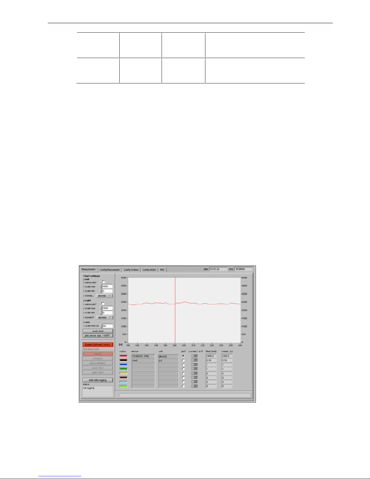
6.1. Main Measurement Tab
The 'Measurement' tab shown in Fig. 6.1 includes the software control menu which was already
described in chapter 5.3.1. It also displays the measured values, contains a chart where the
selected values are plotted, and an error bar at the bottom of the window, where auto-detected
errors are displayed.
Fig. 6.1: measurement tab
For every plotted signal it can be selected if the left or right y-axis should be used. In the chart
settings area, minimum and maximum values of these axes can be set. This is done
automatically if 'y auto scale' is selected. The set minimum and maximum values are useless
then. The 'x scale interval' determines how many seconds should be plotted in the chart. Default
value is 60 seconds, maximum is 1200 seconds = 2 hours.
The system state buttons in the software control menu are active when the system is operated in
the software control mode, as it is shown in Fig. 6.2. The system state is selected using these
buttons. The actual system state is marked by the red button.
6.1.1. Pause State
PAUSE state means that all pumps and heatings of testo MD19-3E and testo ASET15-1 are
switched off.
6.1.2. Standby State
STANDBY state means the system is ready for measurements. Pumps for sample gas and
dilution air are switched on as well as the heaters of primary dilution head and the evaporation
tube. Only the diluter disk is not rotating and therewith the dilution air passes the diluter without
being added by any amount or raw gas.
Page 18

6 testo NanoMet Operation
18
Fig. 6.2: testo NanoMet control menu in software control mode
6.1.3. Measurement state
In the MEASUREMENT state the disk starts to rotate. The system is ready to measure.
6.1.4. Leak Test
UN-ECE R83 reglementations require a system leakage test to be executed prior to each
measurement test cycle. This leakage test is effected by feeding filtered air into the inlet of the
entire particle sampling system. The particle counter shall then report a measured concentration
of less than 0.5 #/cm3.
This test can be performed automatically selecting the LEAK TEST state in the testo NanoMet
control menu. In this state all parameters are set as in the measurement state except that the
primary diluter disk is not rotating.
This means no raw gas is added and therewith the filtered dilution air passes the dilution system
instead of measuring gas. If the detected particle concentration does not recede to zero, either
the secondary dilution air flow is set too low which leads to ambient air sucked through the
excess air outlet port, or some leakage occurs, probably caused by a filter defect, by a failure at
the diluter disk, an untight connection, or by a sensor defect.
The leak test will start when 'start data logging' is clicked if the LEAK TEST state is selected.
After 2 minutes test duration the system returns to the STANDBY state. The data logged during
the leak test are saved in the selected data folder.
6.1.5. Zero Test
A PNC zero test is required once a day for UN-ECE R83 applications. In terms of this test filtered
air has to be feeded to the particle counter PNC. The PNC shall then report a measured
concentration of ≤ 0.2 #/cm3. The PNC shall show an increase in measured concentration to at
least 100 #/cm3 when challenged with ambient air and return to ≤ 0.2 #/cm3 when filtered air is
applied again.
The ZERO TEST state of the testo NanoMet software cannot supply ambient air to the PNC but
filtered air can be provided by the testo ASET15-1 when the primary dilution air supply is turned
off and neither measuring gas nor dilution air passes the evaporation tube and only dilution air
enters and leaves the secondary mixing chamber. If the amount of secondary dilution air exceeds
the inlet flow of the PNC, it can only draw filtered air. Ambient air can be provided by manually
pulling off the tube connector from the testo ASET15-1 measuring gas outlet.
If the PNC signal does not recede to zero during the zero test, either the secondary dilution air
filter or the sensor might be faulty.
The indicated particle concentration values during the zero test are recorded and saved in the
selected data folder during 2 minutes when 'start data logging' is clicked.
The ZERO TEST can also be used to isolate the reason for leakage found in a leak test. If the
signal turns to zero in the zero test but not in the leak test, the leakage will probably be found in
the primary dilution subsystem.
Page 19

6 testo NanoMet Operation
19
6.2. Measurement Configuration
The 'Config Measurement' tab shown in Fig. 6.3 serves to set the measurement parameters. It
will be selected what should be calculated by the software out of the measured particle
concentration values, how data logging will be started and stopped, and where the logged data
should be saved.
Fig. 6.3: measurement configuration tab
6.2.1. UN-ECE R83 Measurement and Test Cycle Definition
If the 'UN-ECE R83 measurement' button is activated, the measurements will follow a test cycle
consisting of up to 5 parts.
Each test of a cycle will be analyzed and particle number will be calculated in #/km according to
UN-ECE R83. The results are saved in the header of the saved file.
The desired test cycle is selected in the 'test cycle' menu. To change one of these predefined
cycles, it first must be selected, then the cycle name has to be entered in the text field right from
the 'test cycle' menu. The cycle part durations are entered in the fields below, and the newly
defined cycle is saved by clicking on the 'OK and save' button.
For the software to calculate the emissions in #/km, the 'cycle data information' window shown in
Fig. 6.4 appears after the data logging is completed. In this window, the amout of exhaust gas
volume and the virtually covered distance of the tested vehicle have to be entered for every cycle
part for the testo NanoMet software to calculate the emitted particle number per kilometer #/km.
The exhaust gas volume usually is the CVS total volume if the whole engine exhaust stream is
fed to and the particle sample was drawn from the CVS.
Page 20

6 testo NanoMet Operation
20
Fig. 6.4 : cycle data information window
6.2.2. General Measurement Settings
On the 'Config Measurement' tab it is also set if data logging will be started by a trigger signal or
manually and stopped manually or after a predetermined cycle time. Furthermore the sample rate
can be set between 2 and 5 Hz, and the signal averaging interval is set. This setting will have a
significant influence on the amount of data generated during the measurements.
By marking the 'include date in timestamp' control the date will also be saved in the first column
of each entry in the data storage file. This option is usually used for long time and overnight
measurements.
In the bottom line of the 'Config Measurement' tab the path can be set where the logged data
should be saved. This can either be locally on the internal memory of the embedded computer,
an added USB storage device, or an accessible folder in the network where the testo CU-2 digital
control unit is implemented.
The default folder for the logged data to be saved by the testo NanoMet software is
'D:\MEASUREMENT DATA' on the internal flash memory of the embedded computer. The
standard user 'CU-2' has no rights to access other folders.
6.3. System Configuration
The system components must be specified in the 'Config System' tab shown in Fig. 6.5. The
round check buttons can be activated independently of each other.
6.3.1. Measurement Instruments
With the round check button, it is set if any testo NanoMet controllable particle detection sensor is
attached and should be used for the measurements, or if just the dilution and conditioning
components testo MD19 -3E Rotating Disk Diluter and testo ASET15-1 Air Supply / Evaporation
Tube are controlled by the testo NanoMet software.
The port where the sensor is attached to the testo CU-2 digital control unit can be set.
Selectable sensors are TSI condensation particle counters CPC 3010, 37xx, engine exhaust
condensation particle counter EECPC 3790, GRIMM 5.431 or the EcoChem PAH monitor
PAS2000. The serial number and the measuring unit can be entered.
Furthermore, a CPC correction factor k can be entered, according UN-ECE R83 regulations. This
factor can be used to compensate a certain CPC signal deviation which possibly has been found
when the sensor has been compared to a reference device.
Page 21

6 testo NanoMet Operation
21
Fig. 6.5: system configuration tab
6.3.2. Dilution Instruments
As secondary dilution unit PND2 only the testo ASET15-1 Air Supply / Evaporation Tube can be
selected or not.
The testo MD19-3E is intended as primary dilution unit PND1. testo MD19-3E supports extended
remote control functions like to control the primary diluter temperature and the raw gas pump by
the testo NanoMet software as well as it is possible to read raw gas temperature and pressure
and several error informations by testo CU-2 Digital Control Unit. The testo NanoMet control
panel is added by these additional functions if testo MD19-3E is selected as primary diluter.
Along with the Rotating Disk Diluter version the rotating disk type has to be selected. The
10 cavities disk serves to realize lower dilution factors while higher dilution factors are achieved
using the 8 cavities disk, as it is described in the testo MD19-3E user manual.
The 'use fr or standard calibration' menu in the system configuration tab shown in Fig. 6.5 allows
to set if measurements should be performed using the attached devices applying their standard
calibrations, or if PMP compliant calibrations according UN-ECE R83 should be applied.
By clicking the 'change' button the calibration factors settings window shown in Fig. 6.6 can be
opened to insert the calibration data out of the documents delivered with the dilution components
to the testo NanoMet software.
As standard, the instruments are calibrated individually. The more extensive and more detailed
PMP calibration is done with the components combined to one system.
For setting up the system according UN-ECE R83, the nominal primary and secondary dilution
factors have to be approximately determined. The best fitting dilution settings out of the
calibration certificate have to be selected and entered into the corresponding fields of the
calibration factors window, together with the PCRF determined in line with these values during
the calibration procedure.
Page 22

6 testo NanoMet Operation
22
Fig. 6.6: calibration factors settings window
To use the standard calibration, simply the two calibration factors determined for both testo
MD19-3E diluter disks must be entered in the specific field. There is no need for testo ASET15-1
calibration figures because in terms of its calibration this device has been adjusted to meet
exactly its nominal dilution factors.
6.3.3. AK Interfaces
An AK host computer may either connect to the testo CU-2 Digital Control Unit via serial
connection or via TCP/IP using one of the two LAN connectors of the device.
If a serial connection should be used, COM4 is set by default. This port is equipped with a female
connector while COM1...COM3 have male connectors. This is done because in this case testo
CU-2 is connected to the AK server as a slave while the other COM ports are used to connect
other slave devices to testo CU-2 Digital Control Unit as master.
Another AK host may connect to testo CU-2, but this one can only execute AK 'A' (read)
commands because only one instance may control the system and therewith execute 'S' (control)
and 'E' (write) commands.
The detail parameters of the connection to the AK host can be set in the 'AK interfaces' section of
the 'Config System' tab.
6.4. Analog Input and Output Signals Configuration
On the 'Config AI/AO' tab shown in Fig. 6.7 the 5 analog inputs can be specified and the
functions of the 4 analog outputs can be selected out of the referring menus. Besides it is set if
one digital output signals should be used for all errors or if the two available signals should
indicate CPC and dilution system errors separately.
Page 23

6 testo NanoMet Operation
23
Fig. 6.7: analog input and output signals configuration tab
6.4.1. Analog In
Using the round check buttons, every analog input and output channel can be activated or
deactivated individually. Active input signals will be recorded in the measurement file during data
logging and will be available for being displayed on the 'Measurement' tab.
For every channel an analog DC voltage range within –10 V DC...+10 V DC can be specified to
equate a certain signal range. Furthermore, the signal can be named and serial number and
signal unit can be entered which will also be saved during data logging.
6.4.2. Analog Out
Fig. 6.8: analog and digital output signal menues
The 4 analog output signals can also be enabled individually. For every voltage output, one
signal can be selected from the menu which is opened by clicking on the signal selection bar.
The output voltage range is 0...+10 V DC. The signal range corresponding to this voltage limits is
set by the operator.
Page 24

6 testo NanoMet Operation
24
6.5. PNC Tab
The informations provided by the attached particle number counter PNC, i.e. TSI condensation
particle counter CPC are shown on the 'PNC tab' shown in Fig. 6.9.
Fig. 6.9: particle number counter PNC tab
If a TSI 37xx or GRIMM 5.431 particle counter is used, these informations are the detected
particle concentration which is also displayed at the CPC front display, the ambient conditions of
the CPC, the temperatures inside the sensor which are relevant for correct operation, the serial
number, any errors, and some operation parameters.
The TSI 3010 model only sends the vacuum information to the control device. This value is
important to ensure sufficient flow through its critical nozzle.
It is also possible to send certain commands to the particle number counter. These are to enable
or disable the automatic functions autofill and water removal for TSI 37xx models and the butanol
fill button for TSI 3010.
6.6. testo NanoMet Control Panel and CPC Window
6.6.1. testo NanoMet Control Panel
The testo NanoMet control panel is shown in Fig. 6.10. It serves to set dilution and conditioning
parameters like primary and secondary dilution factors and temperatures of primary diluter and
evaporation tube of testo ASET15-1. This window also allows to control the testo ASET15-1
pumps and the raw gas pump of testo MD19-3E and it provides information about the hardware
status, i.e. if the set dilution factor and temperatures are reached, if the pump flows are within
their specifications, and if the rotating disk motor works correctly.
Fig. 6.10: testo NanoMet control panel with testo MD19-3E control field
Page 25

7 AK Host Operation
25
The testo NanoMet control panel will be deactivated and its background color will change from
black to grey, if software control is disabled i.e. the system runs in manual or AK host control
mode. It gets active when software control is enabled.
6.6.2. CPC Window
If a 3010 or 37xx condensation particle counter CPC from TSI or GRIMM 5.431 is used as
particle number counter PNC, the actually measured value of this sensor is displayed in the CPC
window shown in Fig. 6.11 as well as the CPC status and a short description of automatically
detected CPC errors.
Fig. 6.11: CPC status window
7 AK Host Operation
7.1. AK Software Integration
The testo NanoMet operation modes are described in chapter 5.3 and 5.4 and illustrated in Fig.
5.5. An AK host computer can simply take control over the system by sending the 'SREM'
command after the software start up if testo NanoMet software control has not been activated
before.
The testo NanoMet software is started and therewith the system including AK module is ready
appr. 100 seconds after the testo CU-2 is switched on.
7.2. AK Interfaces Specifications
7.2.1. Serial Interface
The RS232 V24 9-pin male connector at the back of the unit is used to connect a master
computer with the following pin assignment:
Pin 3 = Txd (transmit)
Pin 2 = Rxd (receive)
Pin 5 = Gnd (ground)
All serial parameters fo the AK communication can be configured in the testo NanoMet software:
parameter
select
able values
default settings
baud rate
1200, 2400, 4800, 9600, 19'200, 38'400
9600
start bit
1 1
data bits
7 or 8
8
stop bits
1 or 2
1
parity
even, odd, none
none
handshake
Xon/Xoff
Xon/Xoff
Page 26

7 AK Host Operation
26
7.2.2. TCP/IP Interface
There are two RJ45 connector at the back of the unit for the TCP/IP communication. Both ports
may be used to connect one or two host computers to the testo CU-2.
There are two parameters necessary for the AK communication:
• IP addresses of the computer. These can be changed when logged in as administrator
on the embedded computer.
Default value for LAN2: 192.168.1.129, LAN1 is set to DHCP by default.
These addresses may have to be changed to connect the testo CU-2 to a network.
The embedded computer can be identified in a network by its network name.
Default name of testo CU-2 is 'MATTER-[Serial number]', e.g.: 'MATTER-101999'
• The AK port addresses can be configured in the testo NanoMet software. Each port must
be a number between 0 and 65535. Default values are 49152 (Host A) and 49153 (Host
B).
Both ports are used at the two IP addresses, respectively LAN ports.
Numbers from 0 up to 49151 should not be used, because they are officially registered
and reserved.
7.3. AK Protocol Specification
7.3.1. AK Command Telegram
protocol: hex: description
1. Byte STX
HEAD
02 start byte
2. Byte DON'T CARE (30)
any byte, configurable in testo
NanoMet software
default = 30 h = '0'
3. Byte FUNCT.CODE1
function code, 4 bytes
4. Byte FUNCT.CODE2
5. Byte FUNCT.CODE3
6. Byte FUNCT.CODE4
7. Byte BLANK
VARIABLE DATA
(length depending
on functional code)
20 blank (space, 20 h)
8. Byte 'K' 4B
K for channel / device with
following number
9. Byte NUMBER
device number,
always = 0, 1 byte
DATA
data depending on functional
code
n. Byte ETX END 03 end byte
7.3.2. AK Response Telegram
protocol:
hex: description
1. Byte
STX
HEAD
02
start byte
2. Byte
DON'T CARE (30)
any byte, configurable in testo
NanoMet software
default = 30 h = '0'
3. Byte
FUNCT.CODE1
function code, 4 bytes
Page 27

7 AK Host Operation
27
4. Byte
FUNCT.CODE2
5. Byte
FUNCT.CODE3
6. Byte
FUNCT.CODE4
7. Byte
BLANK
FIXED DATA
20
blank (space, 20 h)
8. Byte
ERROR STATUS
0 when no error, 1...9,
+1 every error status change
DATA
VARIABLE DATA
(length depending
on functional code)
data depending on functional
code, can also disappear
n. Byte
ETX END 03
end byte
7.3.3. General AK Protocol Description
• Every transfer always starts with 'STX', each 'STX' starts a new transfer
• The 'don't care' byte can take any content, excluding control signs or signs reserved by
AK commands. Default value is 0 (30 hex)
• Every function code always includes 4 bytes. A list of all codes can be found in the
following chapters.
• The function code may not contain blanks.
• If the command message contains no error, the response message contains the echo of
the function code and the error status number (0 to 9).
• The echo will be four question marks (????), if the function code has an error or is
unknown, or the command telegram has not a minimum length of 10 bytes.
• There are three groups of function codes:
S = Control commands
A = Read commands
E = Write commands
(S, A, E stands for the German words: 'Steuerbefehle', 'Abfragen', 'Einstellbefehle')
• The particle measurement system is a measurement device and not a functional engine.
Therefore, the identification respectively the channel number is always K0.
• Error status is '0' for an error free running of the system. The error status number will be
counted up from 1 to 9 with each change in the error status. The error status number will
be zero again after all errors are removed.
• The data set is variable. Each data set will begin with a blank (20 h) . A blank is also used
to separate characters of data. The separation with <CR><LF> will only be done, if the
following complete data will have more than 60 digits.
• The long and variable floating point or the E- format are allowed to display the digits of
numbers in the data set. You can find the used formats for all functional codes in the
following chapters. '+/-' may only be used for negative numbers. Digits without physical
meaning have to be removed.
• Every transfer always stops with 'ETX'
7.3.4. Handling of Certain Conditions
• If transfer of a data value is not possible, e.g. a device in the system is missing or it
cannot send a signal, the data will be replaced by a '#'
• The date is only valid with restrictions, e.g. temperature of CPC is not ready. Then data
will begin with '#'
• If a control or adjusting command is sent while the measuring device is in 'Manual' mode,
resp. not set to 'Remote', then response data set = 'OF' (offline)
• If the system is not able to send a response. The host computer has to realize the
missing response by 'time out'
Page 28

7 AK Host Operation
28
• If the system is occupied by executing a previous function, the new start of a control
command will lead to the response 'BS' (busy) in the data block of the response. The
running function will not be disturbed. Exception: The command was a software reset.
• If the system is operated in manual operation mode, also the command 'remote' will be
responded with 'BS'. In this mode only read commands can be used. All control and write
commands will be responded with 'BS'.
• If the data or parameters transfer is not complete (i.e. not expected format) in the
command telegram of the system, the host computer will get a 'SE' (Syntax Error) in the
data block of the response.
• If the system doesn't work with data or parameters of the command (data error,
parameter error) the host computer will get a 'DF' (Data Failure) in the data block of the
response.
• All setpoints set with write 'E' commands will be saved when testo CU-2 will be shut
down and they will be restored after rebooting and set to standby or measurement mode.
7.4. List of All AK Commands
7.4.1. Control Commands – 'S'
CODE: description:
SREM
REMOTE
– set system to AK host remote control mode
SMAN
MANUAL – disable remote control and set system to manual operation
SRES
RESET
– reset all functions and restart system
SPAU
PAUSE
– set system to pause state
STBY
STAND BY
– set system to stand by state
SMGA
MEASURE
– set system to STAND BY state
SNGA
ZERO TEST
– start automatic PNC zero concentration test
SLEC
LEAK TEST
– start automatic system (VPR+PNC) leak test
SINT
INTEGRATOR
START
– start integration, integral avarage
SINA
INTEGRATOR STOP
– stop integration started with SINT
7.4.2. Write Commands – 'E'
CODE: description:
ENOR
set standard conditions temperature and pressure
ETD1
set PND1 temperature
range: 20...150°C
EVD1
set
PND1 dilution factor
range: 15...300 (10 cav.) or 150...3000 (8 cav.)
EVD2
set PND2 dilution factor
range: 1...11
ETET
set ET temperature
range:
20...400°C
EDST
set PND1 diluter disk type and if secondary dilution PND2 shall be used or
7.4.3. Read Commands – 'A'
CODE: description:
ASTZ
STATUS
– read the current operation mode and system state
ASTF
ERROR STATUS
– read the numbers of all current failures
AKON
read the current diluted and undiluted particle number concentrations
APRF
read current
particle concentration reduction factor PCRF
Page 29

7 AK Host Operation
29
CODE: description:
AIKG
concentration integral average calculated since the command SINT
AIKO
concentration integral average calculated since command SINT or last AIKO
ANGA
read the result of the last ZERO TEST
ALEC
read the
result of the last LEAK TEST
ANOR
read the currently set standard conditions: standard temperature and
ATD1
read PND1 temperature
AVD1
read setpoint and actual value of primary dilution factor DF
PND1
AVD2
read setpoint and actual value of
secondary dilution factor DF
PND2
ATET
read evaporation tube ET temperature
AFD2
read the secondary dilution air supply flow Q
AS
in PND2
7.5. Descripton of All AK Commands
7.5.1. Control Commands – 'S'
SREM REMOTE – set system to AK host remote control mode
command: SREM K0 response: SREM E
E: error status 0...9
SMAN MANUAL – disable remote control and set system to manual operation mode
command: SMAN K0 response: SMAN E
E: error status 0...9
SRES RESET – reset all functions and restart system
system status after reset is MANUAL mode and PAUSE state
command: SRES K0 response: SRES E
E: error status 0...9
SPAU
PAUSE – set system to pause state: resting state after system start or
RESET
PND1 disk stopped, sample gas pump off, dilution air pumps off, PND1 and
ET heatings off
command: SPAU K0 response: SPAU E
E: error status 0...9
STBY STAND BY – set system to stand by state: ready for measurements
PND1 disk stopped, sample gas and dilution air pumps on, PND1 and ET
heating on
command: STBY K0 response: STBY E
E: error status 0...9
Page 30

7 AK Host Operation
30
SMGA MEASURE – change from STAND BY to measurement state
PND1 disk rotates, diluted gas flows to PNC
command: SMGA K0 response: SMGA E
E: error status 0...9
SNGA
ZERO TEST – start automatic PNC zero concentration test, duration: 2 min
during SNGA mode other S and E commands will be responded with 'BS'
(busy)
exceptions: 'SRES', 'STBY' or 'SPAU' will stop running zero test
according the UN-ECE R83 regulation the number concentration should be
< 0.2 #/ccm
the result of this test can be read with the command ANGA
command: SNGA K0 response: SNGA E
E: error status 0...9
SLEC
LEAK TEST – start automatic system (VPR+PNC) leak test, duration: 2 min
during SNGA mode other S and E commands will be responded with 'BS'
(busy)
exceptions: 'SRES', 'STBY' or 'SPAU' will stop the running leak test
according the UN-ECE R83 regulation the number concentration should be
< 0.5 #/ccm
the result of this test can be read with the command ALEC
command: SLEC K0 response: SLEC E
E: error status 0...9
SINT
INTEGRATOR START – start integration, integral avarage
integration of values runs until stopped with SINA or restarted with SINT
again
the avarage values can be read with AIKG or AIKO
command: SINT K0 response: SINT E
E: error status 0...9
SINA INTEGRATOR STOP – stop integration started with SINT
command: SINA K0 response: SINA E
E: error status 0...9
7.5.2. Write Commands – 'E'
ENOR
set standard conditions temperature and pressure
(system default: 273.15 K, 1013.25 mbar)
command:
ENOR K0 TTT
PPP
response: ENOR E
E: error status 0...9
TTT: absolute temperature [K] format: floating
point example: '273.15'
PPP: pressure [mbar] format: floating point
example: '1013.25'
Page 31

7 AK Host Operation
31
ETD1
set PND1 temperature the range: 20...150°C
setpoints out of range are rounded to the next lowest respectively highest
possible temperature
command: ETD1 K0 TTT response: ETD1 E
E: error status 0...9
TTT: temperature [°C] range: 20...150°C ECE
R83: 150°C
format: floating point example: '150.0'
EVD1
set PND1 dilution factor range: 15...300 (10 cav.) or 150...3000 (8 cav.)
range: 15...300 for 10 cavities disk or 150...3000 for 8 cavities disk (nominal
values)
setpoints out of range are rounded to the next lowest respectively highest
possible dilution factor
command: EVD1 K0 DDD response: EVD1 E
E: error status 0...9
DDD: dilution factor DF PND1 [ - ] range:
15...300 or 150...3000
format: floating point example: '20.0'
EVD2
set PND2 dilution factor range: 1...11
setpoints out of range are rounded to the next lowest respectively highest
possible temperature
command: EVD2 K0 DDD response: EVD2 E
E: error status 0...9
DDD: dilution factor DF PND2 [ - ] range:
1...11
format: floating point example: '10.0'
ETET set evap. tube ET temperature range: 20...400°C
command: ETET K0 TTT response: ETET E
E: error status 0...9
TTT: temperature [°C] range: 20...400°C ECE
R83: 300...400°C
format: floating point example: '300.0'
EDST
set PND1 diluter disk type and if secondary dilution PND2 shall be used or
not
choose 8 or 10 cavities disk. The disk selection but not the PND2 setting will
be stored and used after reset or system restart. If PND2 is disabled, air
supply pump is switched off and DF
PND2
=
1
command: EDST K0 CC D response: EDST E
E: error status 0...9
CC: used rotating disc format: integer,
2 digits '10' for 10 cavities or '08' for 8 cavities
disk
D: '0' for PND2/pump off '1' for PND2/pump
on
Page 32

7 AK Host Operation
32
7.5.3. Read Commands – 'A'
ASTZ
STATUS – read the current operation mode and system state
three modes inform if the system is manually or remote controlled by current
or another host
if system is remote operated by current host, system state is indicated
command:
ASTZ K0
response:
ASTZ E OOOO SSSS
E: error status 0...9
OOOO: operation mode:
'SREM': remote operation, current host
'SMAN': manual operation
only read commands possible
'SRBS': remote busy another host is in
remote mode (SREM)
SSSS: system state:
'SPAU' pause state
'STBY' standby state
'SMGA' measurement state
'SNGA' zeroing state
'SLEC' leak test mode
ASTF ERROR STATUS – read the numbers of all current failures
command:
ASTF K0
response:
ASTF E a b c d ...
E: error status 0...9
a, b, c, d ... sequence of the numbers of
current system errors which are listed in
chapter ??. example: '11 13 20' means:
– ET temperature wrong
– CPC not ready
– CPC liquid level too low
AKON
read the current diluted and undiluted particle number concentration:
concentration is corrected to the currently set standard conditions (ENOR)
command:
AKON K0
response:
AKON E CCC RRR FFF
E: error status 0...9
CCC: particle concentration corrected to std.
cond. [#/ccm]
E-format: example: '3.26E3' = 3'260 #/ccm
response is not affected by stopped disk
rotation
RRR: concentration CCC multiplied by PCRF
E-format: example: '3.26E5' = 326'000 #/ccm
if disk rotation is stopped, response will be
'NaN'
FFF: particle concentration reduction factor
PCRF format: floating point example: '100.0'
if disk rotation is stopped, response will be 'Inf'
APRF read current particle concentration reduction factor PCRF
command:
APRF K0
response:
APRF E FFF
E: error status 0...9
FFF: particle concentratio reduction factor
PCRF format: floating point example: '100.0'
if disk rotation is stopped, response will be 'Inf'
Page 33

7 AK Host Operatio
n
33
AIKG concentration integral average calculated since the command SINT
command:
AIKG K0
response:
AIKG E CCC RRR FFF
E: error status 0...9
CCC: particle concentration corrected to std.
cond. [#/ccm]
E-format: example: '3.26E3' = 3'260 #/ccm
response is not affected by stopped disk
rotation
RRR: concentration CCC multiplied by PCRF
E-format: example: '3.26E5' = 326'000 #/ccm
if disk rotation is stopped, response will be 'NaN'
FFF: particle concentration reduction factor
PCRF format: floating point example: '100.0'
if disk rotation is stopped, response will be 'Inf'
AIKO concentration integral average calculated since command SINT or last AIKO
command:
AIKO K0
response:
AIKO E CCC RRR FFF
E: error status 0...9
CCC: particle concentration corrected to std.
cond. [#/ccm]
E-format: example: '3.26E3' = 3'260 #/ccm
response is not affected by stopped disk
rotation
RRR: concentration CCC multiplied by PCRF
E-format: example: '3.26E5' = 326'000 #/ccm
if disk rotation is stopped, response will be 'NaN'
FFF: particle concentration reduction factor
PCRF format: floating point example: '100.0'
if disk rotation is stopped, response will be 'Inf'
ANGA
read the result of the last ZERO TEST (started by SNGA command before)
if no zero test has been done since start-up of the system, response is 'NaN'
according UN-ECE R83 the number concentration must be < 0.2 #/ccm
command: ANGA K0 response: ANGA E CCC MMM
E: error status 0...9
CCC: corrected particle concentration [#/ccm]
E-format: example: '0.05E0' = 0.05 #/ccm
MMM: duration in minutes since zero test has
been done
format: integer example '125' = 125 min
ALEC
read the result of the last LEAK TEST (started by SLEC command before)
if no leak test has been done since start-up of the system, response is 'NaN'
according UN-ECE R83 the number concentration must be < 0.5 #/ccm
command:
ALEC K0
response:
ALEC E CCC MMM
E: error status 0...9
CCC: corrected particle concentration [#/ccm]
E-format: example: '0.08E0' = 0.08 #/ccm
MMM: duration in minutes since leak test has
been done
format: integer example '125' = 125 min
Page 34

7 AK Host Operation
34
ANOR
read the currently set standard conditions: standard temperature and
pressure
command:
ANOR K0
response:
ANOR E
TTT PPP
E: error status 0...9
TTT: temperature [K]
format: floating point example: '273.15'
PPP: pressure [mbar]
format: floating point example: '1013.25'
ATD1 reads PND1 temperature
command:
ATD1 K0
response:
ATD1 E TTT
E: error status 0...9
TTT: temperature [°C] for ECE R83: 150°C
format: floating point example: '150.8'
AVD1
read setpoint and actual value of primary dilution factor DF
PND1
if PND1 rotating disk is stopped and therefore DF
PND1
is infinite, response is
'Inf'
command:
AVD1 K0
response:
AVD1 E DDD RRR
E: error status 0...9
DDD: DF
PND1
primary dilution factor setpoint
15...300 or 150...3000, depenting on used disk
format: floating point example: '20.0'
RRR: DF
PND1
primary dilution factor actual
value
format: floating point example: '20.2'
AVD2 read setpoint and actual value of secondary dilution factor DF
PND2
command:
AVD2 K0
response:
AVD2 E DDD RRR
E: error status 0...9
DDD: DF
PND2
setpoint range: 1...11
format: floating point example: '10.0'
RRR: actual DF
PND2
format: floating point example: '10.05'
ATET read evaporation tube ET temperature
command:
ATET K0
response:
ATET E TTT
E: error status 0...9
TTT: temperature [°C] range: 20...400°C ECE
R83: 300...400°C
format: floating point example: '300.5'
AFD2 read the secondary dilution air supply flow QAS in PND2
command:
AFD2 K0
response:
AFD2 E FFF
E: error status 0...9
FFF: flow in lN/min range: 0...15.0 lN/min
format: floating point example: '3.0'
7.5.4. AK Errors List
There are a number of errors which can be detected by the system and read out using the 'ASTF'
command. These error codes are listed below:
Page 35

8 Electrical Connections
35
# error notation description
1 Status PND1 not ready
2 PND1 temperature error
3 Dilution error failure in dilution factor
4 Motor error Rotating disk is blocked
5 Pump error raw gas pump not running
6 Dilution air flow PND1 failure
10 Dilution air flow PND2 failure flow failure or flow too low
11 Temperature ET wrong
Temperature of the evaporation tube differs 10°C
or more from setpoint
12
DF PND2 failure deviation
13 CPC status not ready
14 Saturator temp out of range
15 Condenser temp out of range
16 Optics temp out of range
17 Inlet flow rate out of range
Orifice pressure is < 10 or > 90 kPa. Apply
sufficient external vacuum.
18 Aerosol flow rate out of range
19 Laser power low
20 Liquid level low
21 Concentration out of range value detected by CPC > 1.0E4 #/ccm
22 Multiple Error at CPC
23 No CPC communication
CPC is not connected, switched off or cable
8 Electrical Connections
8.1. Mains Supply
Connect the power cord plug to a grounded power socket. The IEC mains connector 17) on the
rear side of the testo CU-2 case includes the mains switch 19) and the fuse holder 18). The one
phase power cord delivered with the instrument is equipped with a country-specific plug and
protective earth.
Mains supply voltage: 90 ... 240 VAC, 50/60 Hz, max. 140 VA
Fuse type: slow switching fuse 250 V, 5 A, t, 5 x 20 mm
Page 36

8 Electrical Connections
36
Warning
In case of a blown fuse, replace it only with the specified type of fuse. If the fuse
is repeatedly blown, the unit must be sent to the manufacturer or to an
instructed service station for checking and repair.
Electric Shock
Make sure that the protecting ground pin of the country specific plug is correctly
connected to the protecting ground contact of your socket. If the plug is
replaced, ensure the yellow/green ground wire of the cable is properly
connected to the new ground pin or the case is otherwise connected to
protective earth which is usually indicated by the sign.
8.2. Dilution/Conditioning Devices
The testo ASET15-1 interface 2) and testo MD19-3E interface 3) may exclusively be used to
connect these devices to the testo CU-2 digital control unit. The pin assignment of these
interfaces is adapted to the specific analog and digital input and output signals of the testo MD193E Rotating Disk Diluter and testo ASET15-1 Air Supply / Evaporation Tube.
8.3. Analog/Digital Interface
The pin assignment of the external analog and digital in- and output signals interface 4) and
connector 20) is shown in Fig. 8.1.
Fig. 8.1: external in- and output signals connector 20)
The analog and digital inputs and outputs have the following properties and requirements:
• Digital trigger input: high level: 5...25 VDC low level: max. 1 VDC
pull up current: 0.5 mA / load resistance R
in
=
10...50 kΩ
• Digital outputs: high level: 24.0 +/- 0.2 VDC low level: < 0.5 VDC,
maximum load is 30 mA
The analog DC voltage signals are as follows:
• Analog inputs: signal range –10...+10 VDC input impedance R
in
=
20.0 MΩ
• Analog outputs: signal range 0...+10 VDC 12 bit signal
output impedance R
out
=
0.5 Ω.
Dsub
pin
signal description
polarity
analog
/ digital
input /
output
signal range
1 analog input 0 + A I –10...+10 VDC
2 analog input 1 + A I –10...+10 VDC
3 analog input 2 + A I –10...+10 VDC
4 analog input 3 + A I –10...+10 VDC
5 analog input 4 + A I –10...+10 VDC
6
PNC error (if multiple DO ports error is
+ D O +24 VDC
7 dilution system error (or single port error) + D O +24 VDC
8 digital input: trigger signal + D I 5...25 VDC
10 analog output 0 + A O 0...+10 VDC
11 analog output 1 + A O 0...+10 VDC
Page 37

8 Electrical Connections
37
Dsub
pin
signal description
pola-
rity
analog
/ digital
input /
output
signal range
12 analog output 2 + A O 0...+10 VDC
13 analog output 3 + A O 0...+10 VDC
14 analog input 0 – A I –10...+10 VDC
15 analog input 1 – A I –10...+10 VDC
16 analog input 2 – A I –10...+10 VDC
17 analog input 3 – A I –10...+10 VDC
18 analog input 4 – A I –10...+10 VDC
20 ground for digital in- and outputs – D 0 VDC
25 ground for analog outputs – A O 0 VDC
8.4. Standard Embedded Computer Ports
The USB ports 5)...8), the LAN connectors 10) and 11), the VGA monitor connector 12), and the
serial ports 13) 14) and16) are standard peripherals connections of the embedded computer.
However some of them are used to connect some measuring components to the system.
A TSI CPC 3010 or 37xx or EECPC 3790 or a PAH monitor PAS2000 can be attached to serial
port 1 13).
A GRIMM CPC 5.431 should be connected to USB-Port 7).
AK host computer(s) can be connected via Ethernet on the LAN connectors 10) and 11) or via
COM port 4 16).
USB storage devices may be plugged into the USB ports 5)...6) to save recorded data directly.
All other standard computer ports can be used to attach peripherals like mouse, keyboard,
monitor, and printer.
Page 38

9 Maintenance and Calibration
38
9 Maintenance and Calibration
9.1. Storage, Acclimatization
Fast ambient temperature changes may result in condensed water on and inside the instrument.
This may cause serious damage of electronic parts, e.g. the controller or safety devices.
• Do not store the instrument outdoor, the storage environment must be clean and dry.
• After long time storage or transport with cold ambient conditions or thermal fluctuation,
the instrument requires to adapt slowly to the local ambient conditions before starting up.
• If condensed water has formed, wait at least 12 hours before installation and starting up.
• Avoid mechanical damage and agitation.
• Storage temperature range: -10°C to +60°C.
9.2. Operation Environment Requirements
Caution
Read this section carefully before setting up testo CU-2 Digital Control Unit.
Testo SE & Co. KGaA is not liable if the instrument is damaged, caused by the
operation environment not meeting the requirements.
Caution
The testo CU-2 Digital Control Unit is designed to be installed in a laboratory, test
stand or a temporary test set-up. The instrument is not intended to be used
outdoor or in a dusty or wet environment.
IP protection
degree
IP 20. testo CU-2 is protected against accidental contact to
dangerous parts of the instrument. It is not protected against intrusion
of sand, dust or water. Avoid operation in dusty or wet environment
for safe and reliable operation.
operating temperature range
The operating ambient temperature range is +10°C to +40°C if free air
circulation around the device is ensured.
humidity range The ambient relative humidity range (RH) is 0% to 90%
shocks and
vibrations
Avoid operation under any kind of shock or vibration.
Page 39

10 Appendix
39
10 Appendix
10.1. Extent of Delivery
testo CU-2 delivery consists of the following items:
item # description
1 testo CU-2 Digital Control Unit
2 testo CU-2 accessories box, containing:
3 user manual to testo CU-2 Digital Control Unit
4 IEC power cord for Switzerland
or for Germany, France, Italy, Korea, etc.
or for USA, Canada, Japan, etc.
or for United Kingdom, etc.
5 1 crossover Ethernet cable
6
2 D-Sub cables for connecting testo MD19-3E and testo ASET15-1 to testo
CU-2
7 1 external signals connector 20)
10.2. Specification, Technical Data
compatible
measurement
devices
•
Testo testo MD19-3E Rotating Disk Diluter
•
Testo testo ASET15-1 Air Supply / Evaporation Tube
•
GRIMM 5.431; TSI CPC 3010 or 37xx or EECPC 3790
or Eco Chem PAS2000 PAH monitor
•
sensors providing analog DC voltage signals –10...+10 VDC
operation
modes
•
manual control: only data acquisition via testo CU-2
•
local software control: mouse, keyboard and monitor attached to testo
CU-2
•
remote software control via Windows remote desktop connection
•
AK control via Ethernet or serial communication
peripherals
standard computer peripherals using serial ports, USB, PS/2 sockets,
VGA monitor connector
power supply 90...240 VAC, 50/60 Hz, max. 140 VA
assembly
3U-19" case for rack mounting with handles
dimensions (w
∙ h ∙
d): 485
∙
146
∙
470 mm
weight ca. 6.5 kg
operating
conditions
T
amb
: 10 ... 40 °C
0...90% relative humidity
Conformity testo CU-2 Digital Control Unit is not CE-conform
Page 40

10 Appendix
40
10.3. Designation of All testo CU-2 Digital Control Unit Operating Elements
1 Power LED
2 testo ASET15-1 Air Supply / Evaporation Tube (PND2 + VPR) interface
3 testo MD19-3E Rotating Disk Diluter (PND1) interface
4 male 25 pin D-Sub connector for analog and digital in- and output signals
5 USB connector of embedded computer
6 USB connector of embedded computer
7 USB connector of embedded computer used as default port for GRIMM 5.431 for
PMP R-83 measurements
8 USB connector of embedded computer
9 not used
10 LAN 2 connector of embedded computer; default setting: DHCP
11 LAN 1 connector of embedded computer; default IP adress: 192.168.1.129
12 VGA monitor connector of embedded computer
13 Male serial connector 1 of embedded computer used as default port for EECPC 3790 for
PMP R-83 measurements
14 Male serial 2 connector of embedded computer
15 not used
16 Female serial 3 connector to control testo CU-2 by AK host computer
17 Mains connector
18 Fuse holder; fuse: 250 V, 5.0 A, t
19 Mains switch
Fig. 4.3 : front view of testo CU-2
Fig. 4.4: rear view of testo CU-2
Fig. 4.5: external signals connector
Page 41

10 Appendix
41
Page 42

Testo SE & Co. KGaA
Testo-Strasse 1
79853 Lenzkirch Germany
phone: +49 7653 681 5062
fax: +49 7653 681 95062
e-mail: sales-nanoparticle@testo.de
 Loading...