

Page 1
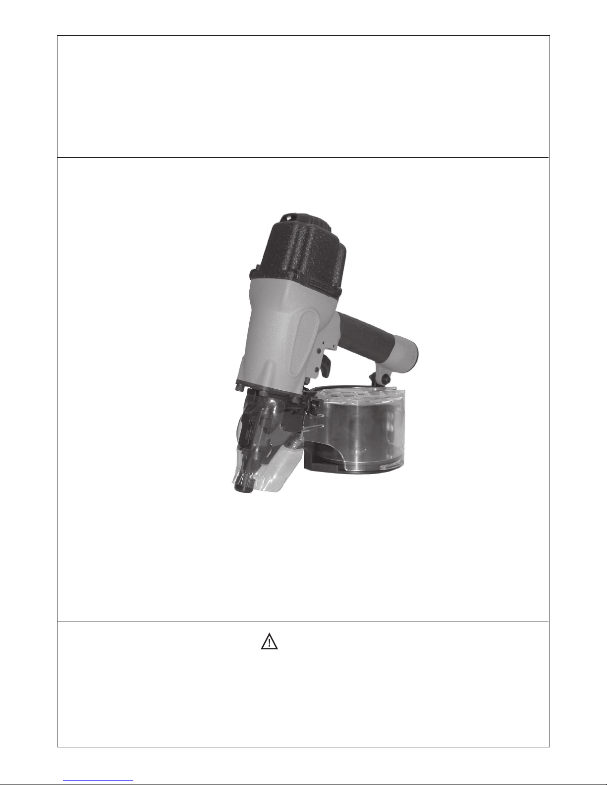
Instruction Manual
COIL NAILER
WARNING
BEFORE OPERATING THIS TOOL, ALL OPERATORS SHOULD STUDY THIS MANUAL, TO UNDERSTAND
AND FOLLOW THE SAFETY WARNINGS AND INSTRUCTIONS. IF YOU HAVE ANY QUESTIONS,
CONTACT WITH OUR REPRESENTATIVES OR DISTRIBUTOR.
CN45R4, CN2150C, CN2565S1, CN3383C1, CN3390C1
CN2360P, CN2970P, CN2970M, CN3383P, CN3390P
Page 2
CONTENTS
2
PAGE
TOOL SPECIFICATIONS
NAIL SPECIFICATIONS
EXTERNAL TOOL PARTS
SAFETY INSTRUCTIONS
LUBRICATION AND MAINTENANCE
ACTUATING TOOL
OPERATING THE TOOL
TROUBLESHOOTING GUIDE
3-4
3-4
3-4
4-6
7-8
7
8-10
11
Page 3
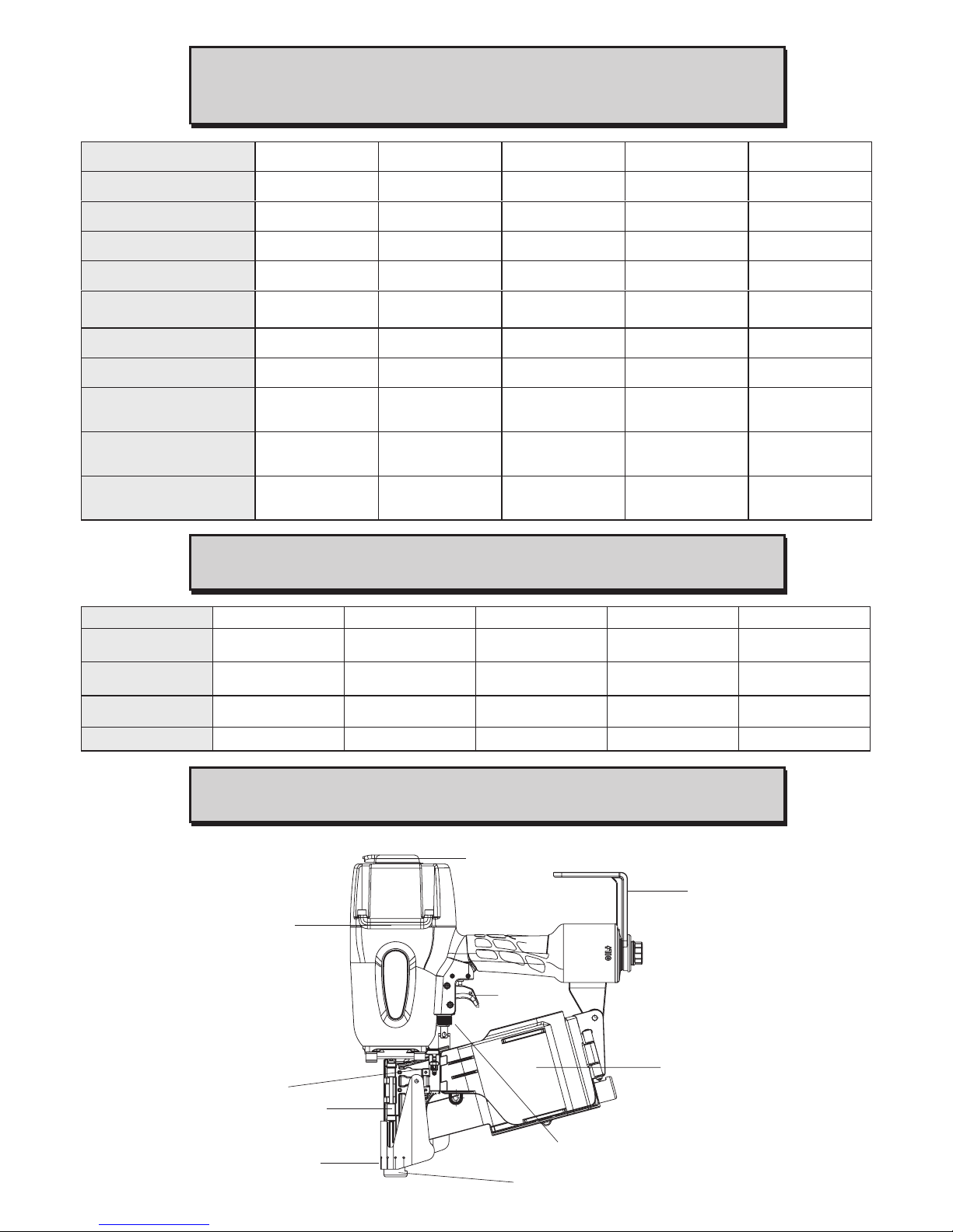
CONSTRUCTION COIL NAILER
TOOL SPECIFICATIONS
NAIL SPECIFICATIONS
EXTERNAL TOOL PARTS
3
360° EXHAUST
DOOR
LATCH
GUIDE
COVER
DEBRIS SHIELD
NOSE
DEPTH ADJUSTING
NO-MAR PAD
TRIGGER
BELT
HOOK
CANISTER
ASSEMBLY
Model No.
Height
Width
Length
Weight
Operating Pressure
Loading Capacity
Accessories
A-weighted single-event
sound pressure level
--- LpA, 1s, d
A-weighted single-event
sound power level
--- LWA, 1s, d
Weighted root mean
square acceleration
--- m/s
2
CN45R4 CN2150C CN2565S1 CN3383C1 CN3390C1
11.1” (281mm) 10.9” (278mm) 12.6” (320mm) 13.4” (340mm) 13.9” (354mm)
4.4” (112mm) 4.3” (110mm) 5.1” (130mm) 5.4” (136mm) 5.4” (136mm)
9.5” (241mm) 9.5” (240mm) 10.7” (273mm) 13.3” (339mm) 13.3” (339mm)
4.86 lbs (2.43kgs) 3.65 lbs (1.66kgs) 4.8 lbs (2.2kgs) 7.45 lbs (3.38kgs) 7.58 lbs (3.44kgs)
70 ~ 120 psi
(4.9 ~ 8.3 bar)
70 ~ 110 psi
(4.9 ~ 7.6 bar)
70 ~ 120 psi
(4.9 ~ 8.3 bar)
70 ~ 120 psi
(4.9 ~ 8.3 bar)
70 ~ 120 psi
(4.9 ~ 8.3 bar)
120 nails 200/400 nails 250/400 nails 200/300 nails 200/300 nails
Belt Hook Belt Hook Belt Hook Belt Hook Belt Hook
93 dBA 92 dBA 90 dBA 95 dBA 95 dBA
101 dBA 101 dBA 101 dBA 103 dBA 103 dBA
3.1 m/s
2
2.8 m/s
2
3.0 m/s
2
3.7 m/s
2
3.7 m/s
2
Model No. CN45R4 CN2150C CN2565S1 CN3383C CN3390C1
Nail Length
3/4”-1 3/4”
(19-45mm)
1”-2”
(25-50mm)
1 1/4”-2 1/2”
(32-65mm)
2”-3 1/4”
(50-83mm)
2”-3 1/2”
(50-90mm)
Shank Diameter
.120”
(3.05mm)
.063”-.083”
(1.6-2.1mm)
.092”-.099”
(2.3-2.5mm)
.099”-.131”
(2.5-3.3mm)
.099”-.131”
(2.5-3.3mm)
Shank Type
Smooth, Ring,
Screw
Smooth, Ring,
Screw
Smooth, Ring,
Screw
Smooth, Ring,
Screw
Smooth, Ring,
Screw
Collated Wire Wire/Plastic Wire/Plastic Wire Wire
Page 4
4
P 3 8 33N CC3 83 3NCP093 3NC C09 3 3 NC
2”-3 1/2”
(50-90mm)
2”-3 1/2” (50-90mm) 2”-3 1/4” (50-83mm)
2”-3 1/4”
(50-83mm)
.099”-.131”
(2.5-3.3mm)
.099”-.131”
(2.5-3.3mm)
.099”-.131” (2.5-3.3mm)
.099”-.131”
(2.5-3.3mm)
Smooth, Ring,
Screw
Smooth, Ring, Screw Smooth, Ring, Screw
Smooth, Ring,
Screw
Model No.
CN2360P CN2970P CN2970M CN3383P CN3390P
Nail Length
1”-2 1/4”
(25-60mm)
1 3/4”-2 3/4”
(45-70mm)
1 3/4”-2 3/4”
(45-70mm)
2”-3 1/4”
(50-83mm)
2”-3 1/2”
(50-90mm)
Shank Diameter
.083”-.092”
(2.1-2.3mm)
.099”-.113”
(2.5-2.9mm)
.099”-.113”
(2.5-2.9mm)
.099”-.131”
(2.5-3.3mm)
.099”-.131”
(2.5-3.3mm)
Shank Type
Smooth, Ring,
Screw
Smooth, Ring,
Screw
Smooth, Ring,
Screw
Smooth, Ring,
Screw
Smooth, Ring,
Screw
Collated Wire Wire Wire Wire Wire
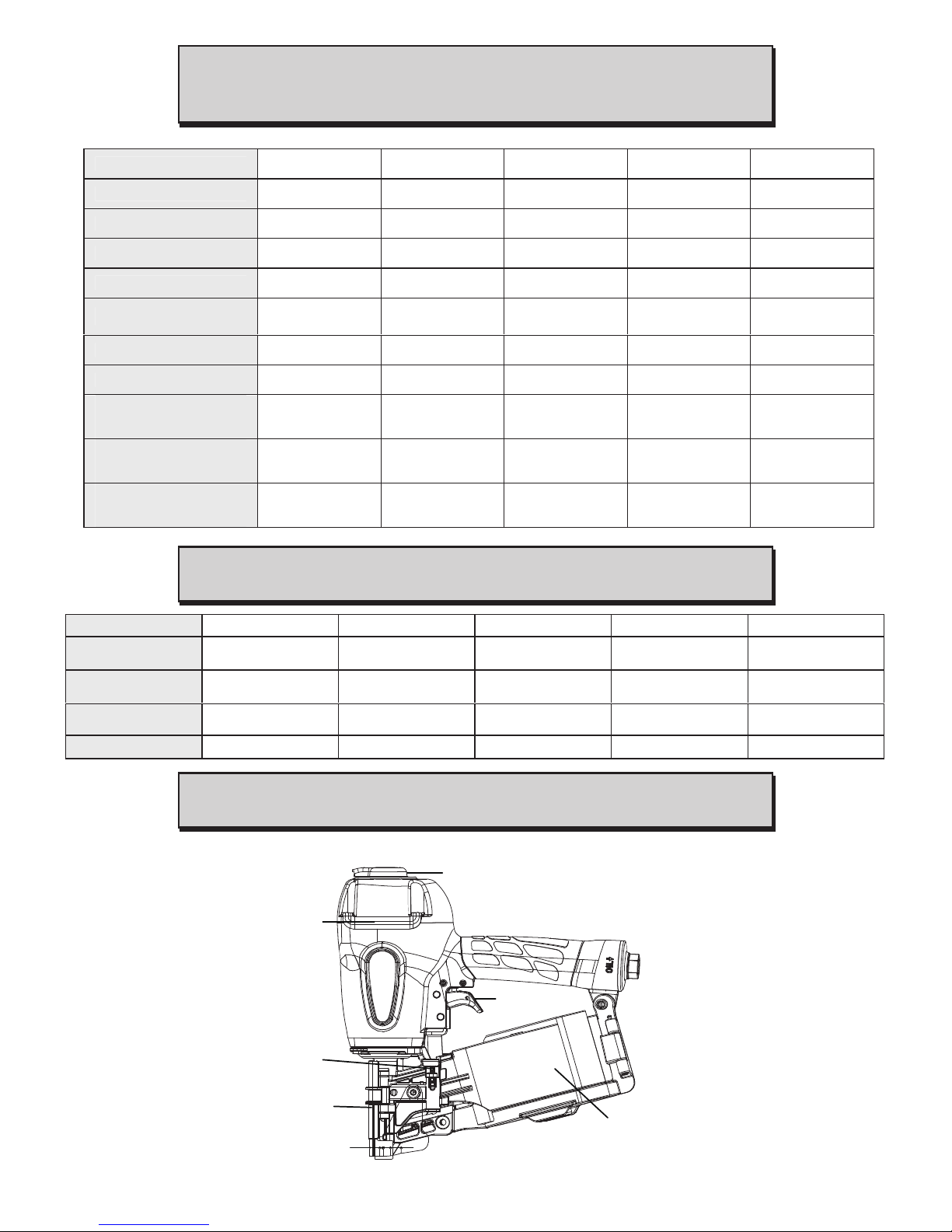
EXHAUST DEFLECTOR
TRIGGER
CANISTER
ASSEMBLY
DOOR
LATCH
NOSE
GUIDE
COVER
DEBRIS
SHIELD
INDUSTRIAL COIL NAILER
TOOL SPECIFICATIONS
NAIL SPECIFICATIONS
EXTERNAL TOOL PARTS
Model No. CN2360P CN2970P CN2970M CN3383P CN3390P
Height 11.9” (301mm) 13” (330mm) 12.1” (308mm) 13.4” (340mm) 13.9” (354mm)
Width 5.4” (136mm) 5” (128mm) 5” (128mm) 5.4” (136mm) 5.4” (136mm)
Length 11.1” (281mm) 12” (306mm) 12.1” (308mm) 13.3” (339mm) 13.3” (339mm)
Weight 5.84 lbs (2.65kgs) 7.7 lbs (3.5kgs) 7.7 lbs (3.5kgs) 6.9 lbs (3.13kgs) 7.32 lbs (3.34kgs)
Operating Pressure
70 ~ 120 psi
(4.9 ~ 8.3 bar)
70 ~ 120 psi
(4.9 ~ 8.3 bar)
70 ~ 120 psi
(4.9 ~ 8.3 bar)
70 ~ 120 psi
(4.9 ~ 8.3 bar)
70 ~ 120 psi
(4.9 ~ 8.3 bar)
Loading Capacity 300/350 nails 225/300 nails 225/300 nails 200/300 nails 200/300 nails
Accessories - - - - -
A-weighted single-event
sound pressure level
--- LpA, 1s, d
91 dBA 95 dBA 95 dBA 95 dBA
A-weighted single-event
sound power level
--- LWA, 1s, d
102 dBA 104 dBA 103 dBA 103 dBA
Weighted root mean
square acceleration
--- m/s
2
2.3 m/s
2
3.1 m/s
2
95 dBA
104 dBA
3.1 m/s
2
3.7 m/s
2
3.7 m/s
2
Page 5

5
SAFETY INSTRUCTIONS
WARNING: Read this manual and understand all instructions before operating the tool.
If you have any questions, please contact with our authorized representatives.
OX
CO
2
The operator and all persons in the general area should wear
safety glasses to guard against flying fasteners and debris,
which could cause severe eye injury. Safety glasses are per
requirements of the Regulatory Authority. Always wear hearing
protection and hard hat.
Never use oxygen, carbon dioxide or any other bottled gas as
a power source for this tool Danger of explosion and/or
serious personal injury may result.
Use only clean, dry regulated compressed air at recommended
pressure
Tools shall not be connected to a compressor which
potentially exceeds 175 psi or 12 bar.
Air hose rated for a maximum operating pressure of 150 psi
(10.3 bar) or 150% of the maximum system pressure, whichever,
is higher.
Disconnect tool from air supply and remove fasteners from
magazine before doing tool maintenance, clearing a jammed
fastener, leaving work area, moving tool to another location, or
handing the tool to another person.
120 Psi
8.3 bar
70 Psi
4.9 bar
Page 6

6
Coupling must be used which removed all pressure from the tool
when the coupling joint is disconnected.
Never use tool that is leaking air, has damaged or missing parts.
Never point the tools at co-workers or yourself at any time .
Never carry the tool from place to place holding the trigger.
Do not alter or modify this tool from the original design or
function without approval from us or authorized representatives.
Do not remove spring from contact trip, inadvertent actuation
could occur.
Always maintain proper footing and place yourself in a firmly
balance position when using or handling the tool.
Do not drive fasteners on top of other fasteners, the fasteners
can ricochet and hurt someone.
Page 7

7
Never use the body of the tool or top cap as a hammer, always
use the tool for its intended use. Do not discharge fasteners into
concrete, stone, or any material too hard for the fastener to
penetrate.
Do not drive fasteners close to the edge of the work surface.
The workpiece maysplit causing the fastener to ricochet, fly
free or hit someone.
Keep hands and body away from the discharge area of the tool.
Keep face and body away from back of the tool cap when
working in restricted areas. Sudden recoil can result in hard
impact to the body.
Never use tool in the presence of flammable dust, gases or
fumes. The tool may produce a spark that could ignite gases
causing a fire and cause the tool to explode.
Be aware of material thickness when using the nailer.
Page 8

LUBRICATION AND MAINTENANCE
Use Pneumatic tool oil or a non-detergent oil. Do not use
detergent oil or additives as they will damage o-rings and rubber
parts.
Use a filter and regulator when possible
Add pneumatic oil into the air inlet twice daily. (Depending on
frequency of tool use)
Wipe tool clean daily and inspect for wear. Use solvents only if
necessary - Do Not Soak. (Solvents may damage o-rings and
other tool parts)
Drain compressor tanks and hoses daily
Clean magazine, pusher, and contact trip mechanism
periodically.
All screws, nuts and fasteners should be kept tight and
undamaged. Loose screws result in unsafe operation and parts
breakage.
8
Bump Fire Trigger (Black Color)
1. With your finger pulling the trigger, press the safety all the way down
on the surface of the material the fastener is being driven into.
2. This will result in a fastener being driven into the material.
3. To fire another round raise the safety completely off the material and
repeat the above steps.
Sequential Fire Trigger (Gray Color)
1. With your finger off the trigger, then hold the safety nose FULLY
against the work surface of the material the fastener is being
driven into.
2. Pull the trigger firing a fastener into the material.
3. The tool will not fire again until the trigger is release and the safety
is removed completely from the material being used.
4. To fire the next fastener repeats the above steps.
!
ACTUATING TOOL
WARNING:
Always wear eye and hearing protection when operating tool.
The tool can be actuated using either of “Sequential Fire” or “Bump Fire”.
Page 9

Loading the tool:
WARNING: Always connect air before loading the tool.
Open the magazine.
Pull down door latch and swing the door, then swing
magazine cover open.
Automatic sliding for nail holder.
● For CN2565S1, CN2970P, CN3383C, CN3383P,
CN3390C, CN3390P tool only
The nail holder will slide out automatically once
magazine cover open, easy for user to reload the
nails.
1.
2.
9
Nail Holder
Door
Door latch
Magazine cover
OPERATING THE TOOL
Read Safety Instruction section of this manual.
WARNING: To reduce risk of serious injury from accidental actuation when attempting to
adjust depth, ALWAYS;
Adjusting Depth:
The depth that the fastener is driven can be adjusted using the depth adjustment next to the
trigger of the tool.
To drive the nail shallower, turn the wheel(A) to right to the
extent desired.
To sink a nail deeper, turn the wheel(A) to left to the extent
desired.
Make sure that the trigger and safety move freely up and
down without binding or sticking after each adjustment.
1.
2.
3.
A
For construction nailer
Switchable Trigger (BlackColor)
1. Push the button forward at both side of trigger to set up for bump
fire.
2. Push the button backward at both side of trigger to set up for
sequential fire.
Forward
Bump
Backward
Sequential
Page 10

10
Clearing a Jammed Nail
Should a nail jam occur, disconnect air supply from tool, keep the tool pointed away from you
and follow these instructions to clear.
Press down the door latch and swing the door.
Insert the rod into the nose to push the nail back up and into the
guide body bore.
Remove the jammed nail from driver channel.
Extract the nail with pliers or, if the nail is loose, turn the tool
upside-down and shake it out.
1.
2.
3.
4.
Guide body
How to adjust nail holder.
● For CN45R4, CN2150C, CN2565S1, CN3383C1,
CN3390C1, CN2360P, CN2970P tool
The nail holder can be adjusted up and down per nail’s
length. To change setting, pull the post up directly and
twist to the correct step.
● For CN3383C, CN3383P, CN3390C, CN3390P tool
The nail holder can be adjusted up and down per nail’s
length. To change setting, pull the post up and press
the top button (A) before push down the nail holder for
the correct setting.
3.
Close the magazine.
Close the magazine cover and swing the door closed.
Be sure that the door is fully latched when released.
The nailer is now ready to operate.
5.
A
Post
Feed pawl
Nail
Load the coil of nails.
Place the coil of nails over the post in the magazine.
Uncoil enough nails to reach the feed pawl, place the
first nail in front of the feed pawl into the driver channel
and place the second nail between the teeth of the feed
pawl. The nail heads must be in the slot in the nose.
4.
Page 11

CAUTION: Do not store the tool in a cold weather environment to prevent frost or ice
formation the tools operating valves and mechanisms that could cause tool failure.
Operation in Hot Weather
Keep tool out of direct sunlight as excessive heat can deteriorate bumpers, o-rings and other
rubber parts resulting in increased maintenance.
Operation in Cold Weather
When operating tools at temperatures near and below freezing, the moisture in the air line
may freeze and prevent tool operation. :
1. Reduce the air pressure to 80 psi (5.5 bar) or less.
2. Removed all fasteners from magazine.
3. Connect air and free-fire (blank-fire) the tool. Slow speed
operation tends to worm up the moving part.
when changing one driving location to another involves the use
of scaffoldings, stairs, ladders, or ladder alike constructions,
e.g. roof laths.
closing boxes or crates.
fitting transportation safety systems e.g. on vehicles and
wagons.
" Do not use on scaffoldings, ladders" ,
and shall not be used for specific application:
11
Page 12

TROUBLESHOOTING GUIDE
WARNING: Disconnect air from tool before all repairs!
Stop using the tool immediately if any of the following problems occur. Serious personal injury
could occur. Any repairs or replacements must be done by a qualified person or an
authorized service center only.
PROBLEM CAUSE CORRECTIVE ACTION
Trigger valve leaks air
Frame and nose leaks air
Frame and cap leaks air
O-rings in trigger valve housing are
damaged.
Loose nose screws.
Damaged o-rings or gasket
Bumper cracked/worn
Loose cap screws
Damaged seal or gasket
Replace o-ring
Tighten screws and recheck
Replace o-ring or gasket
Replace bumper
Tighten screws and recheck
Replace seal or gasket
Skipping fasteners,
intermittent feed
Worn bumper
Dirt in nose
Dirty/dry magazine
Damaged magazine
Air restriction/inadequate air flow
Worn o-ring on piston or lack of lubrication
Trigger valve o-ring cut/worn
Leaking cap gasket
Worn/ damaged pusher spring
Broken and damaged driver blade
Fasteners too short or wrong size for tool
Bent fasteners
Air leaks
Replace bumper
Clean
Clean/lubricate use pneumatic tool oil
Replace magazine
Fitting hose or air compressor needs to be checked
Replace o-ring. Lubricate.
Replace o-ring
Tighten screw, replace gasket
Replace spring
Replace driver blade
Use recommended fasteners only
Discontinue using these fasteners
Tighten screws and fittings
Lack of power, sluggish Low air pressure
Lack of lubrication
Damaged or worn o-ring/seal
Exhaust blocked
Check air supply
Use pneumatic tool lubricant
Replace o-ring/seal
Check bumper, head valve spring
Fasteners jam in tool Driver channel worn
Wrong size fasteners
Bent fasteners
Broken and damaged driver blade
Loose magazine, nose screws
Replace nose/check door
Use recommended fasteners only
Discontinue using these fasteners
Replace drive blade
Tighten all screws
 Loading...