

Page 1
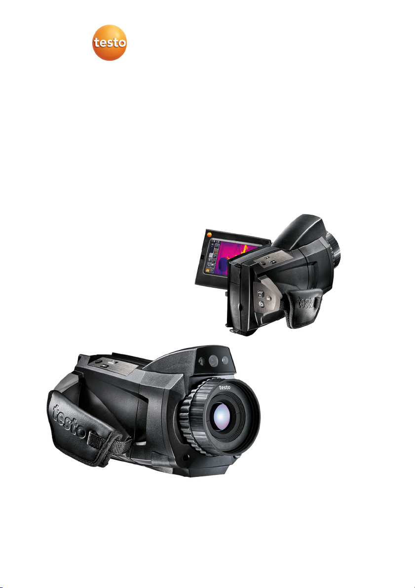
testo 885 · Thermal imager
Instruction manual
www.GlobalTestSupply.com
Page 2

2
www.GlobalTestSupply.com
Page 3

1 Contents
1 Contents
1 Contents ................................................................................................... 3
2 Safety and the environment .................................................................... 5
2.1. About this document ........................................................................ 5
2.2. Ensure safety ................................................................................... 6
2.3. Protecting the environment .............................................................. 7
3 Specifications .......................................................................................... 8
3.1. Use .................................................................................................. 8
3.2. Technical data ................................................................................. 9
4 Product description ............................................................................... 14
4.1. Overview........................................................................................ 14
4.1.1. Product components ...................................................................................... 14
4.1.2. Display interface ............................................................................................ 16
4.1.3. Operating concept ......................................................................................... 18
4.2. Basic properties ............................................................................. 19
4.2.1. Power supply ................................................................................................. 19
4.2.2. File formats and file names ............................................................................ 19
5 First steps .............................................................................................. 20
5.1. Commissioning .............................................................................. 20
5.1.1. Connecting the rechargeable battery ............................................................. 20
5.1.2. Performing basic settings ............................................................................... 20
5.1.3. Initial charging of the rechargeable battery .................................................... 22
5.2. Getting to know the product ........................................................... 23
5.2.1. Adjusting the hand strap ................................................................................ 23
5.2.2. Attaching the lens cover to the hand strap ..................................................... 24
5.2.3. Rotating the handle ........................................................................................ 25
5.2.4. Attaching a shoulder strap ............................................................................. 26
5.2.5. Using a lens case .......................................................................................... 26
5.2.6. Inserting the memory card ............................................................................. 27
5.2.7. Fitting/removing IR protection glass ............................................................... 27
5.2.8. Changing the lens .......................................................................................... 28
5.2.9. Switching the imager on/off ............................................................................ 29
5.2.10. Manually focusing the image .......................................................................... 29
5.2.11. Automatically focusing the image ................................................................... 30
5.2.12. Recording (freezing/saving) an image ............................................................ 30
3
www.GlobalTestSupply.com
Page 4

1 Contents
6
Using the product ................................................................................. 31
6.1. Menu bar/tabs ............................................................................... 31
6.1.1. Analysis functions tab .......................................................................... 31
6.1.2. Scale and correction functions tab ....................................................... 31
6.1.3. Main menu tab ..................................................................................... 32
6.2. Menu functions .............................................................................. 35
6.2.1. Measurement ................................................................................................. 35
6.2.2. Display options .............................................................................................. 44
6.2.3. Image gallery ................................................................................................. 46
6.2.4. Wizards ......................................................................................................... 49
6.2.5. Configuration ................................................................................................. 52
6.2.6. Audio (only testo 885-2) ................................................................................. 59
6.3. Measuring ..................................................................................... 61
7 Maintaining the product ....................................................................... 62
8 Tips and assistance .............................................................................. 63
8.1. Questions and answers ................................................................ 63
8.2. Accessories and spare parts ......................................................... 64
4
www.GlobalTestSupply.com
Page 5
2 Safety and the environment
2 Safety and the environment
2.1. About this document
Use
> Please read this documentation through carefully and
familiarize yourself with the product before putting it to use. Pay
particular attention to the safety instructions and warning advice
in order to prevent injuries and damage to the products.
> Keep this document to hand so that you can refer to it when
necessary.
> Hand this documentation on to any subsequent users of the
product.
Warnings
Always pay attention to information that is marked by the following
warnings with warning pictograms. Implement the specified
precautionary measures.
Representation Explanation
CAUTION
NOTICE
indicates potential minor injuries
indicates circumstances that may lead to
damage to the products
Symbols and writing standards
Represen-
Explanation
tation
Note: Basic or further information.
1. ...
Action: more steps, the sequence must be followed.
2. ...
> ... Action: a step or an optional step.
- ... Result of an action.
Menu Elements of the instrument, the instrument displays
or the program interface.
5
www.GlobalTestSupply.com
Page 6

2 Safety and the environment
[OK] Control keys of the instrument or buttons of the
2.2. Ensure safety
... | ... Functions/paths within a menu.
“...” Example entries
program interface.
> Only operate the product properly, for its intended purpose and
within the parameters specified in the technical data. Do not
use any force.
> Do not operate the instrument if there are signs of damage at
the housing, mains unit or feed lines.
During operation, the imager must not be pointed at the sun or
other intensive sources of radiation (e.g. objects with temperatures
greater than 550°C/1022°F, if using the high-temperature
measurement range 1400°C/2552°F). This can lead to serious
damage to the detector. The manufacturer assumes no liability for
any such damage to the microbolometer detector.
> The objects to be measured or the measurement environment
may also pose risks: Note the safety regulations valid in your
area when performing the measurements.
> Do not store the product together with solvents. Do not use any
desiccants.
> Carry out only the maintenance and repair work on this
instrument that is described in the documentation. Follow the
prescribed steps exactly. Use only original spare parts from
Testo.
> Improper use of rechargeable batteries can lead to destruction
or injuries by means of current surges, fire or escaping
chemicals. The following instructions must be observed to avoid
such hazards:
• Only use in accordance with the directions in the instruction
manual.
• Do not short, take apart or modify.
• Do not expose to heavy impacts, water, fire or temperatures
above 60 °C.
• Do not store in the proximity of metal objects.
6
www.GlobalTestSupply.com
Page 7

• Do not use leaky or damaged rechargeable batteries. In the
event of contact with battery acid: Thoroughly wash affected
area with water and consult a doctor, if necessary.
• Only charge in the instrument or the recommended charging
station.
• Immediately stop the charging process if this is not
completed in the given time.
• In the event of improper function or signs of overheating,
immediately remove the rechargeable battery from the
measuring instrument/charging station. Caution:
2.3. Protecting the environment
Rechargeable battery may be hot!
> Dispose of faulty rechargeable batteries/spent batteries in
accordance with the valid legal specifications.
> At the end of its useful life, send the product to the separate
collection for electric and electronic devices (observe local
regulations) or return the product to Testo for disposal.
2 Safety and the environment
7
www.GlobalTestSupply.com
Page 8

3 Specifications
3 Specifications
3.1. Use
The testo 885 is a handy and robust thermal imager. It enables you
to carry out contactless determination and display of the
temperature distribution on surfaces.
Typical areas of application are:
• Building inspection: energetic assessment of buildings, and
inspection of heating, ventilation and air conditioning systems.
• Preventative maintenance (servicing): mechanical and electrical
inspection of systems, machines and energy distribution
systems
• Production monitoring (quality assurance): monitoring of
production processes
• Professional energy consultation, leak detection
• Checking of photovoltaic modules
The testo 885 is available in several versions, which are tailored to
various usage requirements:
• testo 885-1: high-quality wide angle lens 30° x 23, detector 320
x 240, NETD < 30 mK at 30°C, 2GB SD card for approx. 2000
to 3000 images, SuperResolution with 640 x 480 pixels
(optional), minimum focusing distance 0.1 m, touchscreen, builtin digital imager with power LEDs for illumination, auto-focus,
isotherm, min/max/avg on area, image stitching wizard, laser
(not available in all countries), rotatable handle, rotatable and
pivoting display
• testo 885-2, additional/different functions/features: telephoto
lens (optional), display of the surface moisture distribution
through manual entry of the environmental conditions (optional:
humidity measurement in real time with radio humidity probe),
site recognition with image management, voice recording, high
temperature measurement (optional), full radiometric video
measurement (optional)
Export control
Thermal imagers may be subject to the export restrictions of the
European Union.
Please observe the national regulations for export control when
exporting.
8
www.GlobalTestSupply.com
Page 9

3.2. Technical data
3 Specifications
Infrared image output
Feature Values
Detector type FPA 320 x 240 pixels, a.Si
Thermal sensitivity
< 30 mK at 30°C (86°F)
(NETD)
Field of vision/min.
focusing distance
30° x 23°/0.1 m (0.33 ft)
Telephoto lens (optional): 11° x 9°/0.5 m
(1.64 ft)
Geometric resolution
(IFOV)
Super-resolution
(pixels/IFOV) optional
1.7 mrad (standard lens)
0.6 mrad (telephoto lens)
640 x 480 pixels /
1.06 mrad (standard lens)
0.38 mrad (telephoto lens)
Image refresh rate 33 Hz within EU, 9 Hz outside of EU
Focus Automatic/manual
Spectral range 8 - 14 μm
Visual image output
Feature Values
Image size 3.1 megapixels
Min. focusing
0.5 m (1.64 ft.)
distance
Image presentation
Feature Values
Image display
LCD touchscreen, 10.9 cm (4.3") screen
diagonal, 480 x 272 pixels
Digital zoom 1-3x
Display options IR image/real image
Video output USB 2.0
Video stream Max. 25 Hz within EU, max. 9 Hz outside EU
Colour palettes 9
9
www.GlobalTestSupply.com
Page 10
3 Specifications
Measurement
Feature Values
Temperature ranges
(can be changed)
-20 to 100°C (-4 to 212°F)
0 to 350°C (32 to 662°F)
Only testo 885-2, optional:
350 to 1200°C (662 to 2192°F)
Accuracy
±2°C (±3.6°F) or ±2% of meas. val. (higher
value applies)
Reproducibility ±1°C (±1.8°F) or ±1% (higher value applies)
Emissivity/reflected
0.01 to 1.00
temperature settings
Reflected
Manual
temperature/transmis
sion correction
(atmosphere)
settings
Minimum measuring
point diameter
Measurement
Standard lens: 5.0 mm with 1 m distance
Telephoto lens: 1.9 mm at 1 m distance
Feature Values
Display of surface
moisture distribution
Humidity
measurement with
radio humidity probe
Only testo 885-2:
via manual input
Only testo 885-2, optional:
automatic measurement value transfer in
real time
(not available in all
countries)
Solar mode Yes
Analysis functions
Up to 3 measuring points, hot/coldspot
detection, area measurement
(min-/max-/average value), isotherm, alarms
10
www.GlobalTestSupply.com
Page 11

3 Specifications
Imager equipment
Feature Values
Digital imager Yes
Standard lens 30° x 23°
Telephoto lens Optional: 11° x 9°
Site recognition with
Only testo 885-2
image management
Image stitching
Yes
wizard
Laser (not available
635 nm, Class 2
in USA, Japan,
China)
Voice recording
Only testo 885-2: via Bluetooth (not
available in all countries)/via wired headset
Video measurement
Up to 3 measuring points
(via USB)
Full radiometric video
Only testo 885-2 (optional)
measurement (via
USB)
Image storage
Feature Values
File format
.bmt, possible export to .bmp, .jpg, .png,
.csv, .xls
Video file format (via
USB)
.wmv, .mpeg-1 / only testo 885-2: vmt (full
radiometric video, testo format)
Storage device SD card 2 GB (800 to 1000 images)
11
www.GlobalTestSupply.com
Page 12
3 Specifications
Power supply
Feature Values
Battery type
Fast-charging Li-ion battery can be changed
on site
Operating time Approx. 4.5 h at 20 to 30°C (68 to 86°F)
Charging option In instrument/in charging station (optional)
Mains operation Yes, with mains unit 0554 8808
Mains unit output
5 V / 4 A
voltage
Ambient conditions
Feature Values
Operating
-15 to 50°C (5 to 122°F)
temperature range
Storage temperature
-30 to 60°C (-22 to 140°F)
range
Air humidity 20 to 80% non-condensing
Physical features
Feature Values
Weight 1570 g (including battery)
Dimensions (L x W x
253 x 132 x 111 mm (0.83 x 0.44 x 0.37")
H)
Tripod mounting 1/4" - 20 UNC
Housing protection
IP54
class (IEC 60529)
Vibration
2G
(IEC 60068-2-6)
12
www.GlobalTestSupply.com
Page 13

3 Specifications
Bluetooth (not available in all countries)
Feature Values
Type designation BlueGiga WT 11
Product note WT 11
Identification B01867
Company 10274
Information of the
FCC (Federal
Communications
Commission)
Operating
information
Guidelines, warranty
Feature Values
EU Directive 2004/108/EC
Warranty
This device fulfils part 15 of the FCC
guidelines. Commissioning is subject to the
two following conditions: (1) This instrument
must not generate any dangerous
interference and (2) this instrument must be
able to receive interference, even if this
could have undesired effects on operation.
Changes and modifications to the
instrument that have not been expressly
approved by testo AG may nullify the user's
right to use the instrument.
You can switch off Bluetooth at any time if
you wish to save battery power or if the use
of radio links is not permitted, e.g. in aircraft
or hospitals.
2 years, warranty conditions: see
www.testo.com/warranty
13
www.GlobalTestSupply.com
Page 14
4 Product description
4 Product description
4.1. Overview
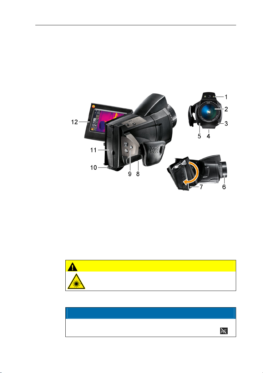
4.1.1. Product components
14
1 Digital imager lens for taking visual images and two
power -LEDs for illuminating the image.
2 Infrared imager lens for taking thermograms.
3 [Release lens] for releasing the lens lock.
4 Thread (1/4" - 20 UNC) for attaching a tripod (bottom of
imager). Do not use desktop tripods: danger of tipping over!
5 Laser (not available in all countries) for marking the
measurement object.
CAUTION
Laser radiation! Class 2 laser
> Do not look into the beam.
6 Focusing ring for adjusting the focus manually.
CAUTION
Auto mechanism may be damaged!
> Only turn focusing ring when auto-focus is deactivated (
www.GlobalTestSupply.com
).
Page 15
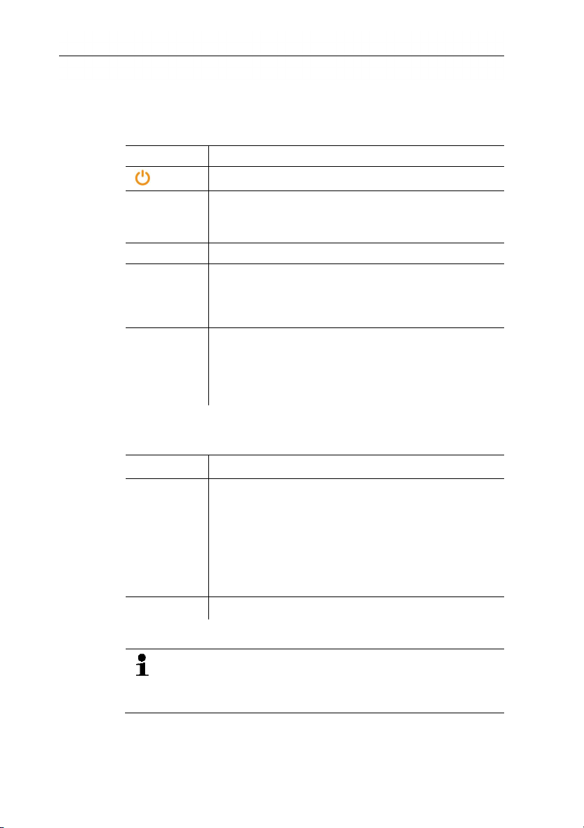
4 Product description
7 Rotatable handle with adjustable hand strap and fastening loop
for the lens cover.
8 Battery compartment (bottom of imager).
9 Operating buttons (back and top of imager):
Button Functions
[]
[●] (5-way
joystick)
Switch imager on/off
Press [●]: open menu, activate selection/setting.
Move [●] up/down/right/left: select functions,
navigate
[Esc]
Cancel action.
[A], [B] Shortcut keys for activating various functions. The
current shortcut key assignment is displayed (top
left). For adjustable functions, see Configure key,
page 56.
[Trigger
button]
(round
Press button (only when auto-focus is activated):
focus image automatically.
Press button: record image (freeze/save).
unmarked
button)
10 Two fixing eyelets for carrying/shoulder strap.
11 Interface terminals:
Terminal Assignment
Top
Mains socket, headset socket, Battery status LED.
Battery status LED indications (imager on):
• Off (no battery inserted).
• Flashing (mains unit is connected and battery is
charging).
• On (mains unit is connected and battery is fully
charged).
Bottom USB port, memory card slot.
12 Display, can be flipped out 90° and rotated 270°.
When the imager is switched on, the display remains active
even when folded in. It is advisable to use the power-save
options to prolong the battery life, see Power-save options,
15
page 57.
www.GlobalTestSupply.com
Page 16
4 Product description
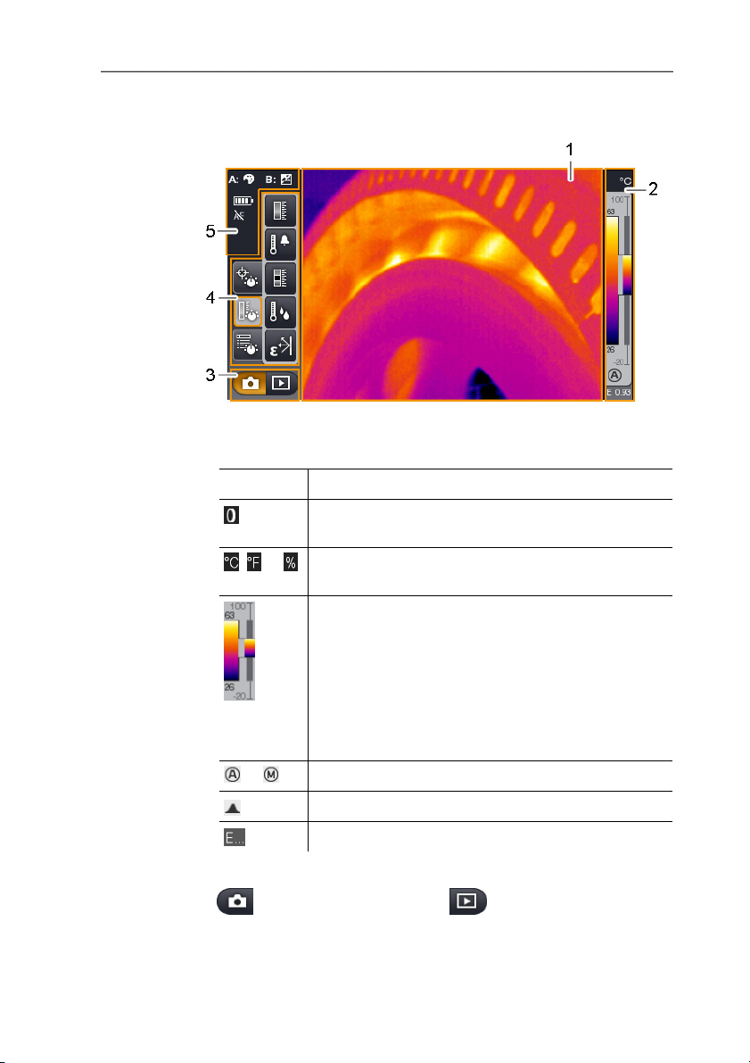
4.1.2. Display interface
1 Image display: shows IR image or real image.
2 Scale display:
Display Description
Protection glass function activated. No symbol
when function is deactivated.
, or
Selected unit for measurement value and scale
displays.
Left: temperature margin of the image displayed,
showing the minimum/maximum measurement
value (with automatic scale adjustment) or the
selected minimum/maximum display value (with
manual scale adjustment).
Right: temperature margin of the image displayed,
based on the set measurement range, showing
the measurement range limits.
or
Automatic or manual scale adjustment activated.
Histogram adjustment activated.
Set emissivity.
3 Imager mode selection bar:
button for recording mode, button for image gallery
mode.
16
www.GlobalTestSupply.com
Page 17
4 Product description
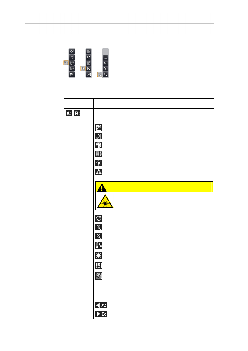
4 Menu bar: the menu bar comprises 3 tabs including buttons for
selecting functions:
Further information is available under Menu bar/tabs, page 31.
5 Status displays:
Display Description
,
Possible shortcut key functions (to change the
assignment, see Configure key, page 56):
: Image type.
: Emissivity.
: Palette.
: Scale.
: Power -LEDs.
: Laser.
CAUTION
Laser radiation! Class 2 laser
> Do not look into the beam.
: Adjustment.
: Zoom in.
: Zoom out.
: Humidity
: Solar
: Image stitching
: Site recognition
When viewing a saved image in the single image
view of the image gallery, the function buttons are
permanently assigned the following functions:
: display previous image.
: display next image.
17
www.GlobalTestSupply.com
Page 18
4 Product description
Display Description
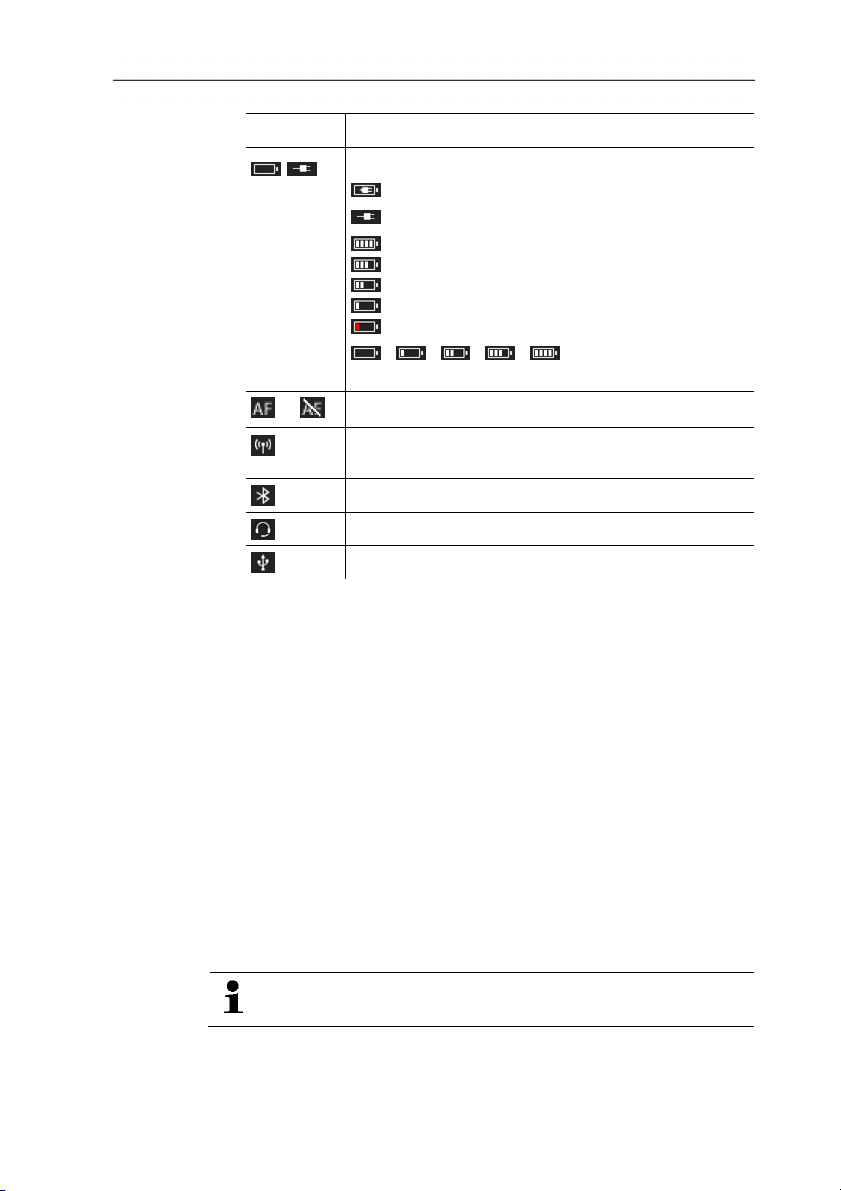
,
Power supply/battery capacity:
: Mains operation, battery fully charged.
: Mains operation, no battery inserted.
: Battery operation, capacity 75-100%
: Battery operation, capacity 50-75%
: Battery operation, capacity 25-50%
: Battery operation, capacity 10-25%
: Battery operation, capacity 0-10%.
- - - - (animated): battery is
charging.
or
Auto-focus activated or deactivated.
Only testo 885-2: radio link to radio probe
established.
Only testo 885-2: Bluetooth interface activated.
Only testo 885-2: headset connected.
USB connection established.
4.1.3. Operating concept
The imager can be operated in two different ways.
Operation via touchscreen offers quick access to functions.
Operation via joystick requires more actions but enables singlehanded operation of the imager.
18
Joystick operation
Selection and activation is carried out in two steps: moving the
joystick ( [●] ) up/down/right/left moves the orange selection box on
the display. The selected function or button is activated by pressing
the joystick.
Touchscreen operation
Selection and activation is carried out in one step: the required
function or button is selected at the touch of a fingertip and is
activated at the same time.
Capacitive touchscreen. Operation is only possible with a
bare fingertip (no gloves) or a conductive stylus pen.
www.GlobalTestSupply.com
Page 19

Illustration in this document
To carry out the basic settings, examples of both methods of
operation are given, describing all steps, see Performing basic
settings, page 20.
The other chapters only deal with functions/buttons that have to be
activated:
• Touchscreen operation: touch with a fingertip.
• Joystick operation: select first (move joystick up/down/right/left),
4.2. Basic properties
then activate (press joystick).
4.2.1. Power supply
The power is supplied to the instrument via a replaceable
rechargeable battery or via the mains unit provided.
With an attached mains unit, power is supplied automatically via
the mains unit and the instrument's rechargeable battery is charged
(only at ambient temperatures from 0 to 40°C).
Under high ambient temperatures a longer charging time
may be required.
Charging the battery is also possible using a desktop charging
station (accessory: 0554 8851).
The instrument is equipped with a buffer battery to maintain the
system data during an interruption in the power supply (e.g. when
the battery is changed).
4 Product description
4.2.2. File formats and file names
All saved images consist of an IR image and the attached real
image.
The images are saved according to the following pattern:
XXyyyyyy.zzz
XX: IR for all single images (standard), ST for a package including
several single images (recorded with the image stitching wizard).
yyyyyy: 6-digit sequential number.
zzz: bmt for all images (Testo-specific file extension).
19
www.GlobalTestSupply.com
Page 20
5 First steps
5 First steps
5.1. Commissioning
5.1.1. Connecting the rechargeable battery
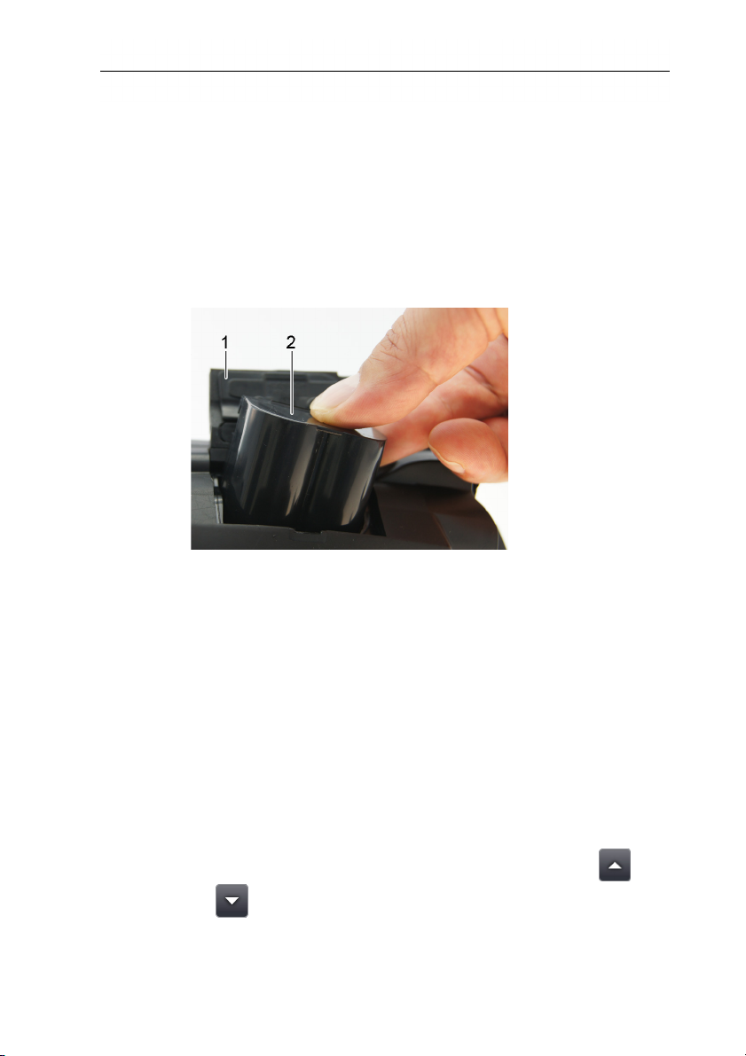
1. Open battery compartment cover (1).
2. Slide rechargeable battery (2) fully into the battery compartment
until it clicks into place.
-
T
h
e
i
m
a
g
e
r
s
- The imager starts automatically.
3. Close the battery compartment cover.
5.1.2. Performing basic settings
> Flip open the display and remove the protective film.
- The start screen appears on the display.
- When you first switch on the imager: the Country settings and
Set time/date dialogue boxes are opened one after the other to
set the instrument language, temperature unit (°C/°F) and
time/date.
Touchscreen operation
✓ The Country settings dialogue box is opened.
1. Touch the required language. If necessary, scroll with
to display other languages.
- The activated language is indicated with a tick.
20
www.GlobalTestSupply.com
/
Page 21
5 First steps
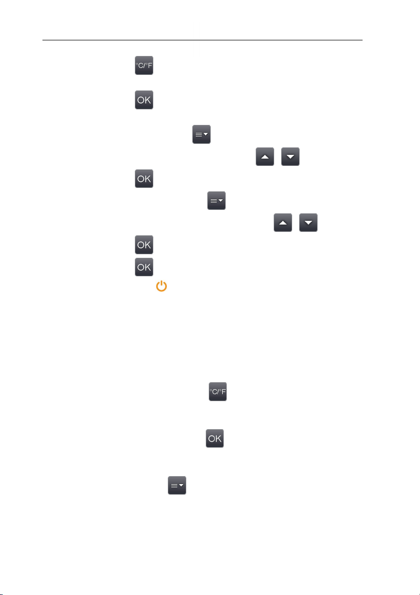
2. Touch to change the unit.
- The activated unit is shown on the top right of the display.
3. Touch to confirm the entry.
- The Set time/date dialogue box is opened.
4. Touch the top button
to open the Time input screen.
5. Set values for Hour and Minute with / .
6. Touch
to confirm the entry.
7. Touch the bottom button to open the Date input screen.
8. Set values for Day, Month and Year with / .
9. Touch
10. Touch
to confirm the entry.
to close the input screen.
> Hold down [] to close the imager.
Joystick operation
✓ The Country settings dialogue box is opened.
1. Move [●] up/down to select the required language.
- An orange box appears around the selected language.
2. Press [●] to activate the selection.
- The activated language is indicated with a tick.
3. Move [●] left/up to select .
4. Press [●] to change the unit.
- The activated unit is shown on the top right of the display.
5. Move [●] down to select
.
6. Press [●] to activate the selection.
- The Set time/date dialogue box is opened.
- The top button
is selected.
7. Press [●] to open the Time input screen.
8. Move [●] up/down to set the values for Hour and Minute. To
toggle between the parameters, move [●] left/right.
21
www.GlobalTestSupply.com
Page 22
5 First steps
9. Move [●] left to select
.
10. Press [●] to activate the selection and close the input screen.
11. Move [●] down to select the bottom button
.
12. Press [●] to open the Date input screen.
13. Move [●] up/down to set the values for Day, Month and Year.
To toggle between the parameters, move [●] left/right.
14. Move [●] left to select .
15. Press [●] to activate the selection and close the input screen.
16. Move [●] left to select .
17. Press [●] to activate the selection and close the input screen.
> Hold down [] to close the imager.
5.1.3. Initial charging of the rechargeable battery
The imager is delivered with a partially charged battery. Fully
charge the battery before use.
> Connect the country-specific adapter required for the existing
mains to the mains unit.
22
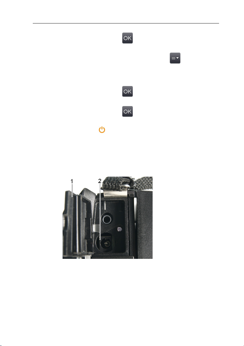
1. Open the cover of the top interface terminal (1).
2. Connect the mains unit to the mains socket (2).
www.GlobalTestSupply.com
Page 23
3. Connect the mains plug to a power socket.
- The imager starts automatically.
The rechargeable battery can be recharged with the imager
switched on or off. This has no effect on the time required
to charge the battery.
- Charging of the battery is started.
- The charge status is indicated by the status LED (3):
• LED flashes: charging in process.
• LED lights: battery charged, charging process finished.
4. Fully charge the battery, then disconnect the instrument from
the mains unit.
- After initial charging of the battery, the imager is ready for use.
A desktop charging station (accessory: 0554 8851) can also be
5.2. Getting to know the product
used to charge the battery.
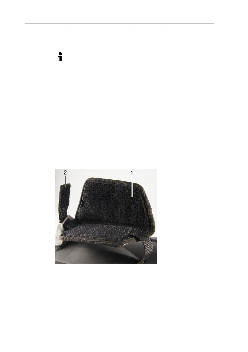
5.2.1. Adjusting the hand strap
5 First steps
> Lay the imager on its left side.
1. Open out the top of the hand strap padding (1).
2. Pull the fastening end of the strap up (2).
3. Put your right hand through the hand strap from the right-hand
side.
4. Adjust the hand strap by loosening/tightening it to fit your hand
and secure the fastening end again.
5. Fold down the top of the hand strap padding.
23
www.GlobalTestSupply.com
Page 24
5 First steps
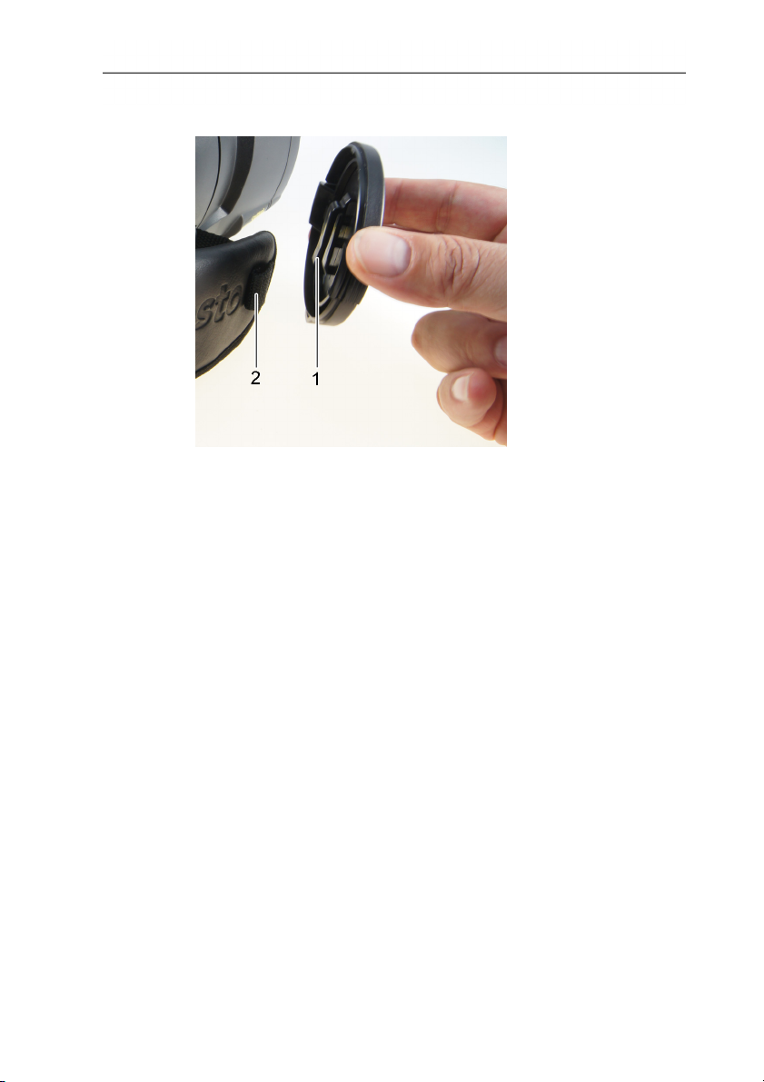
5.2.2. Attaching the lens cover to the hand strap
> Guide the clip on the lens cover (1) through the loop on the
handle (2).
24
www.GlobalTestSupply.com
Page 25
5.2.3. Rotating the handle
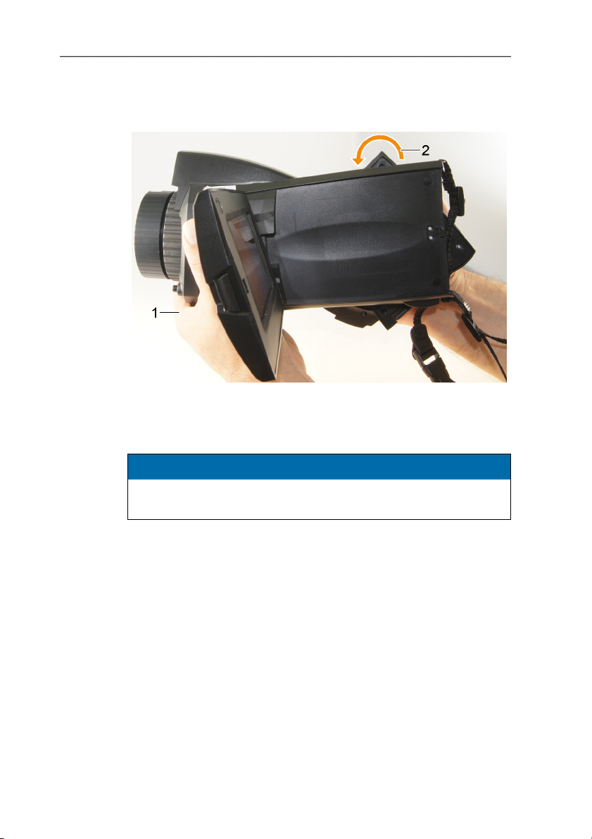
The handle can be rotated up to 180° in 10 positions.
1. Put your right hand through the hand strap.
2. Grip the imager with your left hand. To do this, hold the casing
at the front of the imager (1).
5 First steps
CAUTION
Display may be damaged!
> Do not hold the imager by the fold-out display.
3. Turn your right hand to move the handle to the required
position (2). Press down with your middle and ring finger. To
rotate in the opposite direction, press up with the heel of your
hand.
25
www.GlobalTestSupply.com
Page 26
5 First steps
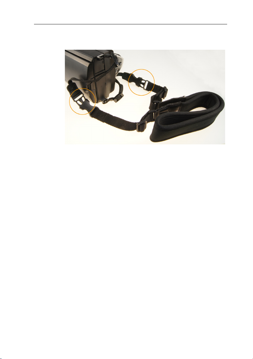
5.2.4. Attaching a shoulder strap
> Link together shoulder strap click locks and the carrying strap
attached to the imager.
5.2.5. Using a lens case
The lens case (included in the scope of delivery of the
interchangeable lens) is used to protect and transport the
interchangeable lens. It can be attached using the carabiner e.g. to
a belt loop.
To protect against damage to lenses not being used, the
transparent plastic cap must always be attached to the back of the
lens. Make sure that the case zip is properly zipped up.
26
www.GlobalTestSupply.com
Page 27
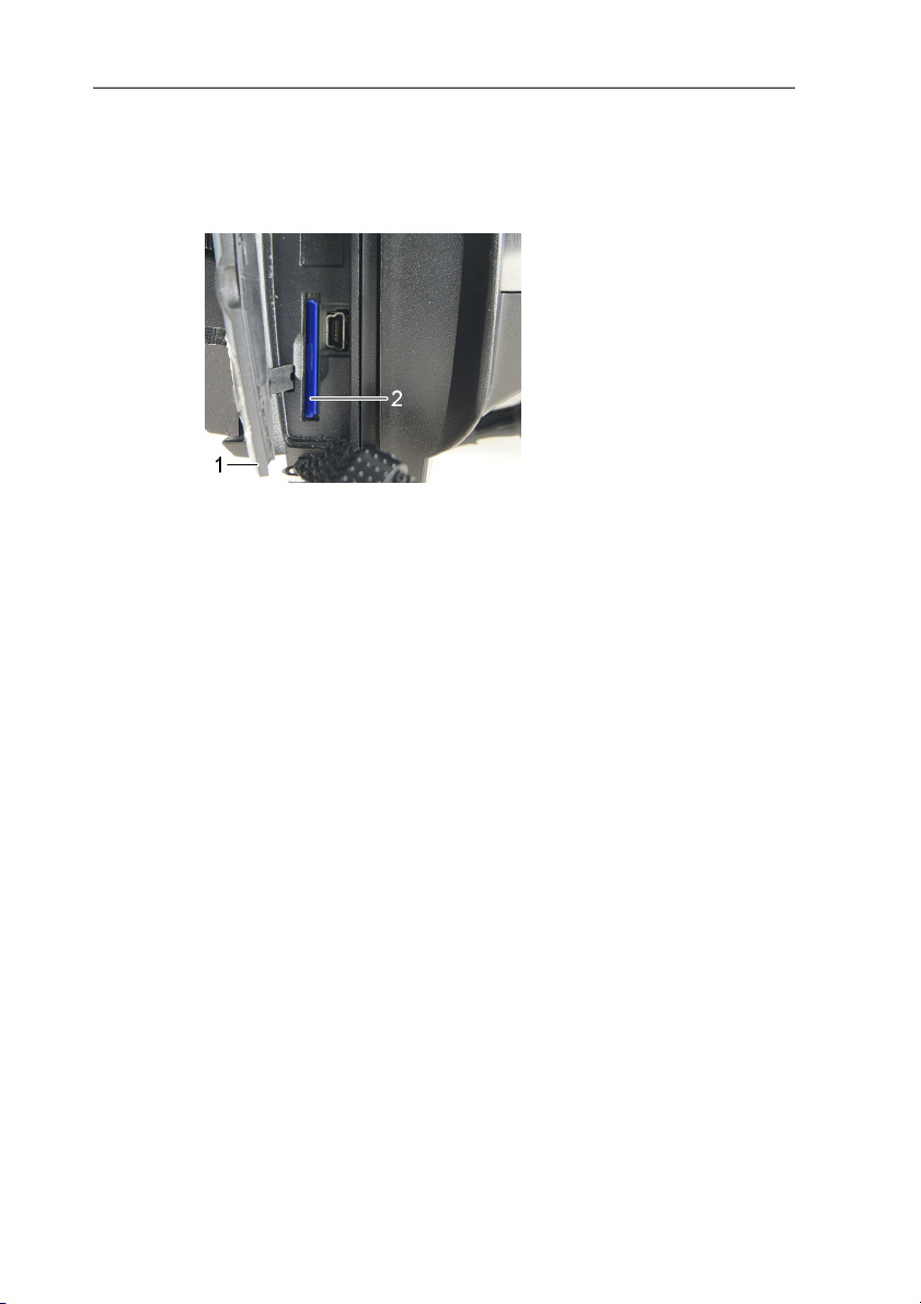
5.2.6. Inserting the memory card
1. Open the cover of the bottom interface terminal (1).
2. Push the memory card (SD or SDHC card) into the card slot (2).
5 First steps
> To remove the memory card: press the memory card to release
the lock.
5.2.7. Fitting/removing IR protection glass
The lens focusing ring has an internal thread for fitting the
protection glass.
Fitting
> Insert the protection glass into the lens focusing ring and turn
clockwise as far as it will go.
Removing
> Turn the protection glass anti-clockwise and remove it.
After fitting or removing the protection glass, activate or deactivate
the Protection glass option, see Optics, page 56. If this option is
set incorrectly, the specified measuring accuracy is not guaranteed.
27
www.GlobalTestSupply.com
Page 28
5 First steps
5.2.8. Changing the lens
Only lenses that have been adjusted to the respective thermal
imager can be used. The serial number on the lens must match the
serial number displayed in the imager, see Optics, page 56.
> Place the imager on a stable base.
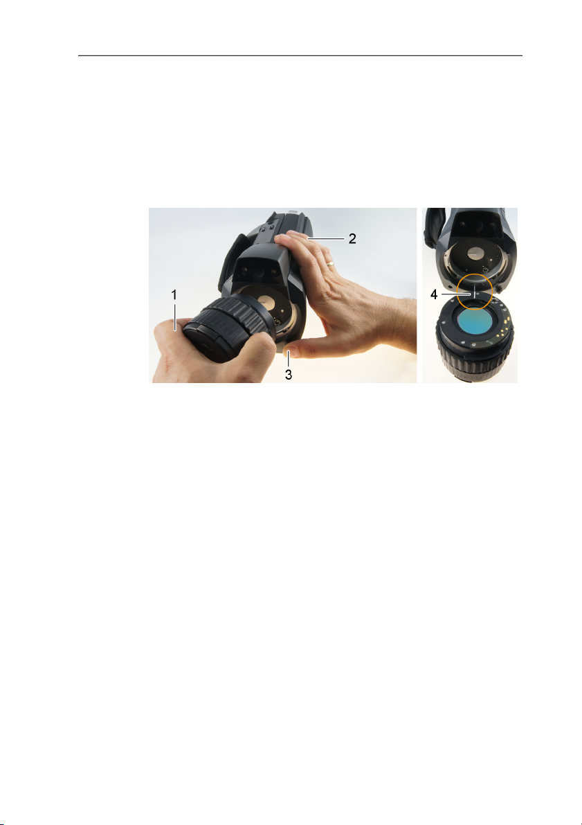
Removing the lens
1. Grip the lens with your left hand (1), hold the imager with your
right (2) and press [Release lens] (3).
2. Unscrew lens by turning it anti-clockwise and remove.
Always keep lenses in the lens case (included in the scope of
delivery of the interchangeable lens) while they are not in use.
Attaching a new lens
1. Grip the lens with your left hand (1) and hold the imager with
your right (2).
2. Line up the marks on the lens and the instrument (4) and place
the lens in the lens mount.
3. Push the lens into the mount as far as it will go and turn it
clockwise until it clicks into place.
28
www.GlobalTestSupply.com
Page 29
5.2.9. Switching the imager on/off
1. Remove protection cap from the lens.
2. Press [ ].
- The start screen appears on the display. Instrument information
is displayed (e.g. serial number, type designation, firmware
version).
- The measurement view is opened. Measurement values on the
cursor and scale are only displayed when the stabilisation
phase is complete (indicated by a rotating symbol in the top
right of the display).
- The imager performs automatic adjustment approx. every 60 s.
This can be recognized by means of a "click". The image is
frozen briefly when this occurs.
> To switch off: Hold down [
no longer displayed.
5.2.10. Manually focusing the image
- The imager is switched off.
CAUTION
Auto mechanism may be damaged!
> Only turn focusing ring when auto-focus is deactivated (
] until the confirmation prompt is
5 First steps
).
> Deactivate auto-focus: | .
- is displayed.
29
> Turn the lens focusing ring until the image is in sharp focus.
www.GlobalTestSupply.com
Page 30
5 First steps
5.2.11. Automatically focusing the image
> Activate auto-focus: | .
- - is displayed and is highlighted orange.
> Touch [Trigger button].
- The image is automatically focussed. The area to be focussed
must be inside the orange box, which is shown by touching the
trigger button.
5.2.12. Recording (freezing/saving) an image
1. Press the [Trigger button].
- The image is frozen (still).
If you want to save the image, touch to select where you want
to save it to, see Image gallery, page 46.
2. Save image: press [Trigger button] again or touch
- The IR image is saved and the real image is automatically
attached to the IR image.
> Do not save image: press [Esc].
.
30
www.GlobalTestSupply.com
Page 31
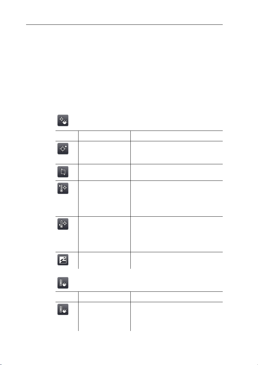
6 Using the product
6.1. Menu bar/tabs
Functions are called up via the menu bar. The menu bar comprises
3 tabs. Different functions are available depending on which tab is
selected.
Tabs and functions are described briefly below. Detailed
information about the individual functions is given in the following
chapters.
6.1.1. Analysis functions tab
Button Function Description
New mark
Insert new measuring point mark.
See also Pixel mark | New mark,
page 36.
Min/Max on Area
Hotspot
Show area mark. See also
Min/max/avg on area, page 37.
Display maximum measurement
value. When the function is enabled,
the button is highlighted orange.
See also Pixel mark | Hotspot, page
35.
Coldspot
Display minimum measurement
value. When the function is enabled,
the button is highlighted orange.
See also Pixel mark | Coldspot,
page 36.
Image type Change display: toggle between IR
image and real image.
6 Using the product
6.1.2. Scale and correction functions tab
Button Function Description
Scale Open Scale manual input screen.
31
www.GlobalTestSupply.com
To adjust the measurement value
scale. See also Scale manual, page
43.
Page 32
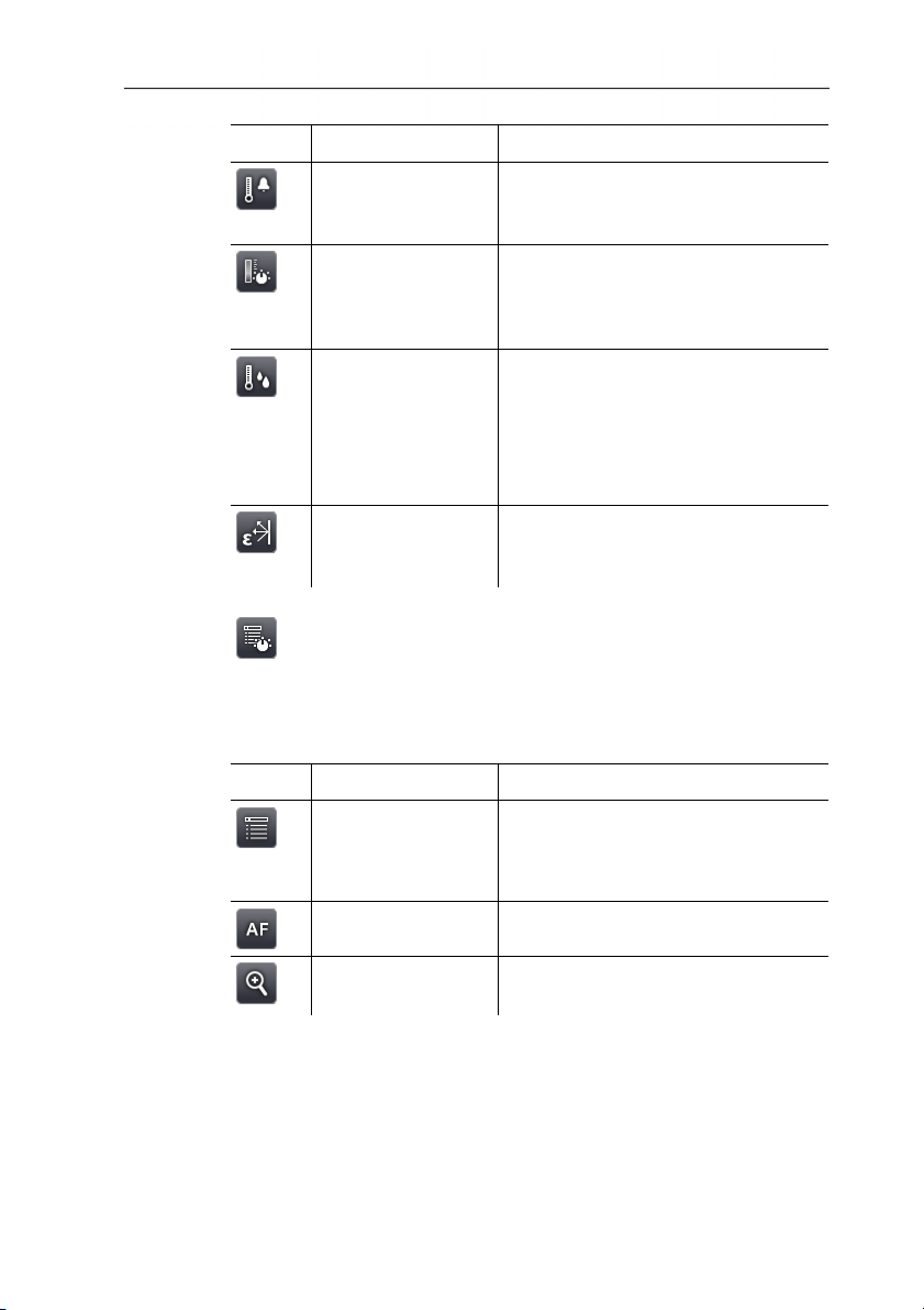
6 Using the product
Button Function Description
Alarm Open Alarm input screen. To set
Isotherm Open Isotherm input screen. To set
Humidity
Emissivity Open Emissivity input screen. To
6.1.3. Main menu tab
The displayed functions on the tab differ depending on the current
view.
the limits and activate/deactivate the
function. See also Alarm, page 37.
the limits and activate/deactivate the
function. See also Isotherm, page
38.
Only testo 885-2:
Open Humidity input screen. To set
the parameters and
activate/deactivate the function See
also Humidity (only testo 885-2) ,
page 39.
set the parameters. See also
Emissivity, page 41.
32
View of current image
Button Function Description
Menu
Auto-focus Activate/deactivate auto-focus.
Open menu. Via the menu, most
functions from the 3 tabs and many
additional functions can be called
up. See Measurement, page 35.
Zoom in To zoom in on the image (digital
www.GlobalTestSupply.com
zoom, 5 increments).
Page 33
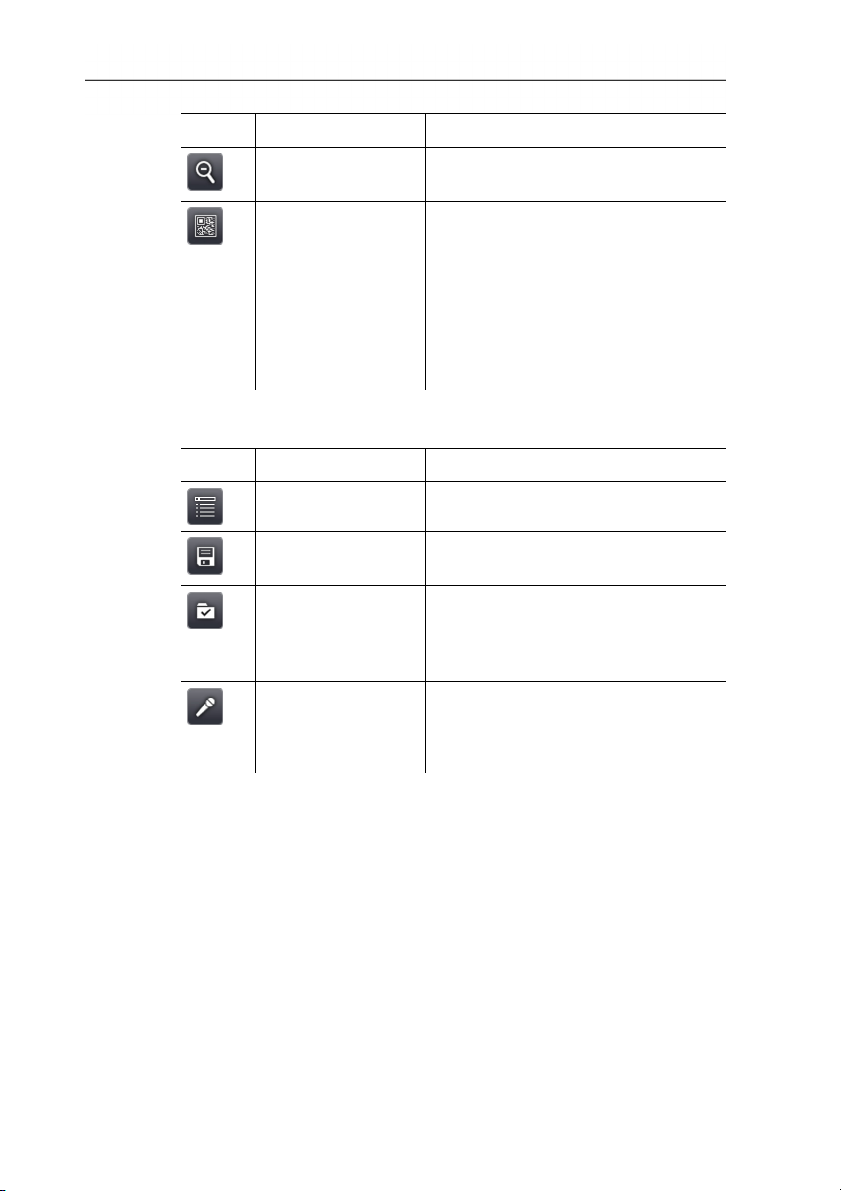
6 Using the product
Button Function Description
Zoom out To zoom out of the image to the full
Site recognition
image view.
Only testo 885-2:
To record site markers.
The button is not displayed as
default. It has to be re-activated
every time the imager is switched
on: call up the SiteRecognition
function again from the menu and
set a marker.
Frozen or saved image view
Button Function Description
Menu
See above.
Save Save image. Function only available
when the image is frozen.
Folder Open Folder input screen. To select
where to save images. Function
only available when the image is
frozen.
Audio
Only testo 885-2 when connected to
a headset: open Audio input
screen, see see Audio (only testo
885-2), page 59.
33
www.GlobalTestSupply.com
Page 34
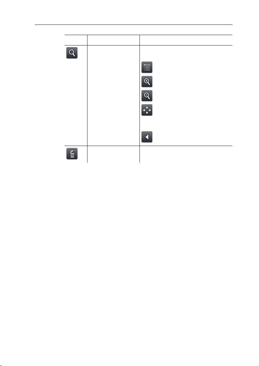
6 Using the product
Button Function Description
Sub-level zoom Sub-level zoom with additional
functions is displayed.
: menu, see above.
: zoom in, see above.
: zoom out, see above.
: display buttons for moving the
zoomed image. To move, touch the
buttons shown in the image.
: close sub-level zoom.
Delete image
Function only available when the
image is saved.
34
www.GlobalTestSupply.com
Page 35
6.2. Menu functions
6.2.1. Measurement
Measurement range
The measurement range can be set to adapt to the respective area
of application. If measurement range 3 is selected (hightemperature measurement range), the aperture in the lens is
automatically reduced to protect the detector against damage.
CAUTION
Detector may be damaged!
> If measurement range 1 and 2 are set: do not point the imager
at objects with temperatures above 550°C (1022°F).
> If measurement range 3 is set: do not point the imager at
objects with temperatures above 1400°C (2552°F).
Task Actions/description
Set the measurement
range.
6 Using the product
>
| | Measurement |
Measurement range | or
or
.
Pixel mark | Hotspot
Hotspot mark (crosshairs with maximum measurement value
displayed) can be shown.
Task Actions/description
Show/hide hotspot mark.
> | .
or
>
| | Measurement | Pixel
mark | Hotspot.
35
www.GlobalTestSupply.com
Page 36
6 Using the product
Pixel mark | Coldspot
The coldspot mark (crosshairs with minimum measurement value
displayed) can be shown.
Task Actions/description
Show/hide coldspot mark.
> | .
or
>
| | Measurement | Pixel
mark | Coldspot.
Pixel mark | New mark
Up to 3 measuring point marks (crosshairs with measurement
values displayed) can be shown and freely positioned.
Task Actions/description
Insert new mark.
> | .
or
>
| | Measurement | Pixel
mark | New mark.
Move crosshairs.
> Touch and drag crosshairs.
Joystick operation:
1. Select crosshairs and activate by
pressing the joystick.
2. Move crosshairs by moving the
joystick.
> To exit: Press joystick again and
activate Quit moving in the context
menu.
Hide crosshairs.
> Double-touch the crosshairs and
touch Hide in the context menu.
Joystick operation:
1. Select crosshairs and press joystick
twice.
2. In the context menu, activate Hide.
36
www.GlobalTestSupply.com
Page 37
6 Using the product
Min/max/avg on area
An area mark can be shown and freely positioned. The minimum
(min), maximum (max) and average (avg) measurement value in
this area is displayed.
Task Actions/description
Show area mark.
> | .
or
>
| | Measurement |
Min/Max on Area.
Move area mark.
> Touch and drag area mark.
Joystick operation:
1. Select area mark and activate by
pressing the joystick.
2. Move area mark by moving the
joystick.
> To exit: Press joystick again and
activate Quit moving in the context
menu.
Change size of area
mark/hide area mark.
> Press again.
Alarm
The alarm function shows all image points with measurement
values that exceed the upper alarm mark or fall below the lower
alarm mark in a single colour (alarm colour). To set the alarm
colours, see Colour selection, page 45.
Task Actions/description
Open Alarm input screen.
>
| .
or
Activate/deactivate Lower
alarm or Upper alarm.
>
> Active.
> To deactivate, touch the button
| | Measurement | Alarm.
again.
37
www.GlobalTestSupply.com
Page 38
6 Using the product
Task Actions/description
Set alarm values.
Apply entries.
Isotherm
The isotherm function shows all image points with measurement
values that lie within the set limits in a single colour (isotherm
colour). To set the isotherm colour, see Colour selection, page 45.
Task Actions/description
Open Isotherm input
screen.
> , .
> .
>
| .
or
>
| | Measurement |
Isotherm.
Activate/deactivate
isotherm display.
> Active.
> To deactivate, touch the button
again.
Set lower and upper
isotherm limit.
> , .
Link setting for
upper/lower limits.
> .
Apply entries.
> .
38
www.GlobalTestSupply.com
Page 39
6 Using the product
Humidity (only testo 885-2)
The ambient temperature and humidity values entered manually or
measured by the optional radio humidity probe are used to
calculate the relative surface moisture for each pixel. The values
can be shown as a humidity image. The special colour palette
indicates which areas are at risk of mould:
Colour Surface moisture Assessment
green 0…64%RH non-critical
yellow/ora
65 to 80%RH potentially critical
nge
red >80%RH critical
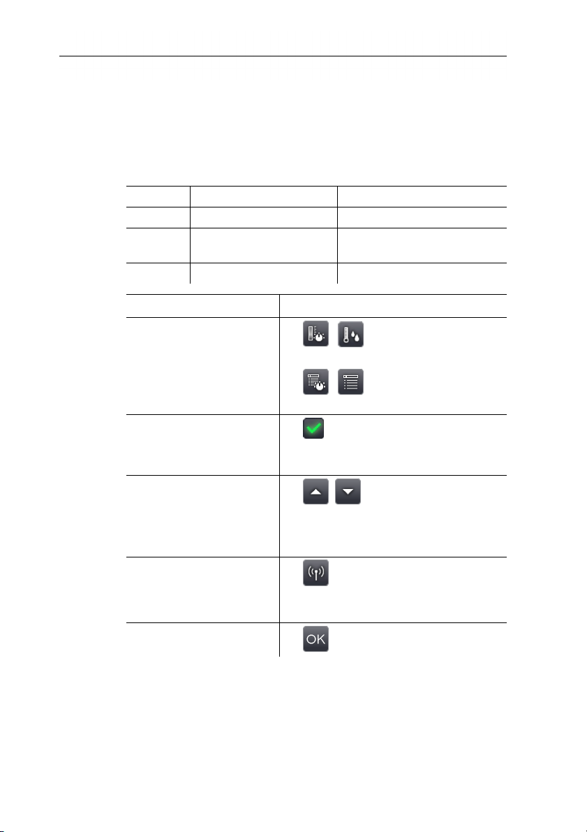
Task Actions/description
Open Humidity input
screen.
>
| .
or
> | | Measurement |
Humidity.
Activate/deactivate
humidity image display.
> Active.
> To deactivate, touch the button
again.
Set values manually for
ambient temperature
> , .
(Ambient temp.) and
ambient humidity
(Humidity):
Set up radio link to the
optional radio humidity
probe.
> .
Further information is available under
Radio (only testo 885-2), page 54.
Apply entries.
> .
39
www.GlobalTestSupply.com
Page 40
6 Using the product
Atmospheric correction
Measurement deviations arising due to high humidity or large
distances to the object to be measured can be corrected.
Correction parameters must be entered for this.
If the imager is connected to an optional radio humidity probe (only
testo 885-2), the ambient temperature and humidity are transferred
automatically. For connection to a radio humidity probe, Further
information is available under Radio (only testo 885-2), page 54..
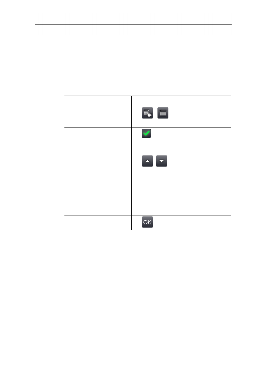
Task Actions/description
Open Atmospheric
correction input screen.
Activate atmospheric
correction.
Manually set the values
for the ambient
temperature
(Temperature), ambient
humidity (Humidity) and
distance between the
imager and the object to
be measured (Distance
to subject).
Apply entries.
> | | Measurement |
Atmospheric correction.
> Active.
> To deactivate, touch the button
again.
> , .
> .
40
www.GlobalTestSupply.com
Page 41
6 Using the product
Solar
To detect and document failures in photovoltaic systems, the solar
function can be selected. The sun's radiation intensity measured
(with an external instrument) can be entered for documentation
purposes. This value is saved with the IR- image.
If this function is activated, the entered value for the radiation
intensity is displayed (top left).
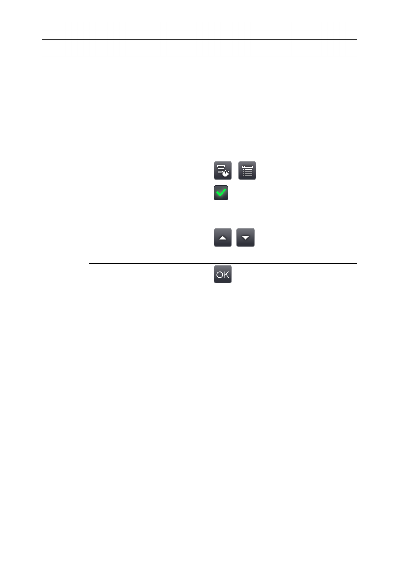
Task Actions/description
Open Solar input screen.
> | | Measurement | Solar.
Activate solar functions.
> Active.
> To deactivate, touch the button
again.
Manually set the value for
radiation intensity
> , .
(Temperature).
Apply entries.
> .
Emissivity
You can choose between user-defined emissivity and 8 materials
with set emissivity. The reflected temperature (RTC) can be set
individually.
Emissivity information:
The emissivity describes the capability of a body to emit
electromagnetic radiation. This is material-specific and must be
adapted for correct measurement results.
Non-metals (paper, ceramic, gypsum, wood, paints and coatings),
plastics and food have high emissivity, which means that the
surface temperature can be easily measured using infrared.
Because of their low or non-uniform emissivity, bright metals and
metal oxides only have limited suitability for infrared measurement.
Highly inaccurate measurements should be expected. A remedy for
this is coatings that increase emissivity, e.g. paint or emission
adhesive (accessory, 0554 0051), which must be applied to the
object to be measured.
The following table gives typical emissivities of important materials.
These values can be used as a guide for user-defined settings.
41
www.GlobalTestSupply.com
Page 42

6 Using the product
Material (material temperature) Emissivity
Aluminium, bright rolled (170°C) 0.04
Cotton (20°C) 0.77
Concrete (25°C) 0.93
Ice, smooth (0°C) 0.97
Iron, emery ground (20°C) 0.24
Iron with casting skin (20°C) 0.80
Iron with rolling skin (20°C) 0.77
Gypsum (20°C) 0.90
Glass (90°C) 0.94
Rubber, hard (23°C) 0.94
Rubber, soft grey (23°C) 0.89
Wood (70°C) 0.94
Cork (20°C) 0.70
Radiator, black anodised (50°C) 0.98
Copper, slightly tarnished (20°C) 0.04
Copper, oxidized (130°C) 0.76
Plastics: PE, PP, PVC (20°C) 0.94
Brass, oxidized (200°C) 0.61
Paper (20°C) 0.97
Porcelain (20°C) 0.92
Black paint, matt (80°C) 0.97
Steel, heat-treated surface (200°C) 0.52
Steel, oxidized (200°C) 0.79
Clay, burnt (70°C) 0.91
Transformer paint (70°C) 0.94
Brick, mortar, plaster (20°C) 0.93
Reflected temperature information:
Using this offset factor, the reflection is calculated out based on the
low emissivity, and the accuracy of the temperature measurement
with infrared instruments is improved. In most cases, the reflected
temperature is identical to the ambient air temperature. Only when
objects with strong emissions and much higher temperatures (such
as ovens or machines) are in proximity to the object being
42
www.GlobalTestSupply.com
Page 43
6 Using the product
measured should the radiation temperature of theses heat sources
be determined and used (e.g. using a globe thermometer). The
reflected temperature has little effect on objects with high
emissivity.
Using the PC software, other materials can be imported into
the instrument from an existing list.
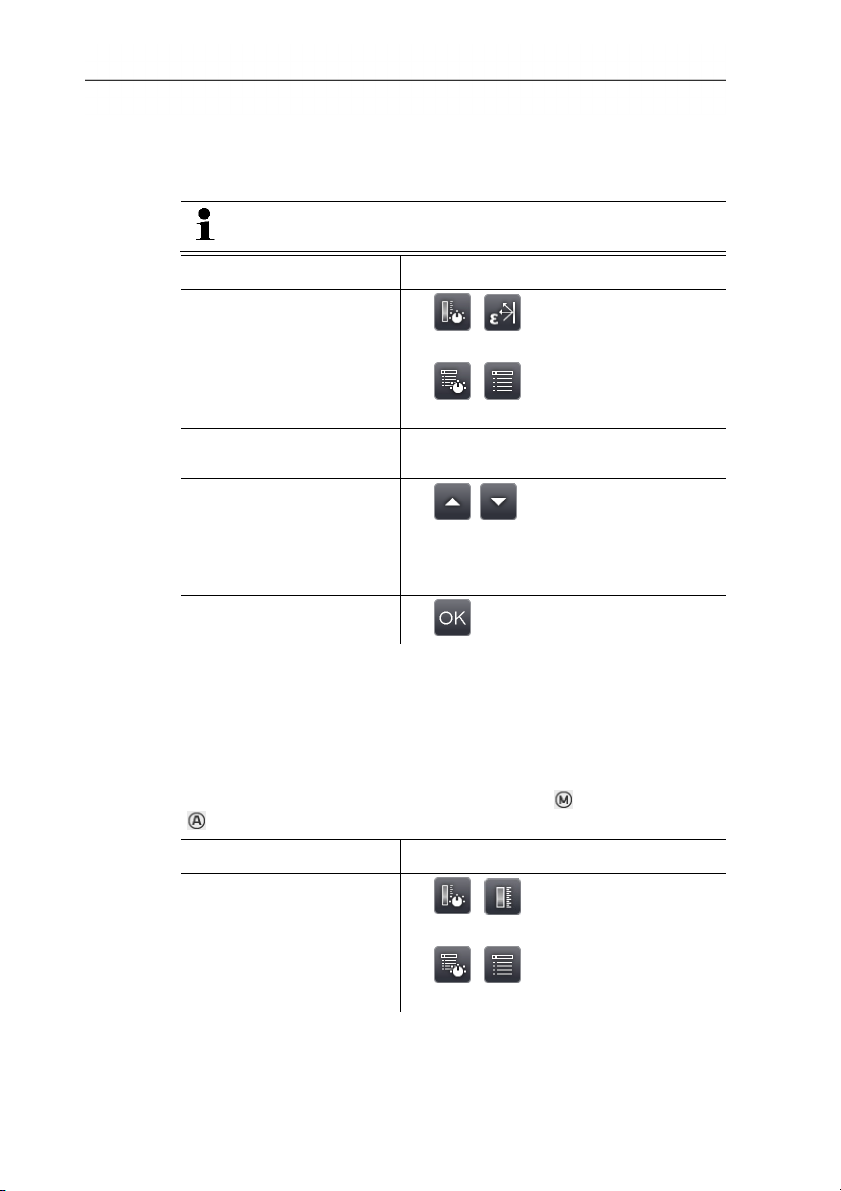
Task Actions/description
Open Emissivity input
screen.
>
| .
or
> | | Measurement |
Emissivity.
Select material.
> Highlight the material to be used by
touching on it.
Manually set the
emissivity (only when
> , .
User defined is selected)
and reflected temperature
(RTC).
Apply entries.
> .
Scale manual
Manual scaling can be activated instead of automatic scaling
(continuous automatic adjustment to the current min./max. values).
The scale limits can be set within the activated measurement range
(see Measurement range, page 35).
The activated mode is displayed bottom right: manual scaling,
automatic scaling.
Task Actions/description
Open Scale manual input
screen.
>
| .
or
>
| | Measurement | Scale
manual.
43
www.GlobalTestSupply.com
Page 44
6 Using the product
Task Actions/description
Activate/deactivate
manual scale adjustment.
Set scale limits.
Link setting for
upper/lower limits.
Apply entries.
6.2.2. Display options
Palette
You can choose from 8 existing colour palettes for the IR image
display.
Task Actions/description
Open Palette input
screen.
Select palette.
Apply entries.
> Active.
> To deactivate, touch the button
again.
> , .
> .
> .
> | | Display options |
Palette.
> Highlight the palette to be used by
touching it.
> .
44
www.GlobalTestSupply.com
Page 45
6 Using the product
Histogram adjustment
By adjusting the colour palette to the current temperature
distribution, histogram adjustment particularly in the case of scenes
with a large temperature scope (e.g. with high-temperature
measurements) increases the contrast.
When histogram adjustment is activated, the colours within
the scale are no longer distributed in a linear pattern
between the minimum and maximum scale value. It is
therefore difficult to draw conclusions about temperatures
from colours.
Task Actions/description
Activate/deactivate
Histogram adjustment.
>
| | Display options |
Histogram adjustment.
Colour selection
The colours used for the measurement functions Isotherm and
Alarm can be set.
Task Actions/description
Open Colour selection
input screen.
> | | Display options |
Colour selection.
Set required colour for
Isotherm, Top Alarm or
Bottom Alarm.
> .
> Activate colour to be used by
touching it.
Apply entries.
> .
45
www.GlobalTestSupply.com
Page 46
6 Using the product
6.2.3. Image gallery
The saved image can be viewed and analysed in the image gallery.
Folders can be created for saving new images to.
Only testo 885-2: it is possible to listen to and also subsequently
record or edit a voice commentary. Images with a voice
commentary are indicated with the following symbol:
Task Actions/description
Open image gallery.
.
> .
or
>
| | Image gallery.
Close image gallery.
> .
Navigation on the overview page
Task Actions/description
Open folder.
> Double-touch the symbol for the
folder to be opened.
One level up.
> .
Open single image view.
> Double-touch the preview image to
be opened.
For further information on the single
image view, see below.
46
www.GlobalTestSupply.com
Page 47

6 Using the product
Actions on the overview page
Task Actions/description
Create a new folder.
>
> Enter folder name.
> .
Delete folder or image.
1. Select folder or image by touching
on it.
2. .
3. Confirm deletion: .
Navigation in the single image view
✓ The single image view must be opened: see above.
Task Actions/description
Open main menu to
activate functions.
Display next or previous
> .
> [A] or [B].
image.
Back to overview page:
>
Close image gallery:
> [Esc].
| | Image gallery.
47
www.GlobalTestSupply.com
Page 48

6 Using the product
Actions in the single image view
✓ The single image view must be opened: see above.
Task Actions/description
Open main menu to
activate functions.
Delete image.
Record/edit voice
commentary (only testo
885-2).
Open sub-level zoom with
additional functions.
> .
> .
> Confirm deletion: .
> .
Further Information: See Audio (only
testo 885-2), page 59..
>
: menu, see above.
>
: to zoom in on the image
(digital zoom, 5 increments).
> : to zoom out of the image to
the full image view.
> : display buttons for moving the
zoomed image. To move, touch the
buttons shown in the image.
>
: close sub-level zoom.
48
www.GlobalTestSupply.com
Page 49
6.2.4. Wizards
Image stitching
The image stitching wizard can be used to produce a large
panoramic image from up to 3x 3 single images. The wizard helps
when recording the single images and ensures that there is
sufficient overlap for stitching together to create a panoramic image
using the PC software.
Before calling up the function, please note:
When the function is called up, the scale is set to manual and the
temperature scope at this time is fixed. This temperature scope
may not be sufficient for the entire panoramic image.
Recommendation:
> Scan the entire object for the panoramic image to determine the
required temperature scope (minimum/maximum measurement
value). Set scale to manual and set scale limits, see Scale
manual, page 43.
If the SuperResolution function is activated, it is deactivated when
the image stitching wizard is called up. When the image stitching
wizard is ended, SuperResolution is activated again.
When recording single images, please note:
When capturing single images, please note:
> Rotate the camera with your wrist. Do not move it
Task Actions/description
Call up function.
6 Using the product
horizontally. Ideally, use a tripod.
> | | Wizards | Image
stitching.
49
www.GlobalTestSupply.com
Page 50
6 Using the product
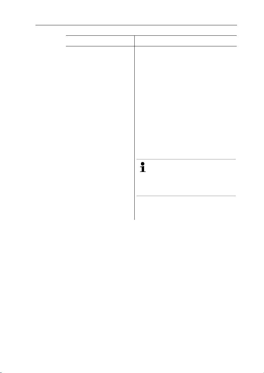
Task Actions/description
Record single images.
1. Record single image 1 (top left):
[Trigger button].
2. Rotate the camera to the right until
the image is cleanly joined to the
semi-transparent image strip of
individual image 1.
3. Record single image 2 (top centre):
[Trigger button].
4. Carry out the steps accordingly for
the other single images.
Depending on the single images
already recorded, fixed parts of the
image are shown in the left or top half
of the image. The current image must
be joined accordingly to the image on
the left or above.
When carrying out alignment to
determine where the next
single image must be joined,
the single image overview
helps, see below.
To record the single images in another
order, see single image overview
(below).
50
www.GlobalTestSupply.com
Page 51
Task Actions/description
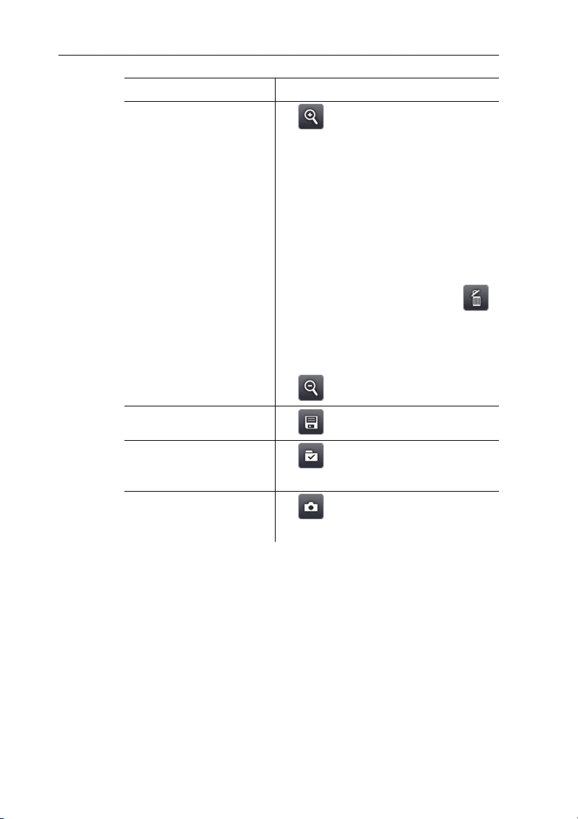
Display single image
overview and select single
image to delete/replace it.
1. .
- The single image overview is
displayed.
For a realistic display of the panoramic
image, a projection on a semi-circular
surface is required. As the image is
displayed on one plane, it is distorted
around the edges.
2. Select single image: Touch single
image. Images not available for
selection are indicated with a "X".
6 Using the product
> Delete selected single image:
.
> Replace selected single image:
Close single image overview and
record single image again.
> Close single image overview:
.
Save panoramic image.
> .
Select where to save
image.
> .
- The Folder input screen is opened.
Close image stitching
wizard.
1. .
2. Acknowledge confirmation prompt.
SiteRecognition (only testo 885-2)
With the PC software, markers can be set to clearly indicate a
measuring site. By setting a marker with the built-in digital imager,
the images, which are then saved, are automatically allocated to
the relevant site (allocation is saved with this image). For the
creation of markers, transferring of measuring site data to the
imager and copying of images to the PC software, see instruction
manual for the PC software.
51
www.GlobalTestSupply.com
Page 52
6 Using the product
Task Actions/description
Call up function.
> | | Wizards |
SiteRecognition.
- The real image is displayed and a
position frame is shown.
Once the function has been called up
via the menu (see above) and at least
one marker has be set, the function can
also be called up via the main menu
tab.
Enter measuring site
marker.
6.2.5. Configuration
Country settings
Instrument language and temperature unit can be set.
Task Actions/description
Open Country settings
input screen.
Set the language of the
program interface.
Change temperature unit.
Apply entries.
> |
.
When the imager is switched off, the
entry is removed again from the tab.
1. Position the imager so that the
marker is inside the position frame.
2. After recognition of the marker ID:
confirm transfer of measuring site
data.
> | | Configuration |
Country settings.
> Highlight the language to be used
by touching on it.
> .
- The activated unit is shown on the
top right of the display.
> .
52
www.GlobalTestSupply.com
Page 53
6 Using the product
Super-resolution (optional)
SuperResolution is a technology to improve image quality. Each
time an image is recorded, a sequence of images is saved on the
thermal imager and used to calculate a higher-resolution image
with the aid of the PC software (no interpolation). The pixel count
increases by a factor of 4, while the geometric resolution (IFOV) is
improved by a factor of 1.6.
To use the function, the imager must be hand-held (no tripod).
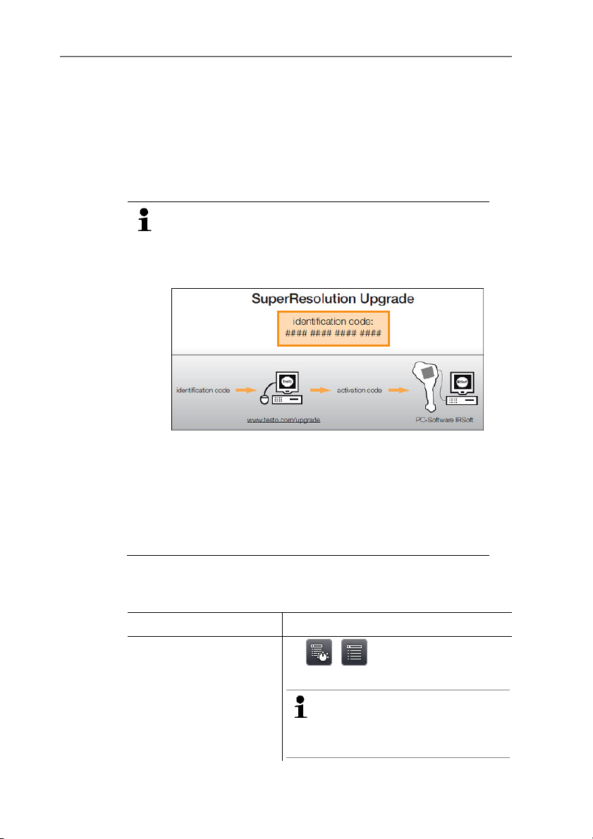
This function is available as an additional option (article
no. 0554 7806) and must be activated before it can be
used, if the option was not ordered at the same time as
the imager.
Activate function (only with subsequent order):
You will receive an envelope with an access code
(identification code), which you should enter on the
website www.testo.com/upgrade.
When all necessary data has been entered, an
activation code is generated and can be used to
activate the function via the IRSoft PC software. Please
observe the installation requirements and steps on the
website or in the email sent to you.
To use the function, the following conditions must be fulfilled:
• The imager is hand-held (no tripod).
• The objects to be imaged do not move.
Task Actions/description
Activate/deactivate
function.
>
| | Configuration |
SuperResolution.
If the function is activated,
when an image is frozen, (SR)
is displayed additionally behind
the Save Image? box.
53
www.GlobalTestSupply.com
Page 54
6 Using the product
Bluetooth (only testo 885-2)
This function is not available in all countries.
Via the Bluetooth radio interface, a link to a Bluetooth headset can
be established for voice recording. Follow the instruction manual for
the Bluetooth headset.
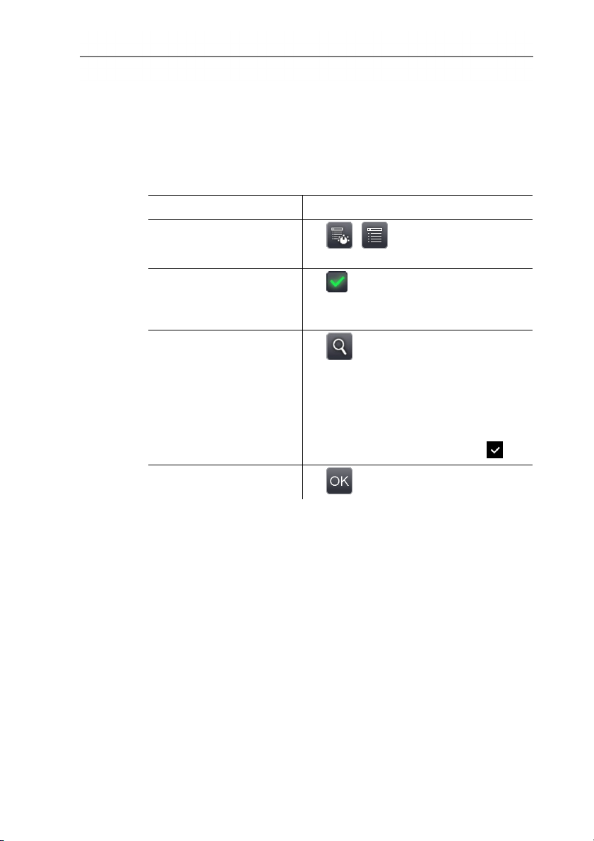
Task Actions/description
Open Bluetooth input
screen.
De-/activate Bluetooth
radio link.
Search for Bluetooth
devices and establish link.
Apply entries.
> | | Configuration |
Bluetooth.
> Active.
> To deactivate, touch the button
again.
1. .
- A search is carried out for Bluetooth
devices (with enabled pairing mode)
and available devices are
displayed.
2. Establish link to Bluetooth device:
select device by touching it ( ).
> .
54
Radio (only testo 885-2)
This function is not available in all countries.
A radio humidity probe can be logged onto the instrument.
Every radio probe has a probe identification number (RFID). This is
made up of the three-digit RFID number on the probe and the
position of the switch in the battery compartment of the radio probe
(H or L). To be logged on at the instrument, the radio probe must
be switched on and the transfer rate must be set to 0.5 s. This is
done by briefly pressing the on/off button when switching on (also
see instructions for use of radio probe).
If no radio probe is found, this may be because of the following:
• The radio probe is not switched on or the radio probe battery is
dead.
• The radio probe is outside the radio range.
• Sources of interference influence radio transmission (e.g.
reinforced concrete, metal objects, walls or other barriers
www.GlobalTestSupply.com
Page 55
6 Using the product
between the transmitter and receiver, other transmitters of the
same frequency and strong electromagnetic fields).
> If necessary: Rectify the possible causes of the fault in radio
transmission.
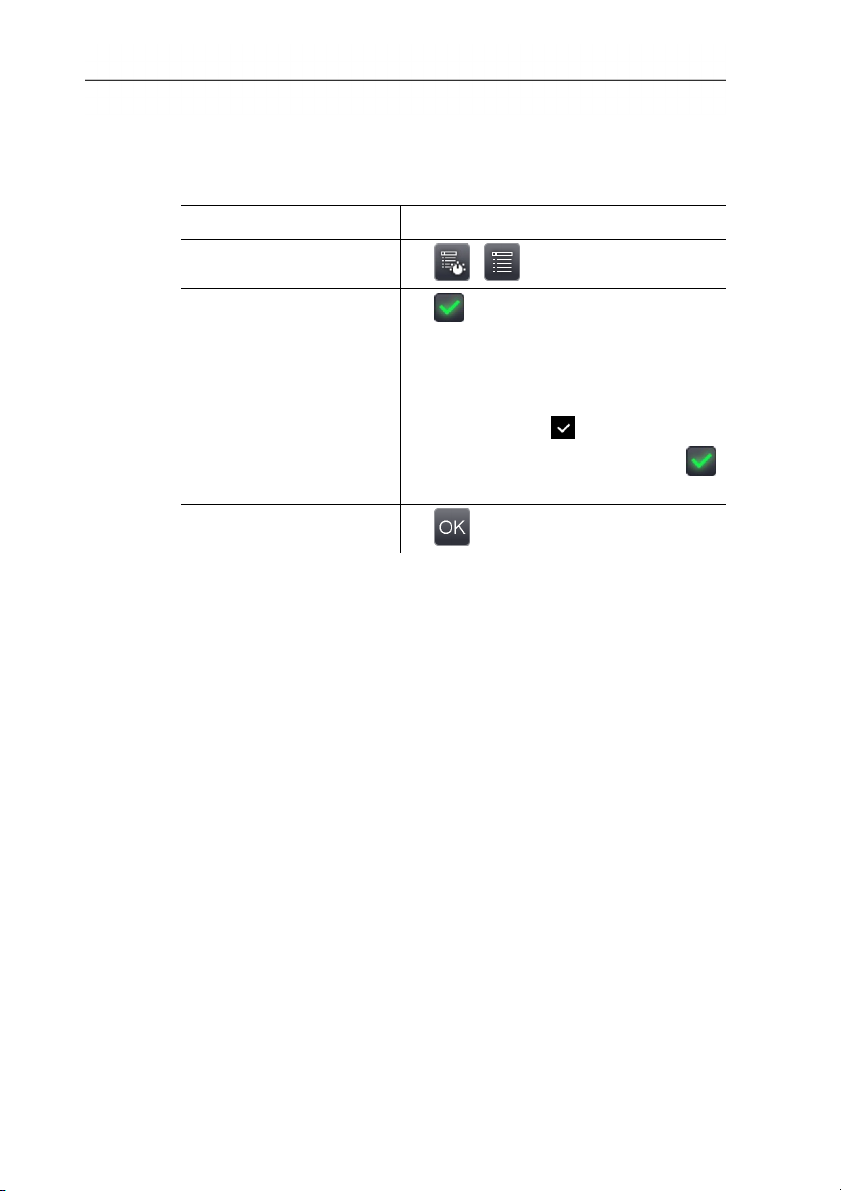
Task Actions/description
Open Radio input screen.
> | | Configuration | Radio.
Activate/deactivate radio
and establish connection
to a radio humidity probe.
1. Active.
- A search is carried out for radio
probes and available radio probes
are displayed.
2. Highlight the radio probe to be used
by touching it ( ).
> To deactivate, touch the button
again.
Apply entries.
> .
55
www.GlobalTestSupply.com
Page 56
6 Using the product
Configure key
The assignment of the shortcut keys can be changed.
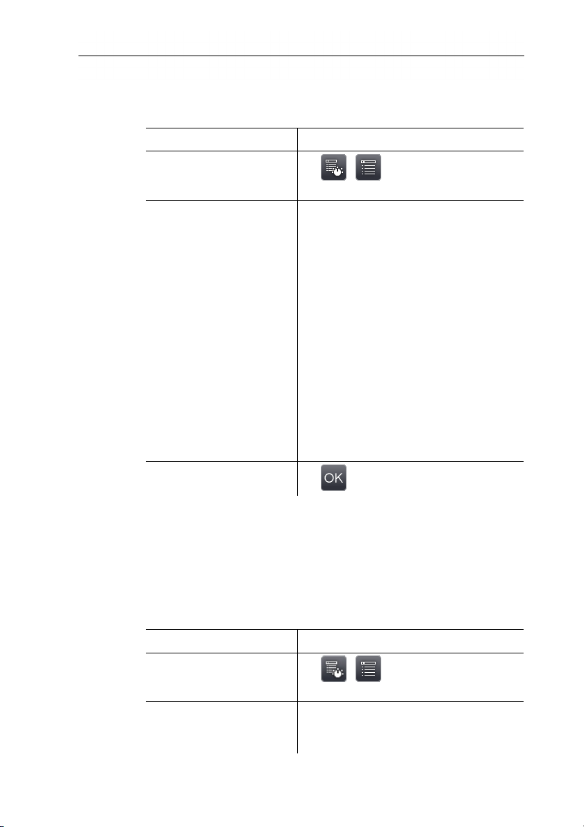
Task Actions/description
Open Configure key
input screen.
Activate button function.
Apply entries.
> | | Configuration |
Configure key.
> Highlight the function to be used by
touching on it.
The following functions can only be
activated via the shortcut keys:
• Light: switch on/off power LEDs for
lighting up objects for the digital
imager.
• Laser: switch on laser marker for
marking the measuring surface.
Operating information: the shortcut
button must be held down to
activate the laser. When the laser is
activated, an extra cursor is
displayed. This marks the precise
point at which the laser appears on
the object.
• Adjustment: Carry out adjustment.
> .
56
Optics
The lenses adjusted to the instrument are shown. Only the lenses
that are shown may be used. Lens activation is automatic (not in
USA).
The Protection glass option can be used to set whether protection
glass is fitted. Ensure the correct setting to prevent corruption of
the measurement results.
Task Actions/description
Open Optics input
screen.
> | | Configuration |
Optics.
Manually activate fitted
lens (only required in
> Highlight the lens to be used by
touching on it.
USA).
www.GlobalTestSupply.com
Page 57
6 Using the product
Task Actions/description
Activate/deactivate
protection glass option.
> Protection glass.
> To deactivate, touch the button
again.
- When the option is activated, the
protection glass symbol (
) is
displayed top right.
> To deactivate, touch the button
again.
Apply entries.
> .
Power-save options
The options affecting battery life can be set.
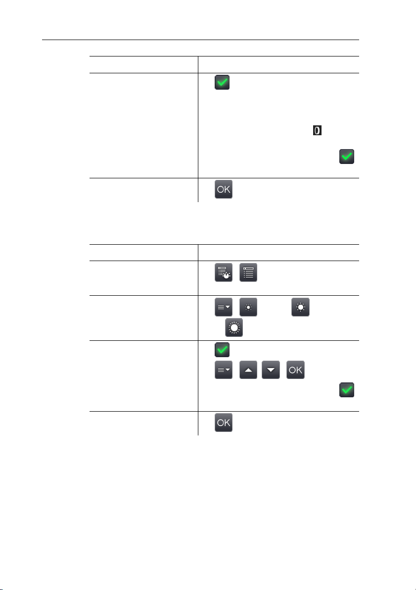
Task Actions/description
Open Power-save
options input screen.
> | | Configuration |
Power-save options.
Set the brightness of the
LCD backlight:
> | (low) or (medium)
or (high).
Activate/deactivate
automatic switch-off
function LCD off or
Imager off and set the
switch-off time.
1. Active.
2. | , | .
> To deactivate, touch the button
again.
Apply entries.
> .
Set time/date
Time and date can be set. The time and date format are set
automatically based on the selected instrument language.
57
www.GlobalTestSupply.com
Page 58

6 Using the product
Task Actions/description
Open Set time/date input
screen.
Set time or date values.
Apply entries.
Reset counter
Please note: After a reset, the consecutive numbering of images
starts again from the beginning. When saving images in the same
folder, already saved images with the same number are
overwritten!
> Back up all saved images before performing a reset to prevent
Task Actions/description
Execute function.
> | | Configuration | Set
time/date.
> .
> , .
> .
> .
possible overwriting.
1. | | Configuration | Reset
counter.
58
2. Confirm reset: .
Delete all
The data on the memory card can be deleted.
Task Actions/description
Execute function.
1. | | Configuration | Delete
all.
2. Confirm deletion: .
www.GlobalTestSupply.com
Page 59
6 Using the product
Format
The memory card can be formatted.
Please note: During formatting, all saved data on the inserted
memory card is lost.
Task Actions/description
Execute function.
1. | | Configuration |
Format.
2. Confirm format: .
Factory settings
The instrument settings can be reset to the factory settings.
Please note: time/date, country settings and counter are not reset.
Task Actions/description
Execute function.
1. | | Configuration |
Factory settings.
2. Confirm reset: .
6.2.6. Audio (only testo 885-2)
To use the function, a headset must be connected (top interface
terminal) or the link to a Bluetooth headset must be established,
see Bluetooth (only testo 885-2), Seite 54.
This function is only available with the view of a frozen or saved
image. For these images, voice commentary can be recorded and
edited.
Next to the bar display (top), two times are displayed (format
mm:ss):
• Left time: current recording or playback time (corresponds to
right end of the white recording or playback bar).
59
• Right time: maximum recording period (30 s).
Task Actions/description
Open Audio input screen.
>
| .
or
>
| | Audio.
www.GlobalTestSupply.com
Page 60
6 Using the product
Task Actions/description
Play back recording.
Start recording/resume
recording.
Stop recording/jump to
time 00:00.
Delete recording.
Set playback volume (only
for wired headset).
> .
- The recorded voice commentary is
played back from the current
playback time.
> .
- Recording is started or resumed
from the current recording time.
> .
- During recording: recording is
stopped.
- When recording is stopped:
recording or playback time is set to
00:00.
> .
1. .
60
2. (loud) or (normal) or
(quiet).
Apply entries.
> .
see Bluetooth (only testo 885-2), page 54
www.GlobalTestSupply.com
Page 61

6.3. Measuring
Important framework conditions
Please observe the following framework conditions in order to
obtain significant measurement results.
Humidity measurement:
• Pivot the separate humidity measuring instrument or optional
radio humidity probe slightly to shorten the adjustment time.
Avoid sources of interference (e.g. exhaled air).
Building thermography, investigating the building shell:
• Considerable temperature difference between inside and
outside required (ideal: >15°C / >27°F).
• Consistent weather conditions, no intensive sunlight, no
precipitation, no strong wind.
To ensure maximum accuracy, the imager requires an adjustment
time of 10 minutes after it is switched on.
Important settings
Before recording an image, check whether the protection glass
option is set correctly to prevent corruption of the measurement
results, see Optics, page 56.
Before saving an image, make sure that it is correctly focussed,
manually (see Manually focusing the image, page 29) or
automatically (see Automatically focusing the image, page 30).
Images that are not in focus cannot be corrected retroactively!
To obtain precise measurement values, the emissivity and reflected
temperature must be set correctly, see Emissivity, page 41.
Subsequent adjustment is possible via the PC software, if required.
When humidity is high or the imager is a considerable distance
from the object to be measured, atmospheric correction increases
measurement accuracy, see Atmospheric correction, page 40.
When auto-scaling is activated, the colour scale is continuously
adjusted to the min.-/max.- values of the current measurement
image. This means that the colour assigned to a specific
temperature is changing constantly! To be able to compare multiple
images based on the assigned colour, scaling must be set
manually to fixed values (see Scale manual, page 43), or must be
subsequently adjusted to uniform values using the PC software.
6 Using the product
61
www.GlobalTestSupply.com
Page 62
7 Maintaining the product
7 Maintaining the product
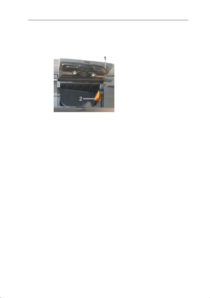
Changing the rechargeable battery
1. Open battery compartment cover (1).
2. Press red lock release button (2).
- The rechargeable battery is released and sticks out a little from
the battery compartment.
3. Pull the rechargeable battery out of the battery compartment.
4. Slide rechargeable battery fully into the battery compartment
until it clicks into place.
- The imager starts automatically.
5. Close the battery compartment cover.
Cleaning the display
> Clean the display when dirty with a cleaning cloth (e.g.
microfibre cloth).
Clean thermal imager
> If the housing of the thermal imager is dirty, clean it with a damp
cloth. Do not use any aggressive cleaning agents or solvents!
Weak household cleaning agents and soap suds may be used.
Cleaning lens protection glass
> Large dust particles can be removed with a clean optical
cleaning brush (available in specialized photography shops).
> Use a lens cleaning cloth for slight contamination. Do not use
rubbing alcohol!
62
www.GlobalTestSupply.com
Page 63

8 Tips and assistance
8.1. Questions and answers
Question Possible causes / solution
Error No memory card
inserted! is displayed.
Error Memory card full! is
displayed.
Error No lens or Wrong
lens! is displayed.
Information Charging not
possible is displayed.
Memory card defective or not inserted.
> Check or insert memory card.
Insufficient memory present.
> Insert new memory card.
> Check lens
> Change lens if necessary.
Ambient temperature is outside the
permissible range for charging the
battery.
> Observe permissible ambient
temperature.
Error Permissible
instrument temperature
exceeded! Turn off
instrument! is displayed.
--- or +++ is displayed
instead of the
measurement value.
xxx is displayed instead of
the measurement value.
1. Switch off thermal imager.
2. Allow instrument to cool down and
observe the permissible ambient
temperature.
Measurement value is outside the
measurement range.
> Change measurement range.
Reading cannot be calculated.
> Check parameter settings for
plausibility.
If we were unable to answer your question, please contact your
local dealer or Testo´s Customer Service. Refer to the back of this
document or website www.testo.com/service-contact for contact
details
8 Tips and assistance
63
www.GlobalTestSupply.com
Page 64

8 Tips and assistance
8.2. Accessories and spare parts
Description Article no.
Lens protection glass 0554 0289
Additional battery 0554 8852
Fast battery charger 0554 8851
Adhesive emission tape 0554 0051
Full radiometric video measurement (only
testo 885-2)
Super-resolution 0554 7806
ISO calibration certificates:
Calibration points at 0°C, 25°C, 50°C
Calibration points at 0°C, 100°C, 200°C
Freely selectable calibration points in the
range 18°C to 250°C
Retrofitting for high temperature
Self-adhesive labels for creating markers for
site recognition
0554 8901
0520 0489
0520 0490
0520 0495
on request from
Testo Service
available from
specialist office
supplies stockists.
Recommendation:
Avery Zweckform
L4776
64
For further accessories and spare parts, please refer to the product
catalogues and brochures or look up under www.testo.com
www.GlobalTestSupply.com
Page 65

8 Tips and assistance
65
www.GlobalTestSupply.com
Page 66

8 Tips and assistance
66
www.GlobalTestSupply.com
Page 67

www.GlobalTestSupply.com
Page 68

0970 8850 en 02 V01.00 en-GB
www.GlobalTestSupply.com
 Loading...