

Page 1
testo 816-1 Sound Level Meter
Instruction Manual
Page 2

2
Page 3

1 Contents
1 Contents
1 Contents ................................................................................................... 3
2 Safety and the environment .................................................................... 5
2.1. About this document ........................................................................ 5
2.2. Safety .............................................................................................. 5
2.3. Protecting the environment .............................................................. 6
3 Specifications .......................................................................................... 7
3.1. Use .................................................................................................. 7
3.2. Technical data ................................................................................. 7
4 Product description ............................................................................... 12
5 Using the product .................................................................................. 16
5.1. Commissioning .............................................................................. 16
5.2. Switching on / off ........................................................................... 16
5.3. Setting the date / time .................................................................... 16
5.4. Showing / hiding the date / time ..................................................... 17
5.5. Switching the display illumination on / off ...................................... 17
5.6. Changing the frequency weighting ................................................ 17
5.7. Changing the time weighting ......................................................... 17
5.8. Measuring ...................................................................................... 18
5.9. Using the min / max hold function .................................................. 19
5.10. Using individual value storage ....................................................... 20
5.11. Using measurement series storage ............................................... 20
5.12. Using AC / DC signal output .......................................................... 21
5.13. Using PC interface ......................................................................... 22
6 Maintaining the product ........................................................................ 22
6.1. Cleaning the instrument ................................................................. 22
6.2. Changing batteries ........................................................................ 22
6.3. Calibrating / adjusting the instrument ............................................ 22
7 testo 816-1 software .............................................................................. 23
7.1. System requirements ..................................................................... 23
7.2. Installing the drivers / software ...................................................... 23
7.3. Connecting the instrument to the PC ............................................. 23
7.4. Starting the software ...................................................................... 24
7.5. User interface ................................................................................ 24
7.5.1. Main menu ..................................................................................................... 24
3
Page 4

1 Contents
7.6. Real Time...................................................................................... 26
7.7. Data Logger .................................................................................. 28
8 Tips and assistance .............................................................................. 29
8.1. Questions and answers ................................................................ 29
8.2. Accessories and spare parts ......................................................... 30
4
Page 5
2 Safety and the environment
2 Safety and the environment
2.1. About this document
Use
> Please read this documentation through carefully and
familiarise yourself with the product before putting it to use. Pay
particular attention to the safety instructions and warning advice
in order to prevent injuries and damage to the product.
> Keep this document to hand so that you can refer to it when
necessary.
> Hand this documentation on to any subsequent users of the
product.
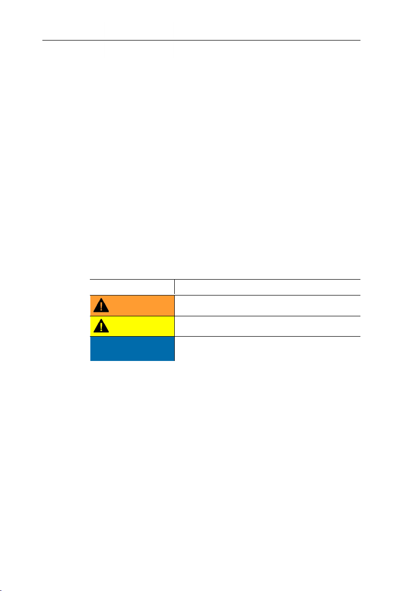
Warnings
Always pay attention to any information denoted by the following
warnings, indicated with warning pictograms. Implement the
precautionary measures specified!
Display Explanation
WARNING
Indicates possible serious injury
CAUTION
ATTENTION
2.2. Safety
Indicates possible minor injury
Indicates circumstances which may result in
damage to the product
> Only use the product properly, for the purpose it is intended for
and within the parameters specified in the technical data. Do
not apply any force.
> Do not store the product together with solvents. Do not use any
desiccants.
> Only perform maintenance and repair work on this instrument
that is described in the documentation. Follow the prescribed
steps exactly. Use only original spare parts from Testo.
> Protect the instrument from rain and humidity. Make sure that
no fluids get into the microphone.
5
Page 6

2 Safety and the environment
2.3. Protecting the environment
> Dispose of faulty rechargeable batteries / spent batteries in
accordance with the valid legal specifications.
> At the end of its useful life, send the product to the separate
collection for electric and electronic devices (observe local
regulations) or return the product to Testo for disposal.
6
Page 7
3 Specifications
3.1. Use
The testo 816-1 is a sound level meter with a measuring range of
30 to 130 dB, two time weightings, two frequency weightings,
minimum / maximum value function, individual value storage and
measurement series storage.
Measurement configurations and results are shown on the LCD
display. Measurement data can be stored in the instrument or
transferred to a Windows® PC via a PC interface.
Using the calibrator (accessory item), the meter can be adjusted
with the enclosed adjustment screwdriver.
3.2. Technical data
The instrument fulfils the requirements of IEC 61672-1 Class 2.
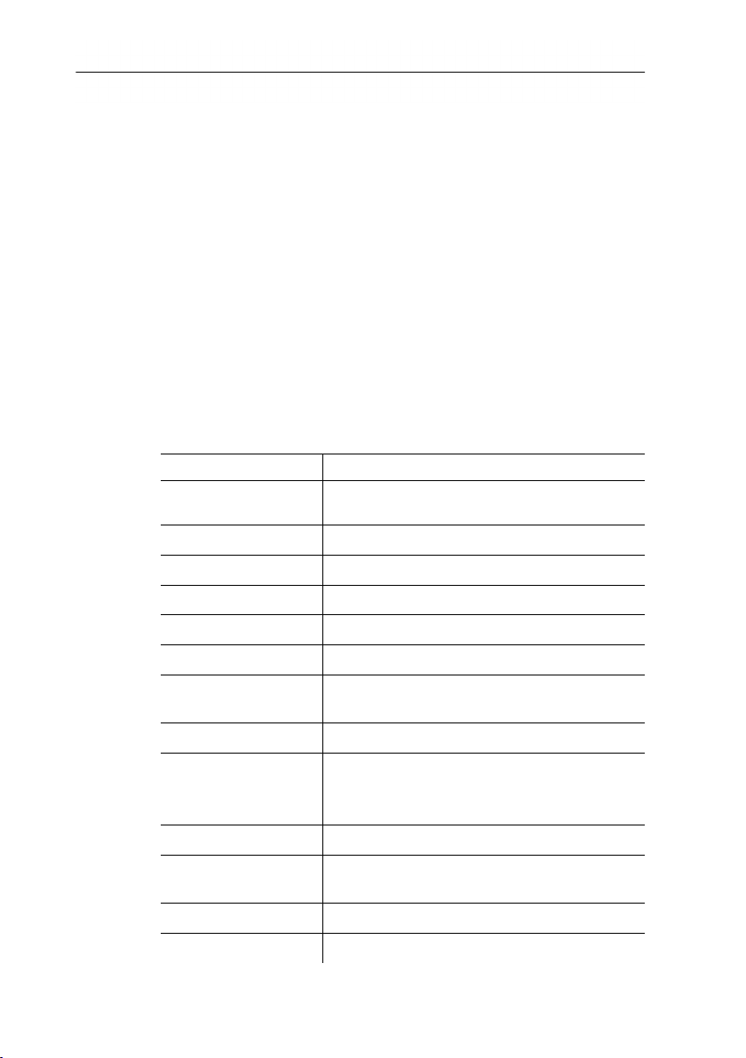
Feature Values
Microphone
Frequency range 20 Hz to 8 kHz
Measuring range 30 to 130 dB
Noise level < 30 dB
Frequency weighting A / C
Time weighting FAST (125 mS), SLOW (1 s)
Accuracy ±1.4 dB (under reference conditions
Dynamic range 100 dB
Measurement data
memory
Digital display Resolution 0.1 dB, display refresh 0.5 s
Bar graph display 50 segments, resolution 2 dB, display
AC output 1 Vrms at full deflection
DC output 10 mV / dB
3 Specifications
½-inch electret condenser measurement
microphone 2.2 kohms input impedance
@ 94 dB, 1 kHz )
Individual value memory: 99 data records
Measurement series memory: 31,000 data
records
refresh 50 mS
7
Page 8
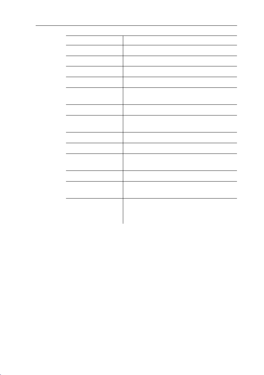
3 Specifications
Feature Values
Voltage supply 4 x IEC LR6P (AA) batteries
Battery life approx. 30 h (alkaline batteries)
Power consumption approx. 0.3 W
Mains connection 9 V DC (8-10 V DC max)
Operating
temperature
Operating humidity 10 to 90 % RH
Operating / storage
height
Storage temperature -10 to 60 °C
Storage humidity 10 to 75 % RH
Dimensions
(L x W x H)
Weight 390 g (including batteries)
Laws, guidelines,
standards
Warranty 2 years
0 to 40 °C
max. 2000m above sea level
272 × 83 × 42 mm
IEC 61672-1 Class 2, ANSI S 1.4 Type 2
Warranty terms:
see www.testo.com / warranty
8
Page 9
3 Specifications
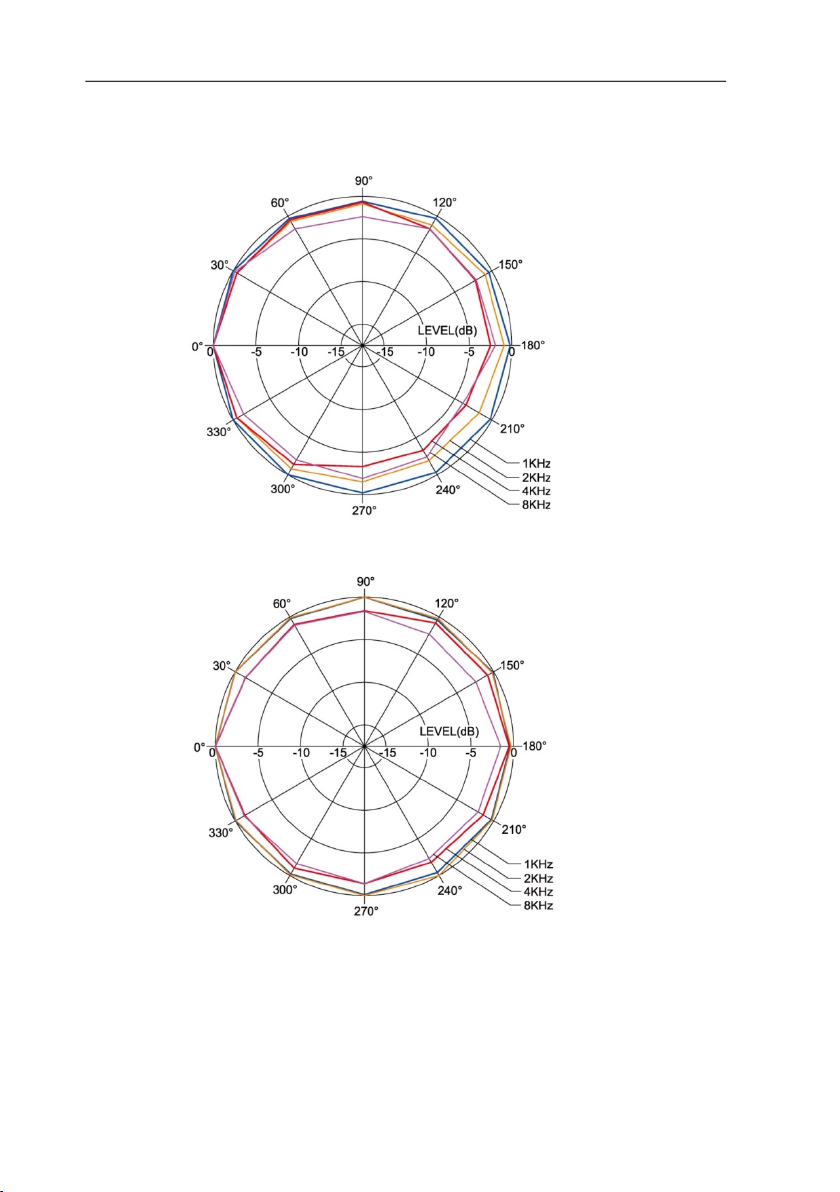
Directional characteristics of the microphone
Directional characteristics of the sound level meter
9
Page 10
3 Specifications
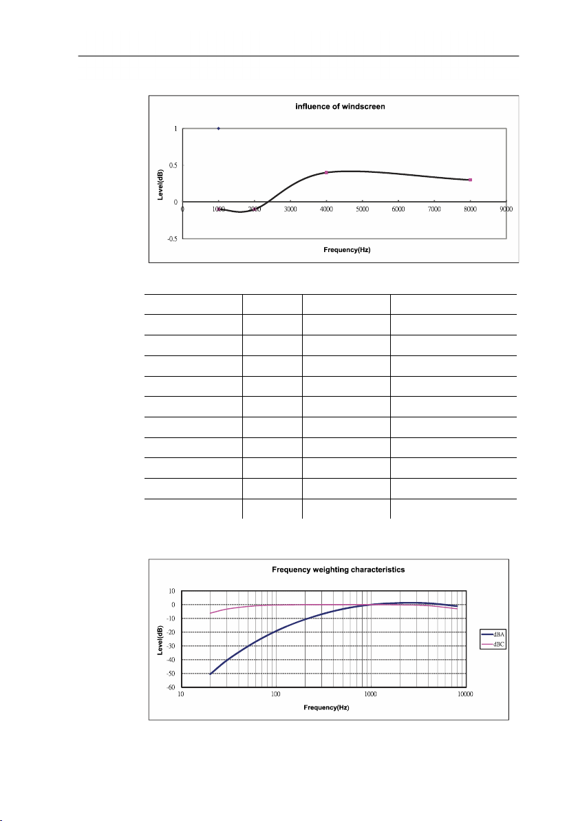
Effect of the windscreen
Frequency weighting
Frequency [Hz] dBA(dB) dBC(dB) Error limits (dB)
20 -50.5 -6.2 ±3.5
31.5 -39.4 -3.0 ±3.5
63 -26.2 -0.8 ±2,5
125 -16.1 -0.2 ±2,0
250 -8.6 0.0 ±1,9
500 -3.2 0.0 ±1,9
1000 0.0 0.0 ±1,4
2000 1.2 -0.2 ±2,6
4000 1.0 -0.8 ±3,6
8000 -1.1 -3.0 ±5,6
10
Frequency weighting characteristics
Page 11

3 Specifications
Absolute pressure dependency
Height above sea
Pressure [mbar] Offset value [dB]
level [m]
0 – 250 1013 – 984 0.0
251 – 850 983 – 915 -0.1
851 – 1450 914 – 853 -0.2
1451 – 2000 852 – 795 -0.3
Temperature dependency
Values relating to:
• Ambient humidity: 65 %RH
• Sound pressure reference value: 124 dB
• Temperature range with discrepancy < 0.5 dB: 10 to 40 °C
Temperature [°C] Offset value [dB]
-10 -0.7
0 -0.7
5 -0.6
50 +1
11
Page 12

4 Product description
4 Product description
12
Page 13

4 Product description
No. Element Description Function
1
2
3
4
5
6
7
8
9
10
11
On / Off Switch the instrument on / off
Individual value
storage data recall
Measurement series
storage
Individual value
storage
Up / down Edit view or value.
Time / date Show / hide values, edit values.
Measurement series
storage interval
Minimum /
maximum value
Display illumination Switch illumination on / off.
Frequency
weighting
Time weighting Change time weighting.
Display the stored data of an individual
value storage.
Start / stop automatic storage of
a measurement series.
Carry out manual storage of an individual
reading.
Set interval.
Display / save minimum / maximum value.
Change frequency weighting.
12 - Microphone Record readings.
13 CAL Adjustment screw Carry out adjustment.
14 PC PC interface Transfer data to PC.
15 OUTPUT AC / DC signal
Alternating / direct current signal output.
output
16 DC 9V DC-voltage input Voltage supply via external mains unit.
17 - Tripod threaded
Mount instrument onto tripod.
connection
18 - Battery
Internal voltage supply.
compartment
13
Page 14

4 Product description
Display
Element Description Function
Remaining
Remaining lifetime:
battery capacity
Fully partially discharged
Replace battery
Automatic
instrument shut-
Automatic instrument shut-down
is activated
down
Hold minimum /
maximum value
Display the minimum / maximum
value.
Time weighting Display of the time weighting
configured.
Measuring range Minimum / maximum
measurable value.
Scale display Reading display via a scale.
Individual value
storage
Time Display of time.
Individual value display is
stored.
14
Page 15

Element Description Function
Individual value
storage memory
address
Display of stored
individual value
Frequency
weighting
Reading Display of reading
Date Display of date.
Alarm for
exceeding the
measuring range
Memory full Prompt that reading memory is
Measurement
series storage
Alarm for falling
short of the
measuring range
4 Product description
Memory address of the stored
value which is displayed.
Stored individual value is
displayed.
Display of configured frequency
weighting.
Prompt due to exceeding the
maximum reading.
full.
Measurement series storage is
activated.
Prompt due to falling short of the
minimum reading.
15
Page 16

5 Using the product
5 Using the product
5.1. Commissioning
Inserting batteries
1. Remove Philips screw from the battery compartment using
a screwdriver.
2. Remove battery compartment cover.
3. Insert batteries. Observe the polarity!
4. Put cover back on the battery compartment.
5.2. Switching on / off
5. Tighten screw using a screwdriver.
Switching on (with automatic shut-down activation)
> Press the key.
- The instrument switches on and (automatic shut-down
activated) is displayed.
- The instrument switches off automatically if no key is pressed
for 30 minutes.
- The automatic shut-down is deactivated when the instrument is
connected to a PC or when automatic data recording is in
process.
Switching on (without automatic shut-down activation)
1. Hold down the key and press the key.
2. Hold down the key until the instrument switches on.
- The instrument switches on. is not displayed.
Switching off
> Hold the key down until P-OFF is displayed.
5.3. Setting the date / time
The integrated clock enables readings to be stored with the date
and time.
1. Hold down the key for 2 s.
The values are set in the following order: (year), (month), (day),
(hour), (minute), (second).
16
Page 17

5 Using the product
s from one reading per second to
2. Press the or key to set a value, press the key to
change to the next value.
> Press the key to cancel the process.
5.4. Showing / hiding the date / time
> Press the key.
5.5. Switching the display illumination on / off
Switching on / off manually
> Press the key.
Automatic switch-off
The display illumination is switched off automatically after 30 s.
5.6. Changing the frequency weighting
Frequency weighting A is used for standard sound level
measurements. This weighting corresponds to the
perception of sound by the human ear. “Aurally
compensated” volume is referred to in this context.
If the low-frequency portions of a sound are also to be
weighted, frequency weighting C is used. If the displayed
C-weighting value is considerably higher than the Aweighting value, then there is a large amount of lowfrequency noise.
> Press the key.
5.7. Changing the time weighting
The ranges “Slow”, with a time weighting of 1s, and “Fast”,
with a time weighting of 125ms, are available. The incoming
sound signals are incorporated over a period of 1 s or 125 ms
accordingly. If “Fast” is set, the rate at which readings are
shown in the display increase
around 5 - 6 readings per second. The “Slow” time weighting
should be selected for noises whose signals only change in
volume gradually, such as machines, photocopiers, printers
etc. Select the “Fast” mode to measure sudden changes in
17
sound level (e.g. building machinery).
> Press the key.
Page 18

5 Using the product
5.8. Measuring
Information and recommendations
• Sound waves can be reflected off walls, ceilings and other
objects. If not handled correctly, the measuring instrument
housing and the person conducting the measurement are also
disruptive factors within the sound field and can result in
incorrect measurement results.
• Not only can the instrument housing and the person operating
the instrument impede the sound which comes from a particular
direction, they may even cause reflections, resulting in
significant measurement errors. Experiments have shown, for
example, that at frequencies around 400 Hz the body can
cause errors of up to 6 dB if a measurement is carried out less
than one meter away from the person. This error is smaller at
other frequencies, but a minimum distance should still be
observed. Generally, it is recommended that the measuring
instrument is held at least 30 cm - even better 50 cm - away
from the body.
• We recommend fitting the instrument to a tripod for exact
measurements
• Absolute pressure dependency: The measuring instrument is
calibrated at a height of 0 m above sea level in the factory.
Measurements at other heights give rise to measurement errors
which can be corrected using a table (see technical data).
Please subtract the corresponding offset value from the
measured value (e.g. - 0.1 dB for measurements at a height of
500 m above sea level). Prevent this measuring error by
adjusting the measuring instrument at the corresponding height
before (and after) each measurement. Follow the instruction
manual for the calibrator.
• Windscreen: The windscreen included in the delivery should
generally be set up for measurements outdoors or if the air is
moving. Wind noises around the microphone will cause a
measuring error as the useful signal (from the noise source)
and the wind noise will be added together.
The windscreen will not distort the reading.
• Overmodulation and undermodulation: With every
measurement cycle, the sound level meter checks whether the
measured sound level is within the scope of the measuring
range. Deviations are indicated by “Over” or “Under” on the
display. However, the criteria for overmodulation and
undermodulation are different. Overmodulation is signalled if
the maximum value (peak value e.g. short sound pulse, bang)
during the last measurement cycle was too high. This value
18
Page 19

may be considerably higher than the actual value of the sound
level displayed. Therefore, “Over” may be signalled despite the
fact that a sound level within the normal framework of the
respective measurement range is shown. By contrast “Under” is
geared to the measured actual value and is therefore set when
the lower limit of the measurement range is undershot.
Carrying out a measurement
1. Switch the instrument on.
2. Set the measuring time (FAST / SLOW)
3. Set the frequency (A / C)
4. Always aim the microphone directly at the sound source to be
measured (reference direction).
5.9. Using the min / max hold function
Holding readings
> Press the key.
- lights up. The maximum value since the function was
activated is displayed and held automatically.
> Press the key again.
- lights up. The minimum value since the function was
activated is displayed and held automatically.
5 Using the product
> Press the key again.
- and flash. The current measurement value is
shown. The minimum value and maximum value since the
function was activated are automatically held.
> Press the key again.
- The hold function is deactivated.
Resetting the hold function
> Hold down the key for two seconds.
The recorded values are deleted.
19
Page 20

5 Using the product
5.10. Using individual value storage
Storing an individual value
> Press the key.
- lights up briefly and the individual value is stored under
the next available memory address.
Displaying a stored individual value
> Press the key.
- lights up. The individual value of the most recent
individual value storage and the memory address are displayed.
> Switch between individual memory addresses using the and
keys.
- If memory addresses have not yet been allocated, 00 is
displayed instead of the reading.
Deleting an individual value memory
1. Switch the instrument off.
2. Hold down the key and the key.
- While the keys are held down: CLr is displayed, SURE flashes
and a countdown (5 seconds) starts.
3. Once the countdown is complete, release the keys.
- The memory is deleted.
5.11. Using measurement series storage
Setting the storage interval
1. Press the key.
2. Use the and keys to set the interval (in seconds)
(minimum: 1 second, maximum 1 minute).
3. Press the key again.
20
Page 21

5 Using the product
DC Signal
AC Signal
Ground
Saving a measurement series
When measurement series storage is activated, most functions
(individual value storage, storage interval setting, frequency
weighting, time weighting) are deactivated.
1. Press the key.
- lights up and the readings are stored.
2. Press the key again.
- The storage of readings is completed.
Deleting a measurement series memory
1. Switch the instrument off.
2. Hold down the key and the key.
- While the keys are held down: CLr is displayed, SURE flashes
and a countdown (5 seconds) starts.
3. Once the countdown is complete, release the keys.
- The memory is deleted.
Displaying a measurement series
Stored measurement series are displayed and evaluated via the
PC software, see 7.7 Data Logger, page 28.
5.12. Using AC / DC signal output
Specifications
AC: 1 Vrms at full deflection, output impedance approx. 100 ohms,
output signal via standard 3.5mm jack plug (see illustration below).
DC: Output 10mV / dB, output impedance 1 kohm, output signal via
standard 3.5mm jack plug (see illustration below).
21
Page 22

6 Maintaining the product
5.13. Using PC interface
The RS232 / USB connecting cable is required in order to use the PC
interface. Signal output specification: Serial interface, 9600 bps N 8 1.
6 Maintaining the product
6.1. Cleaning the instrument
> Wipe the instrument housing regularly with a dry cloth. Do not
use any abrasives or solvents.
6.2. Changing batteries
Change the batteries within 30 minutes. Following any
longer interruption in operation and battery removal, the
6.3. Calibrating / adjusting the instrument
date and time need to be reset.
1. Remove Philips screw from the battery compartment using
a screwdriver.
2. Remove battery compartment cover.
3. Remove spent batteries and replace with new ones. Observe
the polarity!
4. Put cover back on the battery compartment.
5. Tighten screw using a screwdriver.
The recommended calibration interval is one year.
The sound calibrator 0554 0452 is required for calibration /
adjustment. To carry this out, please observe the instruction
manual supplied with the sound calibrator.
The measuring instrument has already been calibrated in the
factory. However, to check the accuracy it is recommended,
particularly if the instrument has not been used for a long time, to
calibrate the instrument using the calibrator.
For measurements in harsh conditions, at high altitudes, in high
humidity or where there are particularly stringent requirements for
the measurement results, the instrument should be checked with
the calibrator before and after the measurement.
22
Page 23

To calibrate, the calibrator is screwed onto the microphone. Switch
the sound level meter on and set the time weighting to “Fast” and
the frequency weighting to “A”.
The calibrator is then switched on by moving the switch to the
middle setting (94 dB). If there is a discrepancy in the displayed
value, you can adjust the sound level meter using the screwdriver
included.
It is then possible to check whether the second level shown by the
calibrator is within the ± 0.2 dB margin of error. If the value shown
is not within the margin of error, please contact our service team.
7 testo 816-1 software
7.1. System requirements
• PC with Windows® operating system
• The computer must meet the requirements of the corresponding
operating system. The following requirement must also be met:
50 MB disk space for installing the software
7 testo 816-1 software
7.2. Installing the drivers / software
1. Insert the program CD into the CD-ROM drive of the computer.
If the installation program does not start automatically:
> Open My Computer, select the CD drive and start the
MainSetup.exe file.
2. Follow the instructions of the installation wizard.
- The required device driver is installed first, followed by the
software.
7.3. Connecting the instrument to the PC
1. Connect the RS232 / USB connecting cable to the instrument
and the PC.
2. Switch the instrument on: Press the key.
23
Page 24

7 testo 816-1 software
7.4. Starting the software
The software's user interface is only available in English
1. Connect the instrument to the PC before starting the software.
2. Click on (Start) | (All) Programs | t816-1 | t816-1.
7.5. User interface
7.5.1. Main menu
File
Function Description
Open
Save
Printer
Printer Setup
Exit
24
Open files.
Save data (current view).
Print data (current view).
Select and set up printer.
Close program.
Page 25

7 testo 816-1 software
Real Time
Function Description
Run
Stop
Start real-time measurement.
End real-time measurement.
Data Logger
Function Description
Load Data Load measurement series from the
instrument memory into the software.
Erase Memory Delete measurement series stored in the
instrument memory.
RECALLl
Function Description
RECALL Display individual readings from the
instrument memory.
View
Function Description
Control Panel
Real-Time
Graph
Display the meter control window.
Display window for real-time display of the
current readings.
Window
Function Description
Tile
Cascade
Arrange windows one above another.
Freely arrange windows.
Help
Function Description
Contents
Info
Open help file.
Display program information.
25
Page 26

7 testo 816-1 software
7.6. Real Time
Function for the real-time display of instrument readings.
Making settings
Function Description
Real-Time data
no. to be
recorded
Real-Time
sampling rate
Recording
Period
Start
Input field: enter the number of readings that
are to be recorded.
Input field: enter the recording rate.
Information field: calculated recording period
is displayed.
Start real-time display
26
Real-Time Graph
Page 27

Function bar
Function Description
Show / hide bar for displaying the recording
information.
Show / hide bar for displaying the evaluation
information.
Standard mouse cursor.
7 testo 816-1 software
graph.
Mouse cursor for inserting a comment in the
Mouse cursor for inserting a cross in the
graph.
Zoom
1. Activate standard mouse cursor.
2. Click in the graph and draw a rectangle by holding down and
dragging your mouse.
- The selected graph area is displayed.
3. To return to the standard view, press the button.
Displaying individual readings / evaluating the time period
The bar for displaying the evaluation information ( ) must be
shown.
> Move both slide controls (green) below the graph.
- A blue line (cursor A) and a red line (cursor B) are displayed
together with reading and time at the selected position.
- Maximum / minimum reading and time are displayed in the
selected area A-B.
- The average reading is displayed in the selected area A-B.
Adjusting graph properties
> Press the button.
- A window opens for adjusting the graph settings.
Exporting recorded readings
1. Press the button.
- The readings are copied to the clipboard.
2. Open program into which the data is to be exported
(e.g. Microsoft® Excel®) and paste in data.
27
Page 28

7 testo 816-1 software
Saving recorded readings
1. In the main menu, select the File | Save function.
- Windows dialogue box for saving files is opened.
2. Enter a file name and select a file format.
In order to be able to display the data later in the software, select
the file type .ghf. If the data is to be exported for use in some other
software, select the file type .txt
3. Select the location you want to save it to and click on [Save].
7.7. Data Logger
Function for displaying measurement series from the instrument
memory.
28
The measurement series available in the instrument memory are
displayed on the left-hand side and can be selected by clicking on
them with the mouse.
On the right-hand side the selected measurement series is displayed.
The functions for displaying and evaluating the measurement data
correspond to those for Real Time (see above section).
In addition to the functions described there, it is possible to save all
measurement series (data sets) available in the instrument
memory. In order to do this, the .rec data format must be selected
in the Windows dialogue box for saving files.
Page 29

8 Tips and assistance
8.1. Questions and answers
Question Possible causes / solution
The sound level meter was
connected to the PC, but NO
CONNECTION is displayed in
the software.
How do you transfer readings
It is possible that all the ports are
assigned to other applications.
> Close all other applications.
> Restart PC and software.
> Save data as a comma-
to spreadsheet software?
How do you uninstall the
> Open the Control Panel in the
software?
Real Time function: when
there is a short measuring
PC's response times are too long.
> Extend the measuring cycle.
cycle (e.g. 0.1 s), not all
readings are transferred.
If we have not been able to answer your question, please contact
your dealer or Testo Customer Service. For contact details, see the
back of this document or visit the website www.testo.com / servicecontact.
8 Tips and assistance
separated text file (*.txt).
operating system and open the
function for uninstalling
programs.
29
Page 30

8 Tips and assistance
8.2. Accessories and spare parts
Description Item no.
Calibrator 0554 0452
Windscreen
RS232 / USB connecting cable
ISO calibration certificate sound pressure;
calibration point 94 dB, at different frequencies
ISO calibration certificate sound pressure
calibrators
For a complete list of all accessories and spare parts, please refer
to the product catalogues and brochures or visit our website
www.testo.com
Please contact
the Service
department
Please contact
the Service
department
0520 0111
0520 0411
30
Page 31

Page 32

0970 8161 en 01
 Loading...