

Page 1
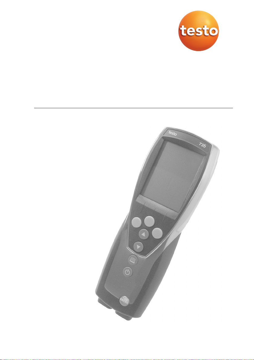
testo 735
Temperature measuring instrument
Instruction manual en
Contents
General notes ......................................................2
1. Safety instructions................................................4
2. Intended purpose ................................................5
3. Product description..............................................6
3.1 Display and control elements ..........................................6
3.2 Interfaces ........................................................................8
3.3 Voltage supply ................................................................8
4. Commissioning ....................................................9
5. Operation ..........................................................10
5.1 Connecting a probe ......................................................10
5.2 Switching on/off ............................................................10
5.3 Display light ..................................................................11
6. Setting the instrument ........................................12
6.1 Configuration menu ......................................................12
6.1.1 Profile..............................................................................12
6.1.2 Units ..............................................................................13
6.1.3 Device ............................................................................13
6.1.4 Probe ..............................................................................15
6.1.5 Language ........................................................................16
6.2 Main menu ....................................................................17
6.2.1 Memory (735-2 only) ......................................................18
6.2.2 Measuring program (735-2 only) ....................................19
6.2.3 Mean ..............................................................................20
6.2.5 Alarm ..............................................................................20
7. Measuring ..........................................................22
8. Care and maintenance ......................................24
9. Questions and answers......................................25
10. Technical data ....................................................26
11. Accessories / spare parts ..................................27
Page 2
2
General notes
This chapter provides important advice on using this documentation.
The documentation contains information that must be applied if the product is
to be used safely and efficiently.
Please read this documentation through carefully and familiarise yourself with
the operation of the product before putting it to use. Keep this document to
hand so that you can refer to it when necessary.
Identification
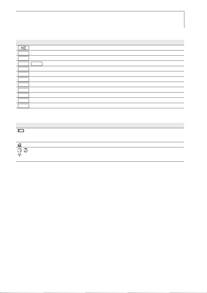
Representation Meaning Comments
Warning advice: Warning! Read warning advice carefully and take the precautionary measures
indicated! Serious physical injury could occur if you do not take the
precautionary measures indicated.
Warning advice: Caution! Read warning advice carefully and take the precautionary measures
indicated! Slight physical injury or damage to equipment could occur
if you do not take the precautionary measures indicated.
Note Offers helpful tips and information.
➢, 1, 2 Objective Denotes the objective that is to be achieved via the steps described.
Where steps are numbered, you must always follow the order given!
✓ Condition A condition that must be met if an action is to be carried out as
described.
, 1, 2, ... Step Carry out steps. Where steps are numbered, you must always follow
the order given!
Tex t Display text Text appears on the instrument display.
Control button Press the button.
Function button Press the button.
- Result Denotes the result of a previous step.
➫ Cross-reference Refers to more extensive or detailed information.
Button
General notes
Page 3
3
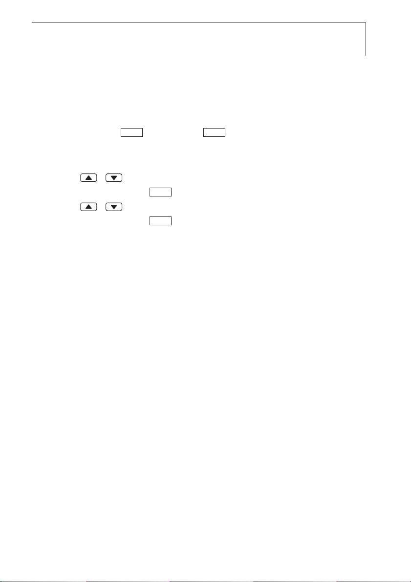
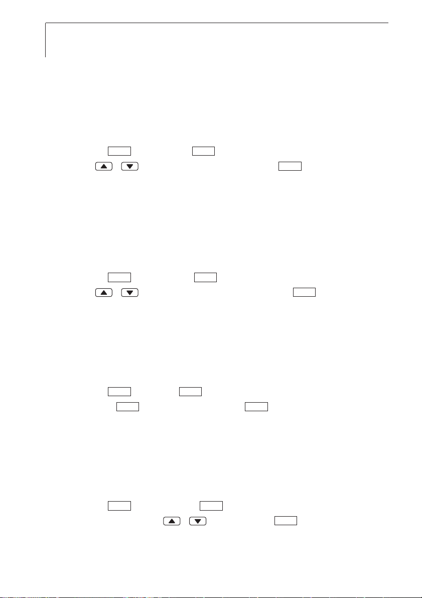
Short form
This document uses a short form for describing operating steps (e.g. calling up
a function).
Example: Calling up the “Instrument data” function
Short form: Device ➝➝Inst.data ➝ .
(
1) (2) (3) (4)
Steps required:
1 Press / to select the Device function.
2 Confirm selection with .
3 Press / to select the Inst.data function.
4 Confirm selection with .
OK OK
OK
OK
defresitptsvnl????
General notes
Page 4

4
1. Safety instructions
This chapter gives general rules which must be followed and observed if the
product is to be handled safely.
Avoid personal injury/damage to equipment
Do not use the measuring instrument and probes to measure on or near live
parts.
Never store the measuring instrument/measuring cells together with solvents
and do not use any desiccants.
Product safety/preserving warranty claims
Operate the measuring instrument only within the parameters specified in the
Technical data.
Always use the measuring instrument properly and for its intended purpose.
Do not use force.
Do not expose handles and feed lines to temperatures in excess of 70 °C
unless they are expressly permitted for higher temperatures. Temperatures
given on probes relate only to the measuring range of the sensors.
Open the instrument only when this is expressly described in the
documentation for maintenance or repair purposes.
Carry out only the maintenance and repair work that is described in the
documentation. Follow the prescribed steps when doing so. For safety
reasons, use only original spare parts from Testo.
Ensure correct disposal
Take faulty rechargeable batteries/spent batteries to the collection points
provided for them.
Send the product back to Testo at the end of its useful life. We will ensure
that it is disposed of in an environmentally friendly manner.
1. Safety instructions
Page 5

5
defresitptsvnl????
Instruments with radio module 915.00MHz FSK
Warning: Changes or modifications not expressly approved by the party responsible for compliance could void
the user's authority to operate the equipment.
This equipment has been tested and found to comply with the limits for a Class B digital device, pursuant to Part
15 of the FCC Rules.
These limits are designed to provide reasonable protection against harmful interference in a residential installation.
This equipment generates, uses and can radiate radio frequency energy and, if not installed and used in
accordance with the instructions, may cause harmful interference to radio communications.
However, there is no guarantee that interference will not occur in a particular installation. If this equipment does
cause harmful interference to radio or television reception, which can be determined by turning the equipment off
and on, the user is encouraged to try to correct the interference by one or more of the following measures:
· Reorient or relocate the receiving antenna.
· Increase the separation between the equipment and receiver.
· Connect the equipment into an outlet on a circuit different from that to which the receiver is needed.
· Consult the dealer or an experienced radio/TV technician for help.
Operation is subject to the following two conditions:
· this device may not cause harmful interference, and
· this device must accept any interference received, including interference that may cause undesired operation.
2. Intended purpose
This chapter gives the areas of application for which the product is intended.
Use the product only for those applications for which it was designed. Ask
Testo if you are in any doubt.
testo 735 is a compact measuring instrument for measuring temperature.
The product was designed for the following tasks/applications:
· Food industry
· Use as a reference standard with high-precision Pt100
immersion/penetration probes
The product should not be used in the following areas:
· Areas at risk of explosion.
· Diagnostic measurements for medical purposes.
1. Safety instructions
Page 6
6
3. Product description
This chapter provides an overview of the components of the product and their
functions.
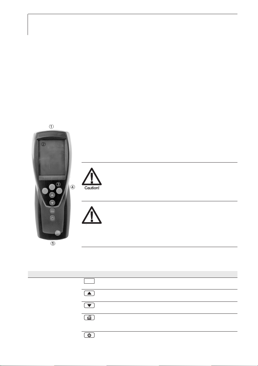
3.1 Display and control elements
Overview
➀ Infrared, USB interface
➁ Display (light can be activated)
➂ Control buttons
➃ Rear: Battery and radio module compartment, holding
magnets
Magnetic field
May be harmful to those with pacemakers!
Keep a minimum distance of 15 cm between
pacemaker and instrument.
Magnetic field
Damage to other instruments!
Keep a safe distance from products which
could be damaged by magnetism (e.g.
monitors, computers, credit cards).
➄ Probe socket(s)
Button functions
Button Functions
Function button (3x): The function depends on the button assignment
at the time
Change display of the 1streading line
In configuration mode: Increase value, select option
Change display of the 2ndreading line
In configuration mode: Decrease value, select option
Print data
735-1 only: If the Cyclical Printing function is activated, the
programmed measuring program is started.
Switch instrument on, switch display light on/off;
switch instrument off (press and hold)
3. Product description
Page 7
7
defresitptsvnl????
Function buttons (Function dependant on profile and setting)
Button Functions
Open (main) menu
Enter confirmation
Cancel
/ Hold value/display current measurement value
Reset max./min. values to current measurement value
Open menu item “Multi-point mean calculation“
Open menu item “Measuring program” (735-2 only)
Start test series (735-2 only)
End test series (735-2 only), End Cyclical Print (735-1 only)
Save values (735-2 only)
Open menu item “RadioC“
Open menu item“Location“
Important displays
Display Meaning
Battery capacity (only for operation by battery/rechargeable battery):
· 4 segments in the battery symbol are lit: Instrument battery is fully charged
· No segments in the battery symbol are lit: Instrument battery is almost spent
(flashing) Print function: Data are sent to the printer
, Measurement channel no.: Channel 1, channel 2.
If a measurement channel is a radio channel, the radio symbol lights up as well as the
measurement channel no.
MEM
Radio
Save
End
Start
Measp
Mean
Reset
Hold ACT
ESC
OK
3. Product description
Page 8

8
3.2 Interfaces
Infrared interface
Measurement data can be sent to a Testo printer via the infrared interface on
the head of the instrument.
USB interface
The mains unit (accessory part) can be connected to the head of the
instrument via the USB interface to power the instrument.
Instruments with a memory: Measurement/instrument data can be exchanged
with a PC via the USB interface.
Probe socket(s)
Plug-in measuring probes can be connected via the probe socket(s) on the
base of the instrument. The instrument is a HighPower device, possibly an
additional USB-Hub is required!
Radio module (accessory part)
Radio probes may only be used in countries in which they have been Type
Approved (see application infor mation of the radio probe).
Up to three radio probes can be connected via the radio module.
3.3 Voltage supply
Voltage is supplied via three mignon batteries (included in delivery) or
rechargeable batteries or through a mains unit (accessory part). It is not
possible to charge rechargeable batteries in the instrument.
When operating the instrument with the mains unit, insert batteries in order
to avoid switching off the instrument in case of a power interruption.
3. Product description
Page 9

9
defresitptsvnl????
4. Commissioning
This chapter describes the steps required to commission the product.
➣
Inserting batteries/rechargeable batteries and a radio module (accessory
part):
1 Undo the two screws on the rear of the instrument and lift off the battery
compartment cover.
2 Insert batteries/rechargeable batteries (3x mignon) into the battery
compartment. Observe the polarity!
3 Push the radio module (accessory part) into the radio module
compartment until it engages in place. Note the guide groove.
4 Replace the battery compartment cover, press down and secure by
tightening the two screws.
4. Commissioning
Page 10

10
5. Operation
This chapter describes the steps that are executed frequently when using the
product.
5.1 Connecting a probe
Plug-in probes
Plug-in probes must be connected before the measuring instrument is
switched on so that they are recognised by the instrument.
Insert the connector of the probe into the probe socket of the measuring
instrument.
Radio probes
Radio probes may only be used in countries in which they have been Type
Approved (see application infor mation of the radio probe).
A radio module (accessory part) is required for the use of radio probes. The
radio module must be connected before the measuring instrument is switched
on so that it is recognised by the measuring instrument.
Each radio probe has a probe ID (identification number) which must be set in
configuration mode.
➫ See chapter PROBE, p. 15.
5.2 Switching on/off
➣
Switching the instrument on:
Press .
- Only 735-2: If probe adjustment data are stored in the instrument and
activated, Adjustm. active appears in the display (duration: 2s).
➫ See chapter PROBE, p. 15.
- Measurement view is opened: The current reading is displayed, or
---- lights up if no reading is available.
Instruments with a memory: The activated location is displayed
(topmost line).
-or-
5. Operation
Page 11

11
defresitptsvnl????
The instrument is switched on for the first time, a reset was carried out or
the power supply was interrupted for a lengthy period of time:
- The Language function is opened.
➫ See the chapter LANGUAGE, p. 16.
➣
Switching the instrument off:
Press and hold (for approx. 2s) until the display goes out.
5.3 Display light
➣
Switching the display light on/off:
✓ The instrument is switched on.
Press .
5. Operation
Page 12

12
6. Setting the instrument
This chapter describes the steps that are required in order to adapt the
measuring instrument for specific measuring tasks.
6.1 Configuration menu
The basic settings for the measuring instrument are performed in the
configuration menu.
➣
Opening the configuration menu:
✓ The instrument is in measurement view.
Press and hold (approx. 2s) until config. is displayed.
Press to go one menu level back. To leave the configuration menu,
press several times until the instrument changes to measurement view.
6.1.1 Profile
The instrument has predefined measurement profiles that are tailored to
specific areas of application.
The profile setting influences the following points in measurement mode:
· Assignment of the function buttons
· Number of predefined functions
· Structure of the main menu
All functions are available in the standard profile. In the application-specific
measurement profiles, the available functions are reduced to only those that are
needed to ensure speedier access.
➣
Setting a profile:
✓ The configuration menu is open, config. is displayed.
1 Profile ➝ .
2 Select the desired profile with / and confirm with .
ESC
ESC
OK
OK
6. Setting the instrument
Page 13

13
defresitptsvnl????
6.1.2 Units
Predefined systems and individual setting options:
Parameter ISO system US system Individual setting options
Temperature °C °F °C, °F
➣
Setting units:
✓ The configuration menu is open, config. is displayed.
1 Units ➝ .
2 Press / ISO/US (to set the system) or a parameter (to set
individually) and confirm with .
3 Set the system of units or the desired unit with / and confirm
with .
6.1.3 Device
Instrument data
➣
Displaying instrument data:
✓ The configuration menu is open, config. is displayed.
1 Device ➝➝Inst.data ➝ .
- The firmware version and the serial number of the instrument are
displayed.
Date / Time
➣
Setting the date/time:
✓ The configuration menu is open, config. is displayed.
1 Device ➝➝date/time ➝ .
2 Use / to set the value for year and confirm with .
3 Set the other values as described in step 2.
OK
OK
OK
OK OK
OK OK
OK
6. Setting the instrument
Page 14
14
Battery type
To ensure that the battery capacity is displayed correctly, the battery type used
must be set.
➣
Setting the battery type:
✓ The configuration menu is open, config. is displayed.
1 Device ➝➝Bat-type ➝ .
2 Press / Battery or ReBa and confirm with .
Auto OFF
If Auto OFF is switched on, the instrument switches itself off automatically after
10min if no button is pressed. Exception: Cyclical printing (instruments without
a memory) or a measuring program (instruments with a memory) is active.
➣
Switching Auto OFF on/off:
✓ The configuration menu is open, config. is displayed.
1 Device ➝➝Auto OFF ➝ .
2 Press / to select On or Off and confirm with .
Reset
When a reset is carried out, the instrument is reset to the default settings, all
settings/ data are deleted. Exception: Language, Date/ Time.
➣
Resetting:
✓ The configuration menu is open, config. is displayed.
1 Device ➝➝reset ➝ .
2 Reset with or cancel the reset with .
Setting min. / max. printing function
If pr MinMaxAuto is activated, minimum and maximum values are also printed
with the measurement readings.
➣
Switching off pr MinMax:
✓ The configuration menu is open, Config. is displayed.
1 Device ➝➝pr MinMax ➝ .
2 Choose On or Off with / and confirm with .
OK
OKOK
OK
OK OK
OK
OK OK
OK ESC
OKOK
6. Setting the instrument
Page 15

15
defresitptsvnl????
6.1.4 Probe
RadioC
Radio probes may only be used in countries in which they have been Type
Approved (see application infor mation of the radio probe).
A radio module (accessory part) is required for the use of radio probes. The
instrument can establish a connection with a maximum of three radio probes.
Each radio probe has a probe ID (RF ID). This consists of the last 3 digits of the
serial no. and the position of the slide switch (H or L) in the radio probe.
➣
Setting up a radio probe:
✓ A radio module (accessory part) is inserted in the instrument.
➫ See chapter COMMISSIONING, p. 9.
✓ The configuration menu is open, config. is displayed.
✓ The radio probe is switched on and the transfer rate is set to 2 readings
per second (see the advice on using the radio probe).
1 Probe ➝➝RadioC ➝ .
2 Press / to select the desired channel no. for the radio probe (P. 1 ,
P. 2 or P. 3 ) and confirm with .
- The instrument searches for switched-on radio probes in the receiving
range.
- The probe IDs of the radio probes found are displayed.
If no radio probes were found, this may be because of the following:
· The radio probe is not switched on or the battery of the radio probe is
spent.
· The radio probe is outside the range of the measuring instrument.
· Sources of interference are influencing the radio transmission (e.g.
reinforced concrete, metal objects, walls or other barriers between
transmitter and receiver, other transmitters of the same frequency,
strong electromagnetic fields).
If necessary, rectify the possible causes of the fault in radio
transmission.
Alternatively, the probe ID can also be entered manually.
➝ Press / to enter the probe ID.
MAN
OK
OK OK
6. Setting the instrument
Page 16

16
3 Press / to select the probe that is to be assigned to the chosen
channel no.
4 Assign the radio probe to the chosen channel no. with or exit the
function with , without changing the probe configuration..
Te-Type
The probe characteristic curves stored in the instrument can be set for the
probe type used.
➣
Setting probe type:
✓ The configuration menu is open, Config. is displayed.
1 Probe ➝➝Te-Type ➝ .
2 Select the desired probe type with / and confirm with .
Adjustment (735-2 only)
The function is only available if probe adjustment data are stored in the
instrument. The PC adjustment software testo 735-2 is required to store probe
adjustment data in the instrument. See documentation on this software.
Probe adjustment data stored in the instrument can be activated/deactivated.
Information on the adjustment data can be displayed.
➣
Activating/deactivating adjustment data:
✓ The configuration menu is open, config. is displayed.
1 Probe ➝➝Adjustm. ➝ .
2 Select On or Off with / and confim with .
3 If On is selected: With / , select the probe socket to which the
adjusted probe is connected, and confirm with .
- The activated adjustment data are displayed for your information.
6.1.5 Language
➣
Setting the language:
✓ The configuration menu is open, config. is displayed.
1 Language ➝ .
2 Select the desired language with / and confirm with .
OK
OK
OKOK
ESC
OK
OK
OKOK
OK
OK
6. Setting the instrument
Page 17

17
defresitptsvnl????
6.2 Main menu
Settings by which the measuring instrument can be adapted to the particular
measuring task are performed in the main menu.
The instrument has predefined measurement profiles that are tailored to
specific areas of application.
➫ See the chapter PROFILE, p. 12.
The profile setting influences the number of available functions and the
structure of the main menu.
The method described in this chapter for calling up the functions in the main
menu relates to the Standard profile setting. If a different profile is set, the
method for calling up individual functions may change or the function may
not be available in that particular profile. Some functions are only available
when a probe is connected or a wireless probe is switched on and
registered.
Menu overview testo 735-1
Profile menu items Function
Standard Delta De/activate differential temperature
cyc. Print De/activate cycle printing
Alarm Set alarm threshholds
RadioC Delta De/activate differential temperature
cyc. Print De/activate cycle printing
Alarm Set alarm threshholds
Menu overview 735-2
Profile menu items Function
Standard Memory Activate/set measurement locality, print report, delete store
Meas Prog. Set/ de/activate measurement program
Mean Time/point mean calculation
Delta De/activate differential temperature
Alarm Set alarm threshholds
Route Memory Activate/set measurement locality, print report, delete store
Meas Prog. Set/ de/activate measurement program
Mean Time/point mean calculation
Delta De/activate differential temperature
Alarm Set alarm threshholds
Longterm Memory Activate/set measurement locality, print report, delete store
Mean Time/point mean calculation
Delta De/activate differential temperature
Alarm Set alarm threshholds
>
6. Setting the instrument
Page 18

18
➣
Opening the main menu:
✓ The instrument is in measurement view.
Press .
- Menu is displayed.
Press to go one menu level back. To leave the main menu, press
several times until the instrument changes to measurement view.
6.2.1 Memory (735-2 only)
Info
The free memory space is displayed.
Location
The active location can be changed. Up to 99 locations can be created. The
numerical location designations (01-99) can be changed into any text (max.
10 characters) using the PC software.
➣
Changing an active location:
✓ The main menu is open, Menu is displayed.
1 Memory ➝➝Location ➝ .
2 Press / to select the location to be activated and confirm with
.
Protocol
Saved measurement protocols can be printed out on a Testo printer (accessory
part) via the infrared interface.
➣
Printing a measurement protocol:
✓ The main menu is open, Menu is displayed.
1 Memory ➝➝Protocol ➝ .
2 Press / to select the measurement protocol that is to be printed.
3 Press to start printing out the measurement protocol.
ESC
ESC
OK OK
OK OK
OK
6. Setting the instrument
Page 19

19
Delete
The entire memory with all measurement protocols can be cleared.
➣
Clearing the memory:
✓ The main menu is open, Menu is displayed.
1 Memory ➝➝Delete ➝ .
2 Press to clear the entire memory.
6.2.2 Measuring program (735-2 only)
A measuring program can be programmed and activated/deactivated:
Designation Description
Off Measuring program switched off: Readings can be stored manually
AUTO Automatic measuring program: The measuring cycle (min. 0.5s) and the number of
readings can be set freely.
➣
Deactivating a measuring program:
✓ The main menu is open, Menu is displayed.
1 Meas.Prog ➝ .
2 Press / to select Off and confirm with .
- The instrument returns to measurement view.
➣
Programming and activating the AUTO measuring program:
✓ The main menu is open, Menu is displayed.
1 Meas.Prog ➝ .
2 Press / to select AUTO and confirm with .
The measuring cycle is set in the order: hours / minutes/ seconds.
3 Press / to set the measuring cycle in hours and confirm with
.
4 Perform the setting for minutes and seconds as described in step 3.
5 Press / to set the number of readings and confirm with .
- The instrument returns to measurement view.
OK
OK OK
OK
OK
OK
OK
OK
OK
defresitptsvnl????
6. Setting the instrument
Page 20

20
6.2.3 Mean
The menu item Mean value calculation is only available in the instrument
testo 735-2. In the instrument testo 735-1, the function Mean value
calculation is called up with the function button .
For carring out Mean value calculation see chapter Measuring, page 50.
6.2.4 Cyclical Print (735-1 only)
The Cyclical Print function can be activated/deactivated. A measuring program
for cyclical printing can be programmed. This enables readings (up to 999) to
be printed in a defined measuring cycle (min. 1min). The readings are sent to a
Testo printer.
➣
Activating cyclical printing/programming a measuring program:
✓ The main menu is open, Menu is displayed.
1 cyc.Print ➝ .
2 Press / to select Off (deactivated) or On (activated) and confirm
with .
The measuring cycle is set in the order: minutes/hours.
3 Press / to set the measuring cycle in minutes and confirm with
.
4 Perform the setting for hours as described in step 3.
5 Press / to set the number of readings and confirm with .
- The instrument returns to measurement view.
- The measurement series is programmed and cyclical print can be
started with .
6.2.5 Alarm
The alarm thresholds can be set. The default settings for the alarm thresholds
are the limit values for the measuring range.
If an alarm threshold is exceeded or undershot during a measurement, an alarm
tone is emitted.
testo 735-2 only: The alarm thresholds are related to the location. They are
only applied to the location that was activated in the setting.
OK
Mean
OK
OK
OK
6. Setting the instrument
Page 21

21
defresitptsvnl????
➣
Setting alarm thresholds:
✓ The main menu is open, Menu is displayed.
testo 735-2 only:
Activate the location for which the settings are to apply.
1 Alarm ➝ .
2 Press / to select Max (upper alarm threshold) or Min (lower alarm
threshold) and confirm with .
3 Press / to set the value and confirm with .
OK
OK
OK
6. Setting the instrument
Page 22

22
7. Measuring
This chapter describes the steps that are required to perform measurements
with the product.
Particular probes must be plugged in or switched on and registered (radio
probes) according to the variable that is to be measured.
Some probes require a warming-up phase until they are ready to measure.
➣
Taking a measurement:
✓ The instrument is in measurement view.
✓ The measuring program AUTO is not activated (735-2 only).
Put the probe in position and take the readings.
➣
Changing the upper measurement channel line display:
Press .
➣
Changing the lower measurement channel line display, showing the
max./min. value of the variable in the upper measurement channel line:
Press .
- The following are displayed in consecutive order:
· Available measurement channels
· Maximum value of the variable in the upper display line
· Minimum value of the variable in the upper display line
· Lower measurement line not shown
➣
Resetting max./min. values:
The minimum or maximum values of all measurement channels are reset.
1 Press several times until the maximum or minimum value is displayed.
2 Reset the max./min. values with .
➣
Holding readings:
Press .
Press to change back to displaying the actual reading.
➣
Saving readings (735-2 only):
Press .
- A measurement protocol with the readings of all available measurement
channels is created for the active location.
Save
Reset
Act
Hold
7. Measuring
Page 23

23
defresitptsvnl????
➣
Timed mean calculation:
The mean is formed as a moving mean value and individual values are not
displayed.
1 735-1: Press , 735-2: ➝ Mean ➝ .
2 Timed ➝ .
3 Press to start mean calculation.
Press to stop mean calculation.
➣
Multi-point mean calculation:
The mean is formed as a moving mean value.
1 735-1: Press , 735-2: ➝ Mean ➝ .
2 Multi-poi ➝ .
3 Press to include readings.
Press to stop mean calculation.
➣
Running the AUTO measuring program (735-2 only):
✓ The instrument is in measurement view and the AUTO measuring program
is activated.
1 Start the measuring program with .
- The measuring program starts. The readings are recorded.
- The measuring program continues to run until cancelled with or
until the end criterion is met (number of readings is reached or).
- The readings are saved in a protocol.
➣
Cyclical printing (735-1 only):
✓ The instrument is in measurement view and Cyclical Print is activated.
Start cyclical printing with .
- The measuring program starts. The readings are transmitted to the
Testo printer.
- Measurement continues to run until cancelled with or until the
end criterion is met (number of readings is reached).
End
Pick
OK
MEAN OK
End
Start
OK
MEAN OK
Start
End
End
7. Measuring
Page 24

24
8. Care and maintenance
This chapter describes the steps that help to maintain the functionality of the
product and extend its service life.
➢
Cleaning the housing:
Clean the housing with a moist cloth (soap suds) if it is dirty. Do not use
aggressive cleaning agents or solvents!
➢
Changing the battery/rechargeable battery:
To prevent the loss of data (deletion of data stored in the instrument) when
changing the battery:
· switch instrument off before changing the battery.
Recommendation: Supply the instrument with power via the mains unit
(accessory)..
· Make sure that the key is not pressed when changing the battery.
✓ Instrument is switched off.
1 Undo the two screws on the rear of the instrument and lift off the battery
compartment cover.
2 Remove spent batteries/rechargeable batteries and insert new
batteries/rechargeable batteries (3x mignon) into the battery
compartment. Observe the polarity!
3 Replace the battery compartment cover and tighten the two screws.
8. Care and maintenance
Page 25

25
defresitptsvnl????
9. Questions and answers
This chapter gives answers to frequently asked questions.
Question Possible causes Possible solution
lights up · Instrument battery is almost spent. · Replace instrument battery.
Instrument switches · Auto Off function is switched on. · Switch function off.
off automatically. · Residual capacity of the battery is too low. · Replace battery.
Display:
----- · Probe is not plugged in. · Switch instrument off, connect probe
and switch instrument back on again.
· Radio contact with radio probe is · Switch radio probe on, if necessary
interrupted. register radio probe again.
· Probe break. · Please contact your dealer
or Testo Customer Service.
Display: uuuuu · Permitted measuring range · Keep to permitted measuring range.
was undershot.
Display: ooooo · Permitted measuring range · Keep to permitted measuring range.
was exceeded.
Instrument settings are · Power supply was interrupted for a · Re-enter instrument settings.
no longer correct long time.
If we are unable to answer your question, please contact your dealer or Testo
Customer Service.For contact data, see back of this document or web page
www.testo.com/service-contact
9. Questions and answers
Page 26

26
10. Technical data
Measuring ranges and accuracies
Parameter/Probe type Measuring range Accuracy2(± 1 Digit) Resolution
Temperature/ Pt100 -200...+800°C ±0.2°C (-100.0...+199.9°C) 0.05°C
±0.2% of reading (rest of range)
-328...+1472°F ±0.4°F (-148.0...+391.9°F) 0.05°F
±0.2% of reading (rest of range)
Temperature/ -200...+1370°C (Type K) ±0.3°C (-60.0...+60.0 °C) 0.1°C
Type K ±(0.2°C +0.3% of reading) rest of range
-328...+2498°F (Type K) ±0.6°F (-76.0...+140.0°F) 0.1°F
±(0.4°F +0.3% of reading) rest of range
Temperature/ -200...+400°C (Typ T) ±0.3°C (-60.0...+60.0 °C) 0.1°C
Typ T ±(0.2°C +0.3% of reading) rest of range
-328...+752°F (Typ T) ±0.6°F (-76.0...+140.0°F) 0.1°F
±(0.4°F +0.3% of reading) rest of range
Temperature/ -200...+1000°C ±0.3°C (-60.0...+60.0 °C) 0.1°C
Typ J ±(0.2°C +0.3% of reading) rest of range
-328...+1832°F ±0.6°F (-76.0...+140.0 °F) 0.1°F
±(0.4°F +0.3% of reading) rest of range
Temperature/ 0...+1760°C ±1°C 1°C
Typ S 32...+3200°F ±1,8°F 1°F
Temperature/ Pt100, -40...+300°C See probe data 0.001°C
1
Probe 0614 0235 -40...+572°F 0.001°F
1
1
in range -40.000...+199.999°C/ -40.000...391.999°F, 0.01°C/ 0.01°F in rest of range
2
The accuracies refer to an ambient temperature of +10...+30°C / 50...86°F
Further instrument data
Characteristic Value
Probe connections 2x Omega TC socket, 1x Mini-DIN socket, radio module (accessory)
Memory 735-2 only: max. 99 locations, up to 10000 readings (depending on number of
locations, protocols, channels)
Battery life approx. 200h with probe type K/ T
approx. 50h with probe Pt100
approx. 60h with probe Pt100 06140235
Power supply 3x mignon battery (included in delivery)/rechargeable battery or mains unit
(accessory part)
Housing material ABS/TPE/metal
Protection class IP65
Dimensions 225 x 74 x 46mm
Operating temperature range -20...+50°C
Storage temperature -30...+70°C
Measuring rate 2/s
EC Directive 2004/108/EEC
Warranty Instrument: 2 years
10. Technical data
Page 27

27
defresitptsvnl????
With TopSafe and the following probes, this product complies with guidelines in accordance with the EN 13485
standard:
Suitability: S, T (storage, transport)
Environment: E (transportable thermometer)
Accuracy class: 0.5
Measurement range: see table above
According to EN 13485, the measuring instruments should be checked and calibrated regularly under the terms
of EN 13486 (Recommended: Yearly). Contact us for more information: www.testo.com
11. Accessories / spare parts
This chapter gives important accessory and spare parts for the product.
Name Part no.
Probes
Water-proof immersion/penetration probe, TC type K 0602 1293
Water-proof surface probe with widened measurement tip for smooth surfaces, TC type K 0602 1993
Robust affordable air probe, TC type K 0602 1793
Robust, water-proof Pt100 immersion/penetration probe 0609 1273
Efficient, robust air probe, Pt100 0609 1773
Highly accurate Pt100 immersion/penetration probe 0614 0235
Miscellaneous
Plug-in mains unit, 5VDC, 500mA with European plug 0554 0447
External recharger incl. 4 Ni-MH rechargeable batteries with built-in, international plug,
100-240V, 300mA, 50/60Hz, 12VA/instrument 0554 0610
For a complete list of all accessories and spare parts, please refer to the
product catalogues and brochures or look up our website: www.testo.com
Part no. Measuring range
0613 1001 -50...+275°C / -58.0...+527 °F
0603 1293 -50...+350°C / -58.0...+662 °F
0603 1793 -50...+350°C / -58.0...+662 °F
Part no. Measuring range
0603 2192 -50...+350°C / -58.0...+662 °F
0603 2492 -50...+350°C / -58.0...+662 °F
0603 3292 -50...+350°C / -58.0...+662 °F
11. Accessories/ spare parts
Page 28

0977 7350 en 06 V02.10 en
 Loading...