

Page 1
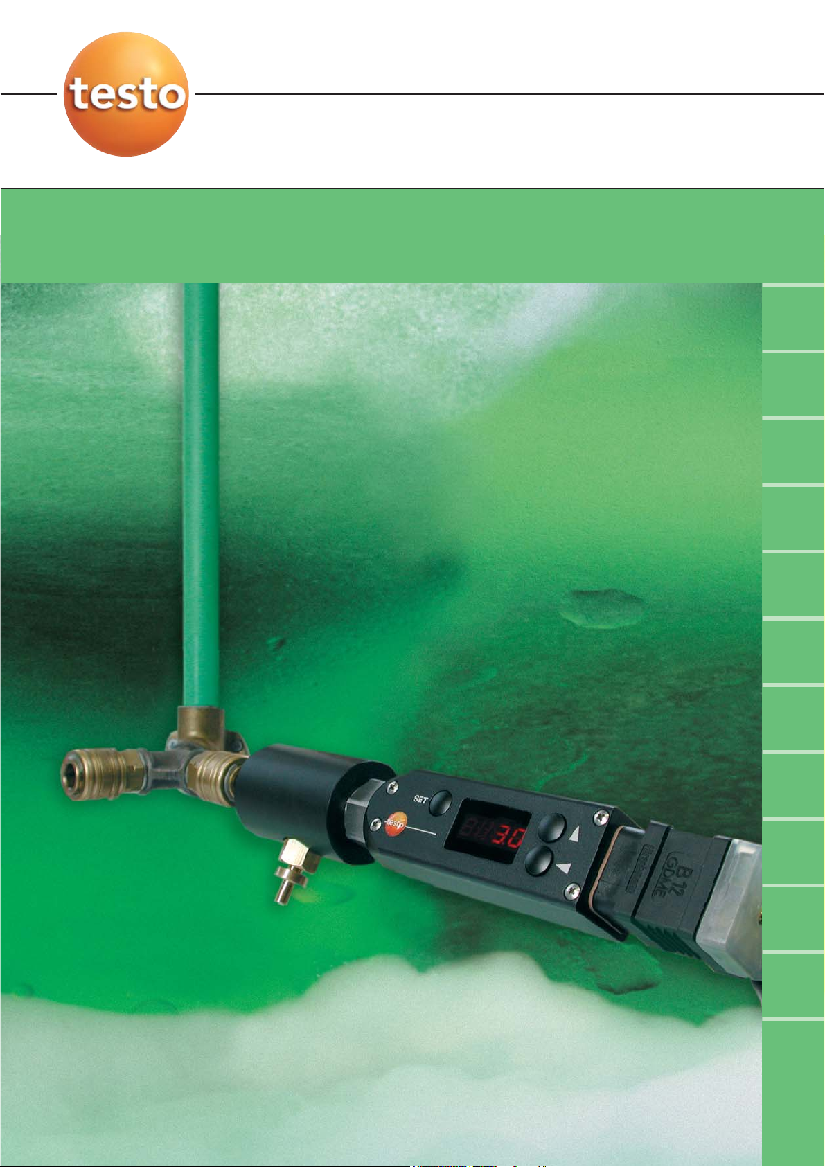
Humidity Monitoring in Compressed Air
Increase safety - Cut costs
°C tpd
°F tpd
°C td
atm
°F td
atm
% RH
ppm
V
mg/m
3
°C / °F
testo 6740
Page 2
2
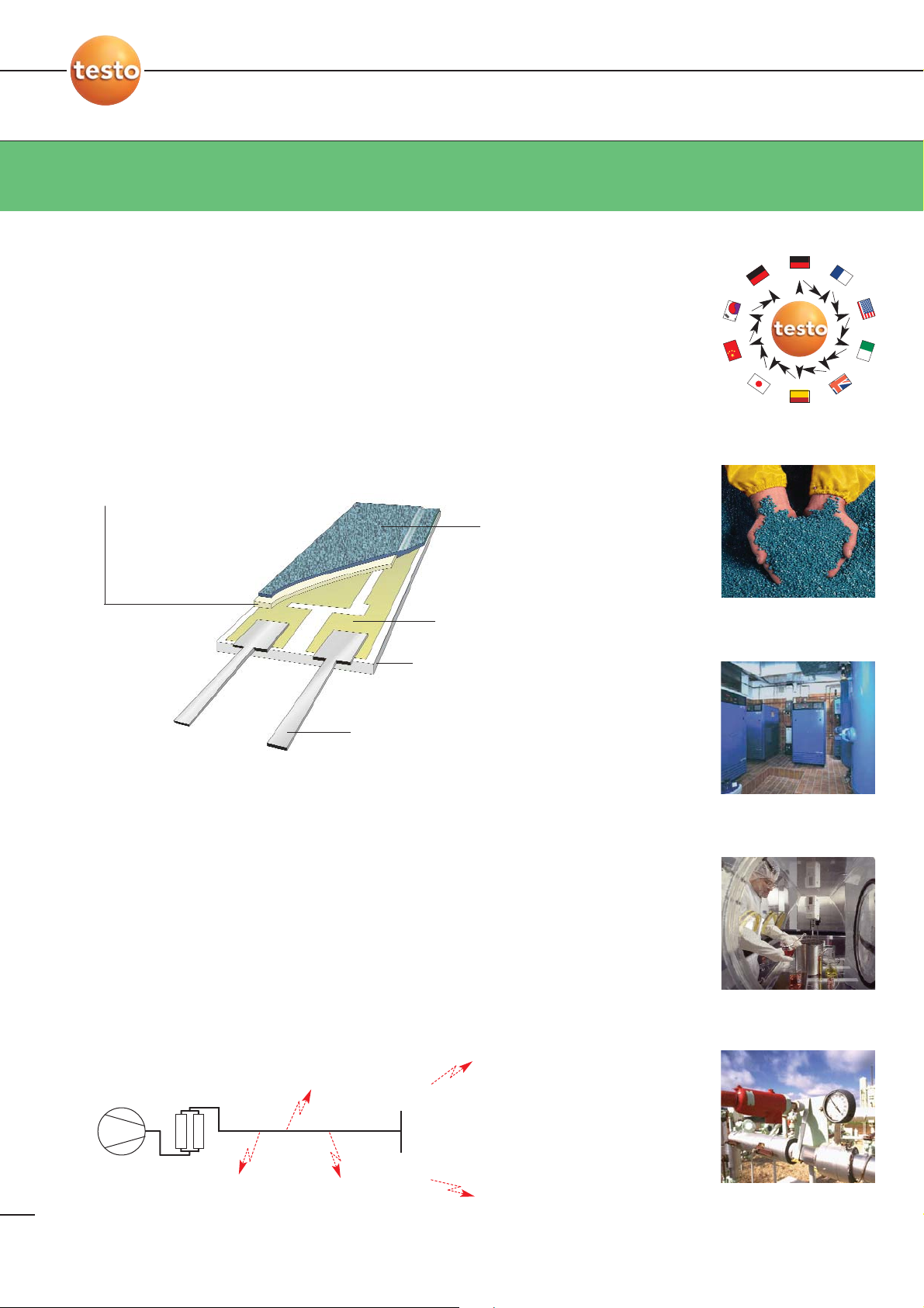
The humidity sensor
2
Optimal for trace humidity measurement
The testo humidity sensor is generally calibrated at several points to ensure minimum deviations. For trace
humidity measurement, a high-precision reference measurement (dewpoint mirror) is used to help carry out a
calibration at -40 °CtP (pressure dewpoint).
To demonstrate the accuracy of testo’s humidity sensors, five sensors were extensively tested in a large number
of international calibration institutes over a 5-year period. All the measurement results confirmed the high
accuracy of 1% RH.
Monitor trace humidity, avoid damage
Dry air, compressed air and dry gases are used in all areas of industry. Humidity is normally
undesirable because it can cause damage or impair the quality of the end product, as the
graphic underneath shows.
04/96
10/96
12/96
07/97
09/98
10/98
03/99
10/00
03/01
08/96
10/96
09/98
10/98
04/00
08/01
PTB
P
T
B
12/00
NRC
CRM
09/00
KRISS
J
Q
A
INTA
N
P
L
IMGC
N
IST
C
E
T
IA
T
·
That’s why you need the testo 6740 for effective trace humidity measurement
>>
Compression Distribution Consumer
Corrosion in pipes and
function elements
Pneumatic drives:
- interrupted lubrication
- mechanical damage
Formation of ice in
cold and external zones
Compressor Drier
e.g. medical
compressed air
Moist powder
conglutinated
Bacterial growth
(European drug
legislation)
e.g. transport air for
pharmaceutical powder
·
Gas engineering: humidity causes damage and reduces the
value of the gas in the system
Granulate drying: dry air is a
requirement for product quality
Medical compressed air:
minimum humidity as a hygiene
requirement
Compressed air systems: drier
monitoring to avoid damage
caused by humidity
05/00
Dielectric layer
Polymer, changes dielectricity as
a function of relative humidity
Top electrode
Allows humidity to penetrate to
the dielectric layer and protects
against dirt
Carrier
Ceramic substrate for
mechanical protection
Connection pins
Special anti-
corrosion design
Bottom electrode
Page 3
33
Safeguard quality - Cut costs
What is compressed air quality?
The international standard ISO 8573 defines seven classes of
compressed air quality and lays down the humidity, the oil
content, the particle content etc. which the compressed air is
allowed to have. Class 1 represents the highest requirements.
Class 4 is satisfied if, for instance, the pressure dewpoint does
not exceed 3 °CtP or 37 °FtP or an absolute humidity of 6 g
water vapour per m3 or 8,150 ppmV(parts per million, relative to
the volume).
The main way of ensuring compliance with a quality class
involves installing a suitable drier. Its monitoring and, where
appropriate, its control (see below), is handled by the
testo 6740.
How can costs be reduced?
Of course, the main reason for using the testo 6740 is to
monitor and avoid excessive humidity in the system so as to
avoid damage (cf. p. 2 below). In addition, dryer operating costs
can be reduced sharply.
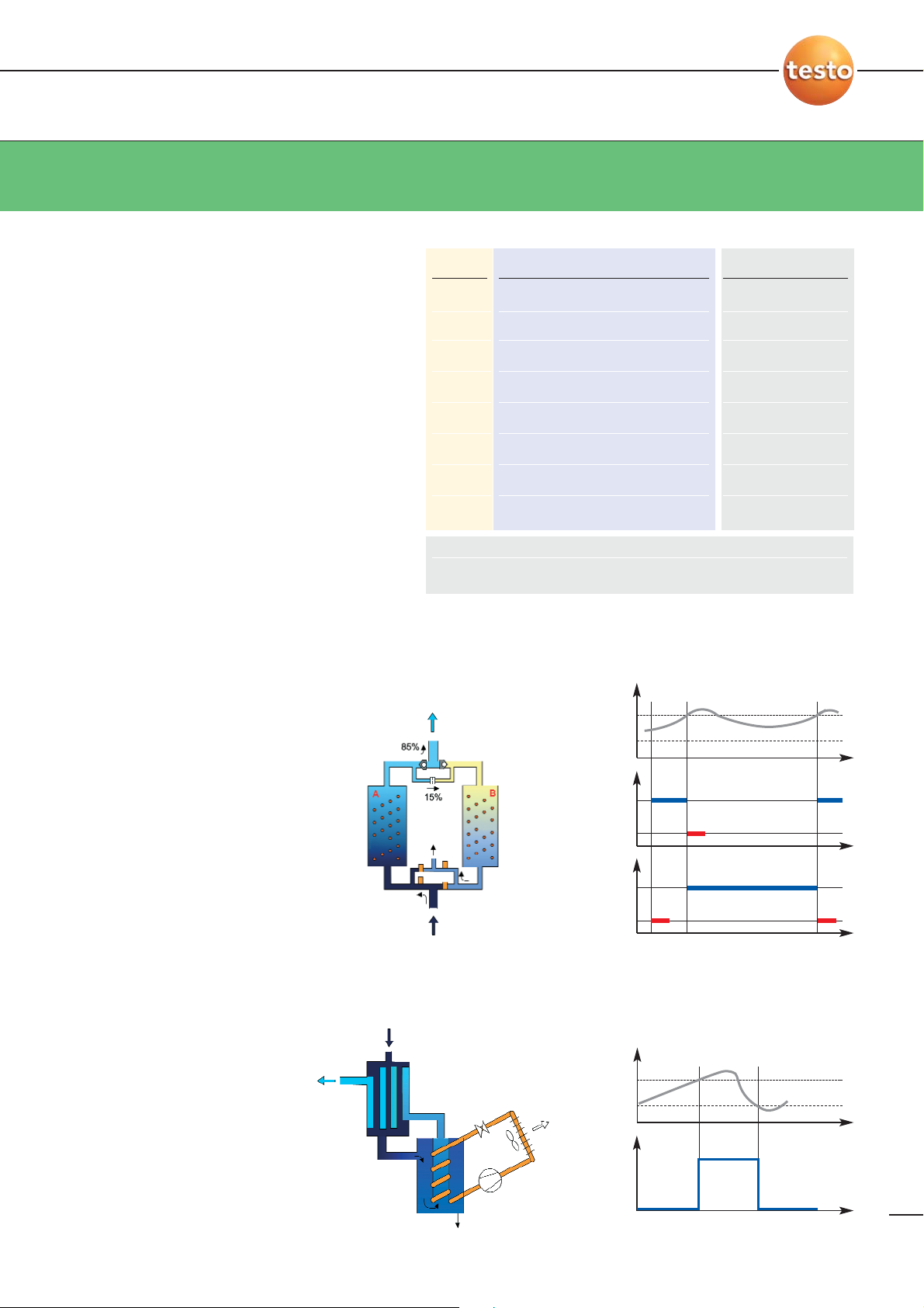
Adsorption driers:
If chamber switchover is humidity-controlled
using the testo 6740 rather than being time-
controlled (see diagram on the right), the dry
phases (blue) are normally much longer than the
regeneration phases (red). During this time no
regeneration air must be generated, so that the
compressors can be reduced from 100% to
about 85% volumetric flow rate. This results in
significant savings in operating costs.
Dry
compressed air
Humid
compressed air
Condensate
Humid
compressed air
Cooling driers:
In non-critical systems, low-temperature driers
can be switched off completely when air humid-
ity is low (e.g in the winter). The testo 6740
supplies the humidity measurement here as
well. If the humidity surges that occur when the
low-temperature driers are switched on are to
be avoided, a downstream low-temperature
drier can be kept in continuous operation to
trap this humidity. This results in tangible
savings in operating costs.
On -22°
Vessel A
Pressure dewpoint
(°Ctpd)
Drying
Regeneration
Drying
Regeneration
Vessel B
On -22°
Off -28°
Vessel A
Drying
Regeneration
Drying
Regeneration
Vessel B
Time
10°
2°
Low-
temperature
driers
Pressure
dewpoint
temperature
TimeOff
On
Off
Equipment Compressed air drier
Monitoring/
Control testo 6740
Typical application
Semi-cond. prod.
Granulate drier
Transport air
Pneu. tube conveyor
Vacuum eng.
Working/energy air
Blow air
ISO 8573
Class
1
2
3
4
5
6
7
Trace humidity
°Ctpd °Ftpd g/m
3
ppm
v
-70 -94 0.003 4
-40 -40 0.12 163
-20 -4 0.88 1200
3 37 6 8150
7 44 7.8 10600
10 50 9.4 12800
-- - -
Page 4

44
Features and benefits
Bright 7-segment display (optional)
- Housing can be rotated by 350°
The right process connection
- G
1
/2 or NPT1/2“
- Pressure-tight up to 50 bar
- With optional measurement chamber
Ultra-easy menu operation (cf. p.6) via buttons
- Select the humidity variable
- Change the scaling
- Set alarms, incl. hysteresis
- Carry out local 1-point calibration
- Test analog signal and alarm outputs
- Call up historic min./max. values
The long-term stable testo humidity sensor
with protocolled precision calibration at
residual humidity -40 °Ctpd
• Maximum reliability
- Long-term stability, testo humidity sensor applied 100,000 times over
- Demonstrably correct indication of measurement ranges and data
- Highest manufacturing quality
• Calculation of the most important trace humidity variables
- e.g. °Ctpd, °Ctd atmospheric, ppm
v
• Calibration protocol
• Convenient operation
- Via the display menu without additional aids
- Without display via the internal interface and
scaling adapter software (cf. p. 6)
- Local 1-point calibration
•
Analog output 4 .. 20 mA (2-wire)
• 2 limit signal outputs (optional)
- Pre- and main alarm
as floating contact
- 2 LEDs displaying the alarm status
Housing
Material Plastic, polyacrylamide
Dimensions 199.5x37 x37 (with analog output plug)
203.5x37 x37 (with limit signal output plug)
Ambient temperature -20 ... 70 °C
Storage temperature -40 ... 80 °C
Protection type IP 65
Rotation of housing By 350° (to align display)
Sensor and sensor protection
Humidity sensor testo humidity sensor with protocolled
trace humidity adjustment at -40° Ctpd
Temperature sensor NTC
Sensor guard Sintered stainless steel cap
Meas. uncertainty
Humidity +/- 1 K at 0 °Ctpd
+/- 3 K at -20 °Ctpd
+/- 4 K at -40 °Ctpd
Temperature +/- 0.5 K (0 ...50 °C)
Limit signal outputs (optional, 0554.3302)
Contacts
2 floating NO contacts, max. 30 V/0.5 A
Operating points
Standard: 4 °/12 °CtP,
with freely programmable display
Measuring range
Pressure dewpoint temperature (trace humidity) - 60 to +30 °Ctpd
at pressure dewpoints < 0 °Ctpd display of
frost point, at > 0 °Ctpd of dewpoint
Temperature 0 ... 50 °C
Atmospheric dewpoint - 80 ... - 15 °Ctd (at 30 bar rel.)
(cf. diagram on p.7) - 70 ... + 10 °Ctd (at 3 bar rel.)
- 60 ... + 30 °Ctd (at 0 bar rel.)
Pressure resistance testo 6740: Up to 50 bar absolute
Measurement chamber 0554.3303: Up to
15 bar absolute
Analog output
Signal 4 ... 20 mA, two-wire
Scaling Freely scalable via display/buttons
Standard: 4 ...20 mA = -60 ... +30 °Ctpd
Output variables °Ctpd, °Ftpd, °CtA (atm. dewpoint),
°FtA, %RH, ppm
V
, mg/m3, °C, °F
Resolution 12 Bit
Accuracy +/- 40 µA
Supply
Voltage 24 VDC (10 ... 30 VDC allowed); with alarm plug (0554 3302) 20 to 28 VDC
Max. load 10 VDC: 100 Ohm, 30 VDC: 950 Ohm, cf. p.7
EMC According to Directive 89 /336 EEC
Technical data testo 6740
Page 5

55
System components, ordering details
X
Basic instrument (incl. plug for analog signal output)
testo 6741, G 1/2 thread, without display 0555 6741
testo 6742, NPT 1/2“ thread, without display 0555 6742
testo 6743, G 1/2 thread, with display 0555 6743
testo 6744, NPT 1/2“ thread, with display 0555 6744
Accessories
Cable connection plug for analog output 4 ... 20 mA, with
2 floating switch contacts and 2 LEDs 0554 3302
Measurement chamber (for 6741, 6742), up to 15 bar 0554 3303
Cooling coil (up to 200 °C, use only with measurement chamber) 0554 3304
Scaling adapter for testo 6741 / 6742 incl. software 0554 3305
ISO calibration certificate, two calibration points (-10 °/-40 °Ctp at 6 bar) 0520 0136
ISO calibration certificate, pressure dewpoint (-40 °...0 °Ctpd at 6 bar)
Basic costs 0520 0116
Per calibration point (please indicate) 0520 0116
External display testo 54-2AC, 2 limit signal outputs (up to 300 VAC, 3 A),
supply 230 VAC
5400 7553
2 m teflon tube with compressed air connections 0669 2824/4
Power supply (bench unit) 90...264 VAC / 24 VDC (350 mA) 0554 1748
Power supply (DIN rail mounting) 90...264 VAC / 24 VDC (3 A) 0554 1749
Ordering data testo 6740 Order no.
Customised combinations
Every measuring point can be optimally configured. With or
without a display, with European G 1/2 thread or American
NPT 1/2” thread. With or without limit signal output.
Directly assembled, with measurement chamber or with
cooling coil. All combinations are possible, ensuring your
needs are met optimally.
Measurement chamber (0554 3303)
for optimal flows past the sensor
(valve can be infinitely adjusted) and
quick installation
Selection advice: choosing the right components for your application
For process temperatures > 50 °C (up
to 200 °C), use a cooling coil (0554.3304)
& measurement chamber (0554.3303).
For dirty, oily media, connect a
40 µm filter upstream
If neither A nor B is required:
just screw directly into the G1/2 or
NPT 1/2” thread. Depressurised
tube required during installation.
Use a measurement chamber
(0554.3303) for rapid assembly (no
depressurising before installation) and
better response time from the sensor (flow
past sensor can be infinitely adjusted)
Cooling coil (0554 3304)
for process temperatures
50 ...200 °C (only with
measurement chamber)
Teflon tube (0669 2824/4)
for dry air
The 4 types of the testo 6740 family
A
A
A B
B
C
For atmospheric dry air (e.g.
granulate driers), a teflon tube is
used and the valve of the
measuring chamber is opened fully.
At process temperatures
> 50 °C, connect a cooling coil
upstream.
EN
EN
testo 6741
G 1/2
G 1/2 thread
NPT 1/2”
NPT 1/2” thread
testo 6743
with display
testo 6744
with display
testo 6742
Standard: Analog output
4 ..20 mA (2-wire)
Optional (0554 3302):
2 limit signal outputs integrated
Analog output 4 ..20 mA (2-wire)
+ 2 limit signal outputs (floating)
+ 2 LEDs
without display with display
G 1/2 0555.6741 0555.6743
NPT 1/2” 0555.6742 0555.6744
C
C
B
In main line:
behind drier
Compressed air
quick connection
(plug NW 7.2)
Compressed air
quick connection
(plug NW 7.2)
G 1/4
internal
thread
G 1/2
internal
thread
Compressed air
quick connection
(jack NW 7.2)
Page 6

6
The ideal operating concept
6
Easy to operate with or without a display
Does the unit have to be changed from °Ctpd to ppmVor do the operating points need to be corrected? These and many other settings can be
easily configured via the display. Or - and this is particularly advantageous for OEM customers such as manufacturers of compressed
air driers - these adjustments can be handled by a PC running the scaling adapter software 0554.3305, even without a display.
With display, testo 6743, testo 6744
Without display, testo 6741, testo 6742
The display menu
Fully oriented to field requirements: Alternating display value and unit, option of switching off the display, password protection,
unit selection, etc. Try it out! You will certainly appreciate the intuitive operation.
The scaling adapter software permits mobile
access, perfect for OEM or service personnel
The display and buttons enable ultra-easy
menu operation with maximum convenience for the user
• Firmware version
• Digital values
• Keyboard test
• Further information
• Set absolute pressure
• Display min./max. value
• Test analog output
• Set/test limit signal output etc.
• Change units
• Change scaling
• Single-point calibration
• Reset
cf. below “The
display menu”
Select unit
Define scale
RSTADJALARMPROG
ResetReference
value input
(1-point
adjustment)
Lower
alarm
Upper
alarm
Hysteresis
Test
switching
outputs
Min. values
Max. values
User code
Time delay
On/Off
On/Off
Analog signal test
Absolute pressure**
UNIT
°Ctpd
°Ftpd
°CtA
°FtA
%RH
ppm
v
mg/m
3
°C
°F
4 mA *
20 mA *
* testo 6740 specifies typical scale defaults for the chosen UNIT.
These can be changed as desired.
** Only necessary for UNITs °CtA, °FtA (atm. dewpoint) or mg / m3(absolute
humidity)
CODE
Measuring mode
No display
Switch off
display
Alternating display
Measure value 6 s Unit 2 s
SET SET
1
1
2
2
3
3
Page 7

77
Pressure dewpoint or atmospheric dewpoint? - Wiring
Pressure dewpoint or atmospheric dewpoint?
Atmospheric air is able to store more water vapour than compressed
air. If the compressed air is cooled down, it reaches its dew
point (“pressure dewpoint” in °CtP or °FtP) at higher temperatures,
while atmospheric air can be cooled down further until condensate
is first produced (“atmospheric dewpoint” in °CtA or °FtA).
Only the pressure dewpoint is relevant to the monitoring of
compressed air systems for trace humidity because this indicates
how far away the “danger threshold” (= dewpoint) is. Since some
users are accustomed to working with an atmospheric dewpoint,
however, the testo 6740 allows the option of outputting both the
pressure dewpoint and the atmospheric dewpoint (the absolute
process pressure is input for the latter).
Pressure dewpoint (35 bar) is relieved to 4 bar. The pressure
dewpoint thus falls from 10 °CtP to -23 °CtP
Compressed air (7 bar) has a pressure dewpoint of 20 °CtP. This
corresponds to an atmospheric dewpoint of -8 °CtA.
The electrical wiring
What is RL?
The total resistance of the 2-wire connection, con-
sisting of the line, and possibly an external display and
control unit
Standard plug (4..20 mA, 2-wire)
Signal +
4...20 mA
Signal -
R
L
U=20..28
VDC
With switch contact plug
Order no. (0554 3302)
(4..20 mA, 2-wire plus 2
floating switch contacts):
8-core cable
Signal +
4...20 mA
Signal -
R
L
U=10..30
VDC
Supply +
Supply -
US ±
LS ±
ON, if value > US+HYS
OFF, if value < US-HYS
ON, if value > LS+HYS
OFF, if value < LS-HYS
RL= Load impedance, external load
U
10 V 300 Ohm -
24 V 650 Ohm 650 Ohm
30 V 950 Ohm -
LS = Lower Switch US = Upper Switch
B
B
A
B
A
11
2
ON
OFF
LS
HYS
ON
OFF
US °Ctpd
HYS
Absolute humidity [g/m3]
Atmospheric dewpoint [°CtA]
Pressure dewpoint [°CtP]
60
50
40
30
20
10
0
-10
-20
-30
-40
-50
-60
-70
-70 -60-50 -40 -30 -20 -10 0 10 20 30 40
0,003
0,011
0,038
0,117
0,330
0,690
2,156
4,868
9,356
17.148
30,078
50,672
70
35
14
7
4
2,5
0
Positive
pressure p
0
[bar]
11
2
Page 8

Subject to change without notice.
0981.2194/hd/AC/11.2003
 Loading...