

Page 1
Instruction manual en
testo 6721 Dew point monitor
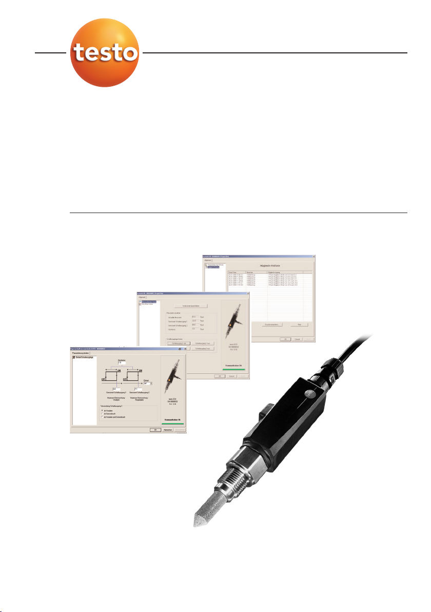
P2A software for testo 6721
Page 2

2
Page 3

3
Contents
Contents 3
Safety and the environment 4
Part 1: testo 6721
Specifications 5
Commissioning 8
Assembling the instrument 8
Wiring the instrument 9
Connecting the instrument 11
Parameterizing/adjusting/analyzing the instrument 11
Maintaining the product 11
Tips and assistance 12
Part 2: testo P2A Software
Specifications 13
First steps 14
Installing the software/driver 14
Starting the software 14
Product description 15
Using the product 16
Tips and assistance 19
????
Contents 3
deenfresitptsvnl
Page 4

4 Safety and the environment
Safety and the environment
About this document
i Please read this documentation through carefully and familiarize yourself with
the product before putting it to use. Keep this documentation to hand so
that you can refer to it when necessary. Hand this documentation on to any
subsequent users of the product.
i Pay particular attention to information emphasized by the following symbols:
· Important.
Avoiding personal injury/damage to equipment
i Never store the product together with solvents and do not use any
desiccants.
i Only operate the product properly, for its intended purpose and within the
parameters specified in the technical data. Do not use force.
i Only carry out the maintenance and repair work that is described in the
documentation. Follow the prescribed steps when doing so. Use only OEM
spare parts from Testo.
Protecting the environment
i Send the product back to Testo at the end of its useful life. We will ensure
that it is disposed of in an environmentally friendly manner.
Page 5

5
deenfresitptsvnl????
testo 6721 - Specifications
PART 1: TESTO 6721
Specifications
Functions and use
The 6721 is a dew point monitor for monitoring trace humidity in the following
applications:
· Trace humidity monitoring in compressed air systems, e.g. upstream of pneumatic
machines.
· Monitoring (compressed air) low-temperature driers.
· Monitoring (compressed air) membrane driers.
The product must only be assembled, wired and connected by qualified
personnel.
The product must
not
be used in areas at risk of explosion!
Ordering overview
0555 6721 Axx / Fxx / Kxx
A01 G½" process connection
A02 NPT ½" process connection
F01 Dew point °Ctd / GW 1 / GW 2 / hysteresis
F02 Dew point °Ftd / GW 1 / GW 2 / hysteresis
K01 German/English instruction manual
K02 French/English instruction manual
K03 Spanish/English instruction manual
K04 Italian/English instruction manual
K05 Dutch/English instruction manual
K06 Japanese/English instruction manual
K07 Chinese/English instruction manual
Page 6
6 testo 6721 - Specifications
33
176
72
56
➋
92
42
➊
➌
Technical details
Parameters, measuring range
· Dew point temperature (trace humidity):
-30 - 30 °Ctd/-22 - 86 °Ftd
Accuracy
· Dew point temperature at 25 °C/77 °F process
temperature:
±4 K (-30…-20°Ctd/-22…-4°Ftd),
±3 K (-20…-10°Ctd/-4…14°Ftd),
±2 K (-10…0°Ctd/14…32°Ftd),
±1 K (>0°Ctd/>32°Ftd)
Resolution
· 0.1 °Ctd/0.1 °Ftd
Meas. cycle
· 1/s
Other instrument data
· Humidity sensor: Testo humidity sensor (with special
trace humidity adjustment)
· Temperature sensor: NTC
· Output variable: Dew point (°Ctd or °Ftd) via two
switching outputs
· Measuring medium: Compressed air (filtered and
dried, ISO 8573 classes 2-4-2)
· Operating temperature: 0 - 50 °C/32 -122 °F, ideally
between 10 °C and 35 °C/50 °F
· Pressure range: max. 20 bar (abs)
· Connection: G½" (0555 6721-A01) or NPT½"
(0555 6721-A02)
· Supply: 24 V AC/V DC (20 - 30 V AC/V DC permissible)
· Power consumption: 50 mA
· Interfaces: mini-DIN interface for
parameterizing/adjusting/analyzing using testo
P2A Software
· Switching outputs: 2 x floating, switching voltage
24 V DC/V AC, switching current 0.5 A, optional wiring
as NC or NO contact
· Limit values (2x) and switching hysteresis (1x):
Free choice within the measuring range by means of
order code, or setting via testo P2A Software
· Sensor protection: Sintered stainless steel filter,
12 mm diameter
· Housing material: plastic PAA GF30
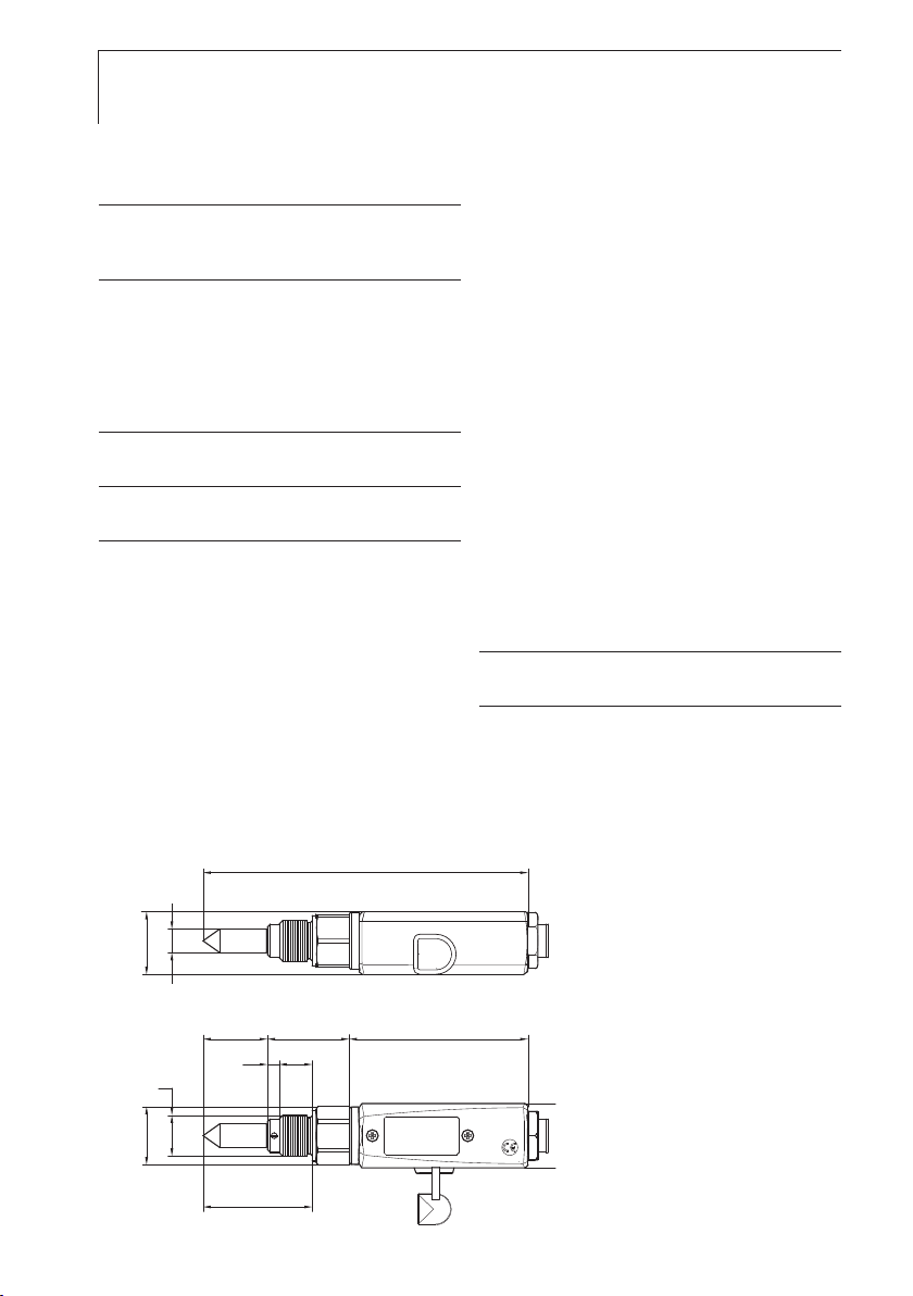
· Housing dimensions: 167 x 33 x 33 mm
· Protection class: IP65 (with adapter connected or with
protective tab on closed interface.)
· Ambient temperature: 0 - 50 °C/32 - 122 °F
· Storage temperature: -40 - 70 °C/-40 - 158 °F
· Weight: 240 g
Directives, standards and tests
· EC Directive: 2004/108/EEC
Warranty
· Duration: 2 years
· Warranty conditions: see website
www.testo.com/warranty
Dimensions:
21ø
33
167
0555 6721-A01: G½
0555 6721-A02: NPT½"
Installation depth in process
Wrench size
Page 7

7
deenfresitptsvnl????
testo 6721 - Product description
Product description
At a glance
Sensor protection: Sintered stainless steel cap.
Fixing the sensor assembly: Threaded pin.
Screwed socket: G ½ (0555 6721-A01) or NPT ½" (0555 6721-A02).
Fixing the housing cover: 2 countersunk screws.
Connector socket for switching contact connector.
Connector socket for external interface (mini-DIN Testo), plug.
Factory settings
Characteristic 0555 6721-F01 0555 6721-F02
Unit °Ctd °Ftd
Limit value for switching output 1 5 45
Limit value for switching output 2 10 55
Hysteresis 1 2
Page 8

8 testo 6721 - Commissioning
Commissioning
Assembling the instrument
²
Assembling tthe iinstrument aat tthe pprocess cconnection:
If assembling without a measurement chamber: The sections of pipe
where the instrument is assembled are depressurized.
1 To ensure leaktightness: Wrap the thread of the screwed socket using
sealing tape (e. g. PTFE) or insert a copper sealing ring (internal diameter
of 21 mm).
2 Assemble the instrument according to the application in hand:
Applications/assembly options
A Process temperatures < 15 °C or > 35 °C (max. 200 °C):
Assembly with measurement chamber and cooling coil.
B Process temperatures of 15 - 35 °C, quick assembly/dismantling of instrument is required, sufficient
incident flow through sensor (1l/min) not present:
Assembly with measurement chamber.
If media are contaminated: connect preliminary filter (0554 3311) upstream
C Process temperatures of 15 - 35 °C, installation of sensor directly in the process is possible, quick
assembly/dismantling of instrument is not required, sufficient incident flow through sensor (1l/min)
present, compressed air is not contaminated:
Assembly without measurement chamber and without cooling coil
A
A
➊➋
➌
G 1/2
➎➍
0555 6721-A01
➏
B
G 1/2
C
NPT 1/2"
C
NPT 1/2"
0555 6721-A02
Page 9

9
deenfresitptsvnl????
testo 6721 - Commissioning
Process connection, quick-release compressed-air fastener NW 7.2 or G 1/2" or
NPT 1/2" thread
PTFE tube (0669 2824/4) or cooling coil (0554 3304).
Preliminary filter 0554 3331
When using the preliminary filter, it must be ensured that there is
sufficient flow (1 l/min) in the measurement chamber by cleaning the
filter regularly.
Measurement chamber (0554 3303).
testo 6721 dew point monitor.
Assembling the measurement chamber on the dew point monitor.
Only apply force at the hexagon (AF 27)!
Wiring the instrument
The testo 6721 is supplied with the right connector to which a cable can be
soldered by the customer. Alternatively, the 5 m accessories cable with the
pre-fabricated connector (0554 6720) can be used.
²
Fabrication oof cconnection ccable bby tthe ccustomer:
Testo recommends an 8-wire line with a tightly plaited shield, wire crosssection of 0.25 - 0.5 mm².
1 Remove top part of connector from bottom
part of connector (screw cap).
2 Open line fixture on top part of connector
(screw cap/union nut ) and feed through
lines of connecting cable.
Page 10
10 testo 6721 - Commissioning
3
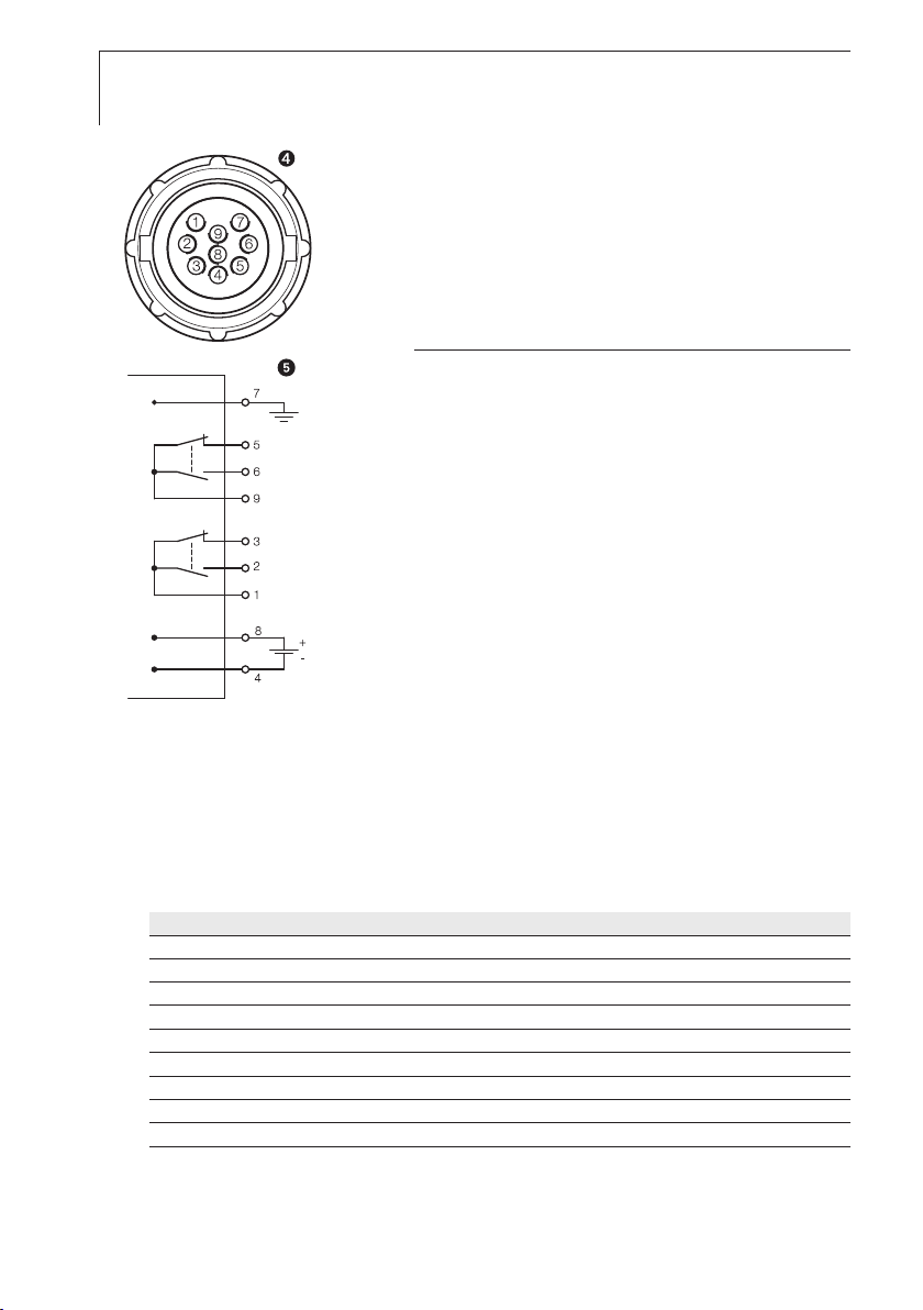
Solder ends of lines to the pins in the bottom
part of the connector :
Two separate switching points can be created
using the two switching contacts which can
each be configured as either a NC contact
(1-3, 9-5) or NO contact (1-2, 9-6)
.
Assignment of the pins
1 Root/pin for switching contact 1
2 NO contact for switching contact 1
3 NC contact for switching contact 1
4 Supply -
5 NC contact for switching contact 2
6 NO contact for switching contact 2
7 Functional earth
8 Supply +
9 Root/pin for switching contact 2
4 Fasten top part of connector to bottom part
of connector (screw cap) and close line fixture
(screw cap/union nut).
²
Feeding wwiring tthrough wwith aaccessories ccable 00554 6720:
i Shorten length of line (5 m) if necessary.
i Connect the ends of the line according to the colour assignment:
Two separate switching points can be created using the two switching
contacts which can each be configured as either a NC contact (grey-pink,
brown-green) or NO contact (grey-yellow, brown-white).
Colour Assignment
grey root/pin for switching contact 1
yellow NO contact for switching contact 1
pink NC contact for switching contact 1
red supply +
green NC contact for switching contact 2
white NO contact for switching contact 2
black Functional earth
blue supply brown root/pin for switching contact 2
Page 11

11
deenfresitptsvnl????
testo 6721 - Commissioning
Connecting the instrument
²
Connecting tthe sswitching ccontact cconnector tto tthe iinstrument:
i Fasten switching contact connector to the port of the instrument
(connector with rotary protection).
Parameterizing/adjusting/analyzing the
instrument
The instrument is parameterized, adjusted and analyzed using the P2A
Software, see “Part 2: testo P2A Software”.
Maintaining the product
±
Cleaning tthe hhousing:
i Clean the housing with a damp cloth (soap suds) if it is dirty. Do not use
aggressive cleaning agents or solvents!
±
Cleaning tthe ssensor pprotection ccap, mmeasurement cchamber, ccooling ccoil aand
preliminary ffilter:
If used in process conditions involving oil or dust, the sintered stainless steel
filter and, if used, the measurement chamber, preliminary filter and cooling
coil must be cleaned regularly.
i Remove the measurement chamber and cooling coil/unscrew sensor
protection cap/unscrew preliminary filter and blow out with compressed
air or place in an ultrasonic bath.
±
Cleaning tthe ssensor:
During cleaning, avoid touching the sensor at all costs.
Do not clean the sensor mechanically, as this can damage the cover
electrode.
i Screw off filter cover.
i Carefully rinse the mirrored surface with isopropyl alcohol and/or distilled
water.
i Allow the sensor to dry completely.
Page 12

12 testo 6721 - Tips and assistance
Tips and assistance
Questions and answers
Question Possible causes/solutions
Faulty switch signal - Test limit values and hysteresis using P2A Software
- View adjustment history using P2A Software: Faulty adjustment?
If we could not answer your question, please contact your dealer or Testo
Customer Service. Contact details can be found on the guarantee card or on
the Internet at: www.testo.com
Accessories and spare parts
Designation Article no.
Parameterizing, adjusting and analyzing software (P2A Software incl. adapter cable for USB to mini-DIN) 0554 6020
Measurement chamber for optimum incident flow through humidity sensor, max. 15 bar, for G½" thread 0554 3303
Cooling coil for process temperatures above 35 °C (up to 200 °C) 0554 3304
Preliminary filter to protect measurement chamber and sensors against contamination 0554 3311
Sintered stainless steel filter 0554 0647
Connector with 5 m cable 0554 6720
Alarm box for testo 6721 dew point monitor, without cable 0555 6720 0554 6722
PTFE tube with compressed air connections, 2 m, max. 9 bar 0699 2824/4
Mains unit (bench unit), 90 - 264 V AC/24 V DC (350mA) 0554 1748
Mains unit (top-hat rail mounting), 90 - 264 V AC/24 V DC (2.5A) 0554 1749
For a complete list of all accessories and spare parts, please refer to the
product catalogues and brochures or look up our website at: www.testo.com
Page 13

13
deenfresitptsvnl????
testo P2A Software - Specifications
PART 2: TESTO P2A SOFTWARE
Specifications
Functions and use
The testo P2A Software (0554 6020) is parameterizing, adjusting and analyzing
software for Testo transmitters. It is not supplied with the testo 6721.
System requirements
Operating system
· Windows 2000 SP4
· Windows XP
Computer
· Pentium processor of at least 400 MHz or equivalent
· 128 MB RAM
· Graphics resolution of at least 1,024 x 768
· Unused hard drive capacity of at least 15 MB
· CD-ROM drive
· USB interface or corresponding adapter
Page 14

14 testo P2A Software - First steps
First steps
Installing the software/driver
The CD supplied with the testo 6721 contains an update of the P2A Software
including all the latest instrument drivers. Install this update once you have
installed the P2A Software (0554 6020).
Administrator rights under Windows® 2000 and XP are required for the
installation of the testo P2A Software program.
±
Installing tthe PP2A SSoftware:
1 Insert the “P2A Software” CD (0554 6020).
If the installation program does not start automatically:
i Start Setup.exe file from the CD-directory (access via My Computer or
Windows Explorer).
2 Follow the instructions of the installation program.
±
Installing tthe UUSB ddrivers:
The USB driver CD is supplied with the P2A Software
Before installing the USB drivers, please read the separate documentation
enclosed with the USB driver CD.
The installation of the USB driver is the prerequisite for the faultless use of
the P2A software.
±
P2A SSoftware uupdate:
1 Insert the product CD (supplied with the testo 6721).
If the installation program does not start automatically:
i Start Setup.exe file from the CD-directory (access via My Computer or
Windows Explorer).
2 Follow the instructions of the installation program.
Starting the software
±
Starting tthe pprogram:
i Select: > Programs > Testo > P2A Software.
Page 15
15
deenfresitptsvnl????
testo P2A Software - Product description
Product description
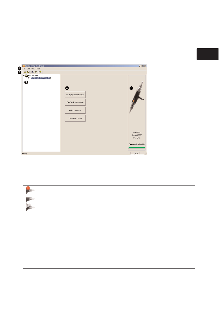
User interface
Menu bar.
Toolbar.
File list: List of all instrument/parameter files.
File symbols
· : Instrument file, connection to the unit has not been established.
· : Instrument file, connection to the unit has been established.
· : Parameter file.
File identifications
· Instrument files: “[Type] [serial number].cfm”; file identifications cannot be changed.
Instrument files contain all the data relating to a particular instrument. These are the parameter data and
represent the parameterization and adjustment history of the instrument.
· Parameter files: “[Type] [serial number] [date] [time].cfp”; file identifications can be changed.
Parameter files only contain parameter data. These can be copied to another instrument or parameter file for
the same type of instrument so that several instruments have the same parameter settings.
List of functions.
File information:
Information displayed
· Instrument files: Type, serial number, firmware version and connection status of the instrument.
· Parameter file: Type, serial number and firmware version of instrument with which the parameter file was
created.
· Connection status (instrument files only): “red” connection is active, “green” connection is inactive.
Page 16

16 testo P2A Software - Using the product
Using the product
±
Establishing aa cconnection wwith tthe ddevice:
Several instruments can be connected to the PC and administered via the
P2A software, but only one connection can ever be active at any one time.
Non-wired instruments can also be connected to the P2A Software for
parameterization/adjustment. The supply to the instruments is then effected
via the USB interface.
1 Connect the USB/mini-DIN adapter to the external interface (mini-DIN) of
the instrument.
2 Connect the USB connector of the adapter to the PC.
- The instrument file for the instrument connected appears in the
instrument file/parameter file list.
±
Selecting tthe iinstrument/parameter ffile, aactivating aa cconnection wwith tthe
device:
i Click on the requisite instrument/parameter file.
- The selected file is highlighted in colour.
- For instrument files only: if a connection with the instrument has been
established, this is automatically activated.
±
Changing aan iinstrument/parameter ffile:
The required instrument/parameter file is selected.
1 Click on Change parameterization button.
2 Enter parameters in the corresponding fields.
3 Click on Apply to confirm entries.
4 To leave the parameterization screen, click on OK.
±
Saving tthe pparameters iin aa pparameter ffile:
The parameter data for the selected instrument/parameter file can be saved.
Only parameter data stored in the standard file can be loaded into an
instrument!
The required instrument/parameter file is selected.
1 In the menu bar, click on File > Save as.
2 Select the storage location and enter the file name.
3 Click on Save to confirm entries.
Page 17

17
deenfresitptsvnl????
testo P2A Software - Using the product
±
Opening aa pparameter ffile:
All parameter files stored in the standard directory path are automatically
displayed in the file list when the software is started. Parameter files stored in
other directories can also be opened.
Only parameter data stored in the standard file can be loaded into an
instrument!
1 In the menu bar, click on File > Open.
2 Select the storage location and click on the requisite parameter file.
3 Click on Open to confirm entries.
±
Copying tthe pparameter ddata:
The parameter data for an instrument/parameter file can be transferred to
another instrument/parameter file for the same type of instrument. History
data for instrument files are not transferred.
1 Select file from which the parameter data are to be copied.
2 In the menu bar, click on Edit > Copy.
3 Select the file which is to be modified.
4 In the menu bar, click on Edit > Paste.
±
Analyzing/testing tthe iinstrument:
The required instrument file is selected.
1 Click on Test/ analyze transmitter button.
2 Perform tasks:
Options
· Carry out factory reset: Reset the parameter unit, scaling limits and adjustment to the factory settings
(values device-specific, see type label).
· Transmitter tests: Manually switch switching outputs to test functionality.
· Min./max. values: Change to display of minimum/maximum values.
3 Click on Apply to confirm entries.
4 To leave the analyzing/test screen, click on OK.
Carrying oout aa 11-ppoint aadjustment:
±
A 1-point adjustment (offset) can be performed. A dew point mirror is
recommended as a reference measuring instrument for pressure dew point
temperatures < 0 °Ctd.
1 Click on Adjust transmitter button.
2 Expose the reference measuring instrument and the instrument to be
adjusted to the same constant conditions and wait for equalization period
to lapse.
Page 18

18 testo P2A Software - Using the product
3
Enter reference value and perform adjustment by clicking on Carry out 1point adjustment.
i To reset an offset value, click on Set Offset to zero.
4 Click on Apply to confirm entries.
±
Viewing aa ttransmitter hhistory:
The current history data as stored in the instrument file are always displayed.
A distinction is made between parameterization and adjustment histories.
Dates and times refer to the PC time when the P2A Software was being
used.
History data are only stored in the instrument file (PC), not in the testo
6721.
1 Click on Transmitter history button.
2 To move between the views, click on Parameterization history or Adjustment
history.
i To print the history data, click on Print.
±
Deleting pparameters ffrom aan iinstrument/parameter ffile:
The parameter data for the selected instrument/parameter file can be
deleted.
The required instrument/parameter file is selected.
1 Right-click on the instrument/parameter file.
2 Select Delete.
3 Click on Ye s to confirm.
±
Creating aa nnew ffolder:
The folder to which the new folder is to be added is selected.
1 In the menu bar, click on File > Add Folder.
2 Give the new folder a name.
Page 19

19
deenfresitptsvnl????
testo P2A Software - Tips and assistance
Tips and assistance
Questions and answers
Question Possible causes/solutions
Connection to instrument cannot
be established. · Check connecting cable and plug contacts.
· USB driver not/incorrectly installed: Re-install.
Adjustment is to be reversed. · Carry out factory reset: Click on
Test/analyze transmitter > click
on Carry out factory reset.
If we could not answer your question, please contact your dealer or Testo
Customer Service. Contact details can be found on the guarantee card or on
the Internet at: www.testo.com
Page 20

testo AG
Postfach 11 40, 79849 Lenzkirch
Testo-Straße 1, 79853 Lenzkirch
Telephone: +49 (0) 7653 681-0
Fax: +49 (0) 7653 681-100
E-mail: info@testo.de
Internet: http://www.testo.com
www.testo.com
0970 6720 de 03 V01.00
 Loading...