

Page 1
testo 6681 · Humidity transmitters
testo 6610 · Probes
P2A software · Parameterizing, adjusting and analyzing
software
Instruction manual en
Page 2

2
Safety and the environment
Safety and the environment
Avoiding electrical hazards
► Never use the instrument and connected probes to measure on or near
live parts!
► Damaged mains cables must only be replaced by authorized personnel.
► Only have the transmitter wired and connected by authorized personnel
with the voltage disconnected.
► You must always comply with the regulations applicable in your country
to the opening and repair of electrical equipment.
Avoiding personal injury/damage to equipment
► Installation, setting and calibration work must only be carried out by
qualified and authorized personnel!
► Only open the instrument when this is expressly described in the
instruction manual for installation, maintenance or repair purp oses.
► Observe the permissible storage, transport and operating temperatures.
► Never store or operate the product with solvents and do not use any
desiccants.
► Do not use the instrument for control purposes at the same time as
operating or servicing the transmitter.
► Only operate the product properly, for its intended purpose and within the
parameters specified in the technical data. Do not use force.
► Carry out only the maintenance and repair work that is described in the
documentation. Follow the prescribed steps when doing so. Use only
OEM spare parts from Testo.
Any additional work must only be carried out by authorized personnel.
Otherwise Testo will not accept any responsibility for the proper functioning of
the instrument after repair and for the validity of certifications.
Protecting the environment
► Send the product back to Testo at the end of its useful life. We will
ensure that it is disposed of in an environmentally friendly manner.
Page 3
About this document
About this document
► Please read this documentation through carefully and familiarize yourself
with the product before putting it to use. Keep this document to hand so
that you can refer to it when necessary. Hand this documentation on to
any subsequent users of the product.
► The following conventions are followed in this document:
Character/
display:
Explanation/example
With the signal word Warning!:
Warns against hazards which could result in serious physical
injury if the precautionary measures indicated are not taken,
e.g.:
De-energize the mains connection before connecting the
transmitter!
With the signal word Caution!:
3
Warns against hazards which could result in minor physical
injury or damage to equipment if the precautionary
measures indicated are not taken, e.g.:
Observe the permissible operating temperature!
Important information, e.g.:
Administrator rights are required to install the program under
Windows
®
2000, XP and Vista.
Aim of action, e.g.:
Assembling the instrument at the process
connection:
Requirement that must be met, e.g.:
USB drivers are installed.
Page 4

4
About this document
1
Steps are numbered if a certain sequence of actions must
be followed, e.g.:
1 Loosen and remove housing screws.
2 Remove the upper part of housing.
" to "
Bold type
…>…
[ ]
CAPITAL
LETTERS
A step is not numbered if there are no further steps or if the
step is optional, e.g.:
▪ Insert probe connector into socket of testo 6681 until
it engages.
Example entries are in inverted commas, e.g.:
The value "0" results in ....
Elements of the program interface or instrument display,
e.g.:
The instrument designation appears in the
instrument/parameter file list.
Select Main Menu Channel 1 and confirm with SET.
Functions/paths within a menu, e.g.:
Start > All Programmes > Testo > Transmitter Software.
Buttons which start an action, e.g.:
Confirm the software key with [OK].
Keys on the instrument or keypad, e.g.:
Press ESC.
Page 5

Contents
Contents
1 TRANSMITTER............................................................................................8
1.1 Specifications...........................................................................................8
1.1.1 Functions and use.......................................................................8
1.1.2 Scope of delivery.........................................................................8
1.1.3 Accessories.................................................................................9
1.1.4 Technical Data............................................................................9
1.1.5 Dimensions ...............................................................................10
1.2 Product description................................................................................11
1.2.1 At a glance................................................................................11
1.2.2 Usable probes...........................................................................12
1.2.3 Display and keypad...................................................................12
1.2.4 Service interface .......................................................................12
1.2.5 Relay board (option)..................................................................13
1.2.6 analog outputs...........................................................................13
1.2.7 Parameters................................................................................13
1.2.8 Scaling ......................................................................................14
1.2.9 Alarm handling..........................................................................17
1.3 Commissioning......................................................................................18
1.3.1 Assembling the instrument........................................................18
1.3.2 Connecting the instrument........................................................21
1.3.3 Adjusting the instrument............................................................33
1.4 Operation...............................................................................................42
1.4.1 Relationship between user menu and mini-DIN socket
is active.....................................................................................42
1.4.2 Key cover ..................................................................................42
1.4.3 Password protection..................................................................44
1.4.4 Structure of user menu..............................................................44
1.4.5 Ov e r v i e w o f t h e t e s t o 6 6 8 1 u s e r m e n u............................................46
1.4.6 The individual main menus .......................................................48
1.5 Status, warning and error messages.....................................................60
1.5.1 Status messages.......................................................................60
1.5.2 Warning messages ...................................................................61
1.5.3 Error messages.........................................................................63
1.5.4 Handling alarm messages ........................................................64
1.5.5 Namur fault conditions ..............................................................66
1.6 Maintenance and cleaning.....................................................................67
1.6.1 Maintaining the instrument........................................................67
1.6.2 Cleaning the instrument............................................................67
5
Page 6

6
Contents
2 TESTO 6610 PROBES...............................................................................68
2.1 Specifications.........................................................................................68
2.1.1 Functions and use.....................................................................68
2.1.2 Design of the probe...................................................................70
2.1.3 Accessories...............................................................................71
2.2 Product description................................................................................71
2.2.1 Overview of probe and filter types ............................................71
2.2.2 testo 6611 wall probe................................................................76
2.2.3 testo 6612 duct probe...............................................................79
2.2.4 testo 6613 cable probe .............................................................83
2.2.5 testo 6615 trace humidity cable probe (self-adjustment)..........90
testo 6617 cable probe (self-monitoring)...............................................94
2.2.6 testo 6622 duct probe...............................................................98
2.2.7 testo 6623 cable probe ...........................................................101
2.3 Commissioning....................................................................................104
2.3.1 Installing the probe..................................................................104
2.3.2 Connecting/removingthe probe to/from the transmitter ..........108
2.4 Maintenance and cleaning...................................................................109
2.4.1 Replacing filters/protection caps.............................................109
2.4.2 Cleaning the instrument and filter/protection cap ...................112
2.4.3 Replacing the sensor ..............................................................112
3 PARAMETERIZING, AD JUSTING AND ANALYZI NG SOFT WARE
SOFTWARE)..................................................................................113
(P2A
3.1 Specifications.......................................................................................113
3.1.1 Functions and use...................................................................113
3.1.2 System requirements..............................................................114
3.1.3 Scope of delivery ....................................................................114
3.2 First steps............................................................................................115
3.2.1 Installing the software/driver...................................................115
3.2.2 Starting the software...............................................................116
3.3 Using the software...............................................................................117
3.3.1 User interface..........................................................................117
3.3.2 Editing instrument/parameter file............................................119
3.3.3 Analyzing/testing the transmitter.............................................128
3.3.4 Adjusting the transmitter.........................................................134
3.3.5 Transmitter history ..................................................................139
Page 7

Contents
4 TIPS AND ASSISTANCE............................................................................145
4.1 Questions and answers.......................................................................145
4.2 Accessories and spare parts...............................................................146
4.2.1 Ordering options for testo 6681 transmitter (0555 6681)..................148
4.2.2 Ordering options for testo 6610 probes (0555 6610)......................152
7
Page 8

8
testo 6681 - 1.1 Specifications
1 Transmitter
1.1 Specifications
1.1.1 Functions and use
The testo 6681 humidity transmitter is used in conjunction with plug-in,
adjusted probes from the testo 6610 range.
Please refer to Chapter 2 testo 6610 probes for information
about commissioning, operating and maintaining the
The testo 6681 humidity transmitter is suitable for the following applications,
for example:
• Process instrumentation
• Clean rooms
• Test benches
• Drying processes
• Production and storage air quality
• Complex room climate applications.
testo 6610 probe.
1.1.2 Scope of delivery
The scope of delivery of the testo 6681 humidity transmitter includes the
following:
• Key cover
• Rear panel bracket
• CD-ROM with catalogue files (PDF) and P2A update (this can onl y be
used in conjunction with the P2A software, which has to be ordered
separately).
Page 9
testo 6681 - 1.1 Specifications
1.1.3 Accessories
The following accessories are available for the testo 6681 humidity
transmitter:
• Protection caps for probes
• Mains unit
• P2A software (parameterizing, adjusting and analyzing software)
• Assembly accessories.
Information about accessories and their order numbers can
be found in Chapter 4.2 Accessories and spare parts or on
the website at www.testo.com.
1.1.4 Technical Data
9
Parameters
- Humidity (various variables and
units)
- Temperature (°C/°F)
Measuring range
- Depends on probe
Accuracy
- Depends on probe
Resolution
- 0.1 % RH or 0.1 °C/0.1 °F
Meas. cycle
- 1/s
Interface
- Mini-DIN for P2A software
(parameterizing and adjusting
software) and handheld testo
400/650
- optional: Profibus-DP module
Voltage supply
- 2-wire: 12 to 30 V DC
- 4-wire (separate signal and supply
lines):
20 - 30 V AC/DC,
300 mA power consumption
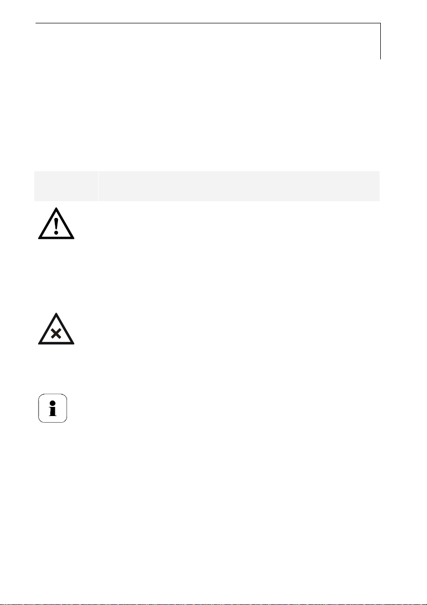
Maximum load
- 2-wire: 100 to 750 Ω
- 4-wire: 500 Ω (power output)
Page 10
10
testo 6681 - 1.1 Specifications
Analog output
- 4 to 20 mA ± 0.03 mA (2-wire) or
- 0 to 1 V ± 1.5 mV (4-wire) or
- 0 to 5 V ± 7.5 mV (4-wire) or
- 0 to 10 V ± 15 mV (4-wire) or
- 0 to 20 mA ± 0.03 mA (4-wire) or
- 4 to 20 mA ± 0.03 mA (4-wire)
Resolution of analog output
- 12 bit
Relay
- 4 relays, 250 V AC/DC, 3 A
(optional)
Display
- 2-line LCD with plain text line
(optional)
Housing operating temperature
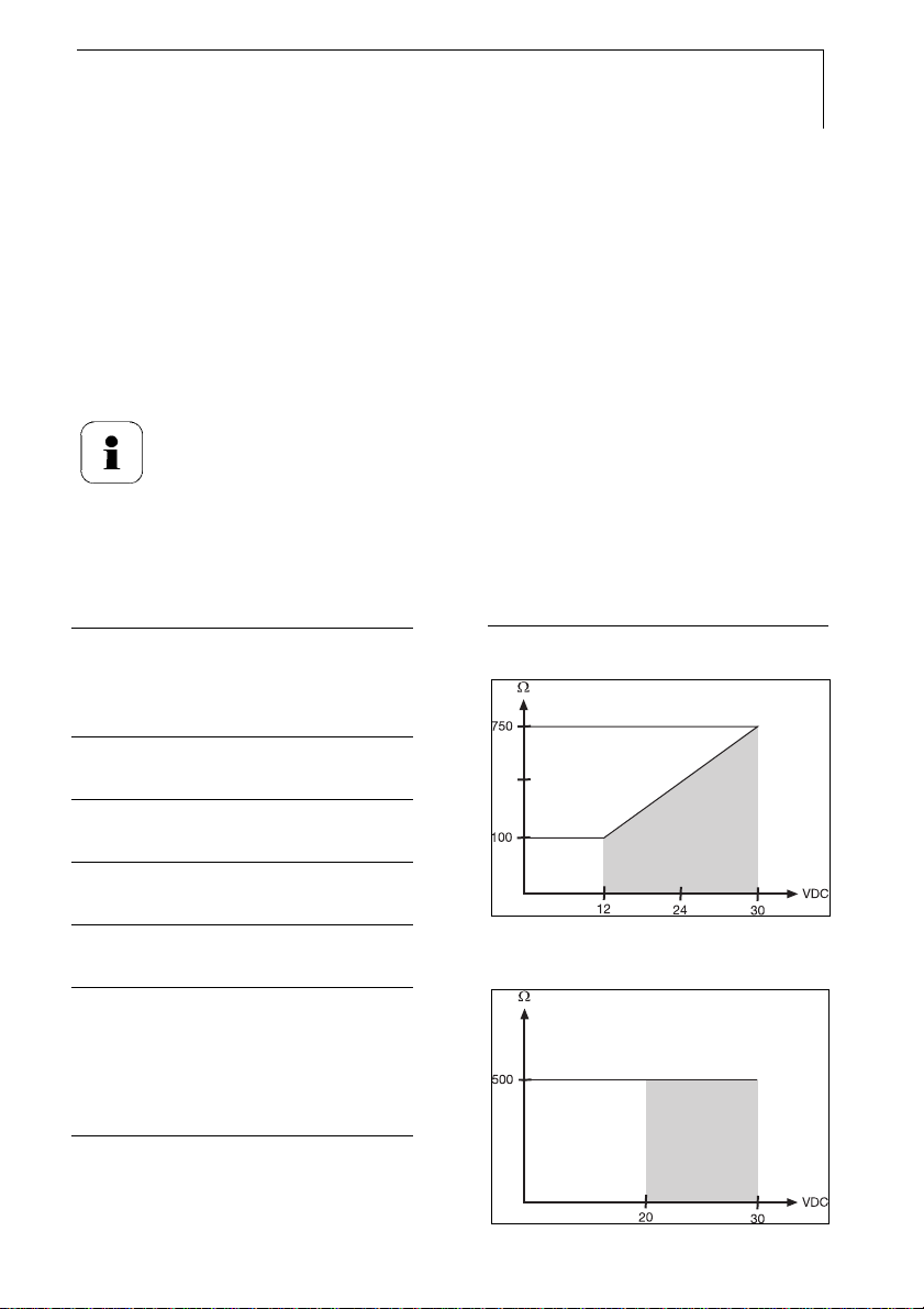
1.1.5 Dimensions
- -40 to 70 °C/-40 to +158 °F, with
display from 0 - 50 °C/+32 to
+122 °F
- With integrated relay: -40 to +60°C
Storage temperature
- - 40 to 80 °C/-40 to +176 °F
Housing, weight
- Metal, 1.960 kg/432 lb
Protection class
- IP 65 only if the transmitter is wired
and/or seal plugs are inserted
Directives, standards and tests
- EC Directive: 2004/108/EC
- EN 61326
Warranty
- Duration: 2 years
- Warranty conditions: See
guarantee card
Dimensions in mm a b
With M 20 cable couplings 144 147
With NPT cable couplings 144 144
With plug-in connections 143
Page 11
testo 6681 - 1.2 Product description
1.2 Product description
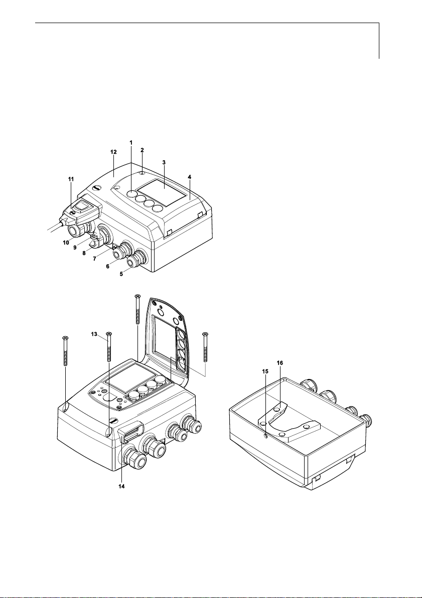
1.2.1 At a glance
1 Keys (only with optional display)
2 Service flap screw connection
(self-locking, 2x)
3 Display (optional)
4 Service flap
5 M 16 x 1.5 screw connection*,
e.g. analog outputs
6 M 16 x 1.5 screw connection*,
e.g. voltage supply
7 Earthing/PE connection
8 M 20 x 1.5 screw connection*,
e.g. relay R 3 and R 4
9 Eyelet for measuring point panel
10 M 20 x 1.5 screw connection*,
e.g. relay R 1 and R 2
11 Probe connector (testo 6610)
12 Upper part of housing
* Alternatively, NPT cable
couplings or M plug-in
connections are available
11
13 Housing screws
14 Socket for probe connector
15 Hole for fastening to rear panel
bracket (M3 x 6 screw)
16 Plastic bracket for assembly on
rear panel
Page 12

12
testo 6681 - 1.2 Product description
1.2.2 Usable probes
The testo 6681 humidity transmitter can be used with the following probes:
probe Article no. Characteristic
testo 6611 0555 6610-L11 Wall probe version; accuracy to ± 1 % RH;
testo 6612 0555 6610-L12 Duct probe version; accuracy to ± 1 % RH;
testo 6613 0555 6610-L13 Cable probe version; accuracy to ± 1 % RH;
testo 6614 0555 6610-L14 Heated cable probe version; accuracy to
testo 6615 0555 6610-L15 Trace humidity cable probe version;
testo 6617 0555 6610-L17 Cable with cover electrode monitoring probe
testo 6622 0555 6610-L22 Duct probe version; accuracy to ± 1 % RH;
testo 6623 0555 6610-L23 Cable probe version; accuracy to ± 1 % RH;
temperature range -20 °C to +70 °C/-4 to +158 °F
temperature range -30 °C to +150 °C/-22 to +302 °F
temperature range -40 °C to +180 °C/-40 to +356 °F
± 1.0 % RH; temperature range -40 °C to +180 °C/
-40 to +356 °F
accuracy ± 6 K at -60 °Ctd;
temperature range -40 °C to +120 °C/-40 to +248 °F
version; temperature range -40 °C to +180 °C/-40
to +356 °F
temperature range -30 °C to 120 °C/-22 to +248 °F
temperature range -30 °C to +120 °C/-22 to +248 °F
1.2.3 Display and keypad
The display option allows the testo 6681 humidity transmitter to be operated
via the display and four keys.
The LCD display consists of two 7-segment lines for displaying readings and
units and of an information line (for status messages, for example).
The brightness and contrast of the display and the background lighting
(permanent or off) can be changed via the user menu or the P2A software.
1.2.4 Service interface
Behind the service flap is the parameterizing socket (mini-DIN) as an
interface to the P2A software or Testo handheld instrument
(testo 400/testo 650).
Page 13
testo 6681 - 1.2 Product description
1.2.5 Relay board (option)
This has a floating switch capacity of 250 V AC/3 A. The switching limits and
hysteresis as well as the function as relay for the collective alarm can be set
via the display or the P2A software. Further features include:
• Function of changeover contacts (NC/NO contacts) freely selectable
• 12 terminals for a total of 4 relays.
If no relays are available, settings for monitoring limit values
or alarms can still be controlled via the display. The alarm
status will be shown on the display
Only have the transmitter wired and connected by authorized
personnel with the voltage disconnected.
1.2.6 Analog outputs
For analog outputs, the testo 6681 has either
13
• 2 or optionally 3 current outputs of 4 to 20 mA (2-wire)/0 to 20 mA (4-
wire)/4 to 20 mA (4-wire) or
• 2 or optionally 3 voltage outputs of 0 to 1 V/0 to 5 V/0 to 10 V (4-wire).
The transmitter can be ordered with a third analog output as an option.
In 2-wire operation, channel 1 is used for the supply. The two or optionally
three channels are galvanically isolated in both 2- and 4-wire operation.
Operation with the testo 6614 heated probe, the testo 6615
trace humidity probe, the relay and profibus options or with
the background lighting of the optional display are only
possible in 4-wire operation.
1.2.7 Parameters
The following parameters are displayed:
• Relative humidity in %RH (technical)
• Relative humidity in % WMO* (calculation according to the WMO
standard)
Page 14

14
testo 6681 - 1.2 Product description
• Temperature °C and °F
• Dewpoint or pressure dewpoint in °Ctd and °Ftd
• Absolute humidity in g/m³ and gr/ft³
• Degree of humidity in g/kg and gr/lb
• Enthalpy in kJ/kg and BTU/lb
• Psychrometer temperature in °Ctw and °Ftw
• Water vapour partial pressure in hPa and "H
• Water content in ppm
• Dewpoint of H
2O2
and % vol
vol
mixture in °Ctm and °Ftm.
* It is possible that condensation appears as of a displayed humidity
starting from 70 % and is shown on the display.
Calculated humidity variables correspond to the medium of
air. With other gases/gas compositions, deviations may
occur, e.g. with the enthalpy
1.2.8 Scaling
There are three types of min./max. values:
O
2
1 The measuring range
The maximum sensor performance is in this range. Values outside of
the measuring range are displayed via messages, for example.
Measuring range, see table (below).
2 Standard scaling
The output signals are assigned to this measuring range as standard:
- during delivery if no entries are made in the order code
- after exchanging the unit, the measuring range recorded in the
instrument is applied as standard.
The transmitter even retains its scaling with the voltage
disconnected.
Measuring range, see table (below).
3 The maximum settings for the manual scaling
- the values are not expressly given in the table. The maximum limits
can be calculated as follows:
Page 15

testo 6681 - 1.2 Product description
X = difference between MIN. and MAX. value of the standard scaling
(Max. value of standard) + (50 % of X)
(Min. value of standard) - (50 % of X)
- It is thus possible to scale beyond the measuring range, e.g. for the
adjustment of the scaling limits to standard values of a PLC.
Standard
Measuring
range
Physical
Parameter Unit probe
Temperature °C 6611 -20 +70 -20 +70
°F 6611 -4 +158 -4 +158
°C 6612 -30 +150 -30 +150
°F 6612 -22 +302 -22 +302
°C 6613, 6614, 6617 -40 +180 -40 +180
°F 6613, 6614, 6617 -40 +356 -40 +390
°C 6615 -40 +120 -40 +120
°F 6615 -40 +248 -40 +248
°C 6622, 6623 -30 +120 -30 +120
°F 6622, 6623 -22 +248 -22 +248
relative humidity % RH 0 +100 0 +100
WMO relative humidity % RH, 0 +100 0 +100
Dewpoint/pressure dewpoint °Ctd 6611 -80 +70 -80 +100
°Ftd 6611 -112 +158 -112 +212
°Ctd 6615 -60 +30 -80 +100
°Ftd 6615 -148 +212 -112 +212
Mixture dewpoint (H2O2) °Ctm -20 +100 -20 +100
°Ftm -4 +212 -4 +212
Absolute humidity g/m3 all probes 0 600 0 2000
gr/ft3 0 250 0 800
Degree of humidity g/kg all probes 0 13300 0 950 0
°Ctd
°Ftd
6612, 6613, 6614,
6617, 6622, 6623
6612, 6613, 6614,
6617, 6622, 6623
at 1013 hPa
MIN MAX MIN MAX
-20 +100 -80 +100
-112 +212 -112 +212
scaling
MUF
measuring
range
15
Page 16

16
testo 6681 - 1.2 Product description
Standard
Measuring
range
Physical
Parameter Unit probe
gr/lb 0 93000 0 66500
Enthalpy kJ/kg -40 99999 -40 8000
BTU/lb -18 43000 -18 3500
Psychrometer temperature °Ctw -40 100 -40 180
°Ftw -58 210 -40 356
Water content ppm vol H2O 0 99999 0 99999
% vol 0 100 0 100
Water vapour partial pressure hPa 0 1000 0 7000
inchH2O 0 400 0 2800
at 1013 hPa
MIN MAX MIN MAX
scaling
MUF
measuring
range
Page 17

testo 6681 - 1.2 Product description
1.2.9 Alarm handling
For upper and lower alarm limits, individual alarms as well as collective
alarms can be specified. If the collective alarm function is activated, an alarm
is triggered as soon as the alarm limit of an alarm is exceeded, if this alarm is
assigned to the collective alarm.
The testo 6681 monitors limit values using relays. If a reading is outside the
limit values, a relay to be specified by the user is switched.
If the reading reverts to more than a specified hysteresis below or above the
limit value, the alarm is cancelled.
In addition, information about the occurrence of error/status messages can
be provided by means of a collective alarm relay, see Chapter 1.5 Status,
warning and error messages.
If multiple alarm messages are activated at the same time,
the last alarm is shown. If the alarm is cancelled again, the
previous messages are no longer shown.
Example:
17
If the condensation of the probe begins, the "Condensation"
message appears on the display and the "Start" status
display. If the condensation is over, the status display
changes from "Start" to "End".
Page 18
18
testo 6681 - 1.3 Commissioning
1.3 Commissioning
1.3.1 Assembling the instrument
1.3.1.1 Wall mounting
(for testo 6611/6613/6614/6615/6617/6622/6623
probes)
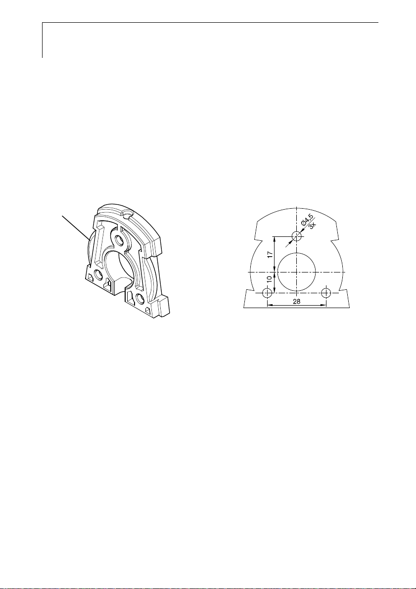
Attaching rear panel bracket
1
1 Remove locking screw (item (4) of drawing below) and detach rear
panel bracket from plastic bracket (item (2) of drawing below).
2 Hold rear panel bracket in assembly position and mark the three drill
holes.
3 Drill three holes (∅ 5 mm) and insert dowels where necessary.
4 Screw on rear panel bracket.
Remember that the clamping brackets (1)must face the wall.
Page 19
testo 6681 - 1.3 Commissioning
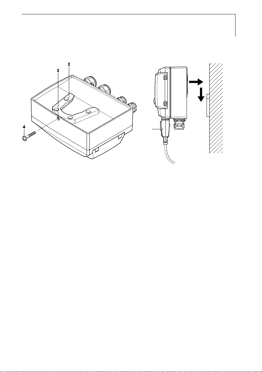
Fastening instrument to rear panel bracket
5
1 Slide plastic bracket (2) on the back of instrument onto rear panel
bracket until it engages (see arrows).
2 Insert screw (4) through hole (3) and screw into rear panel bracket.
3 Insert probe connector (5) into socket until it engages.
19
Page 20
20
testo 6681 - 1.3 Commissioning
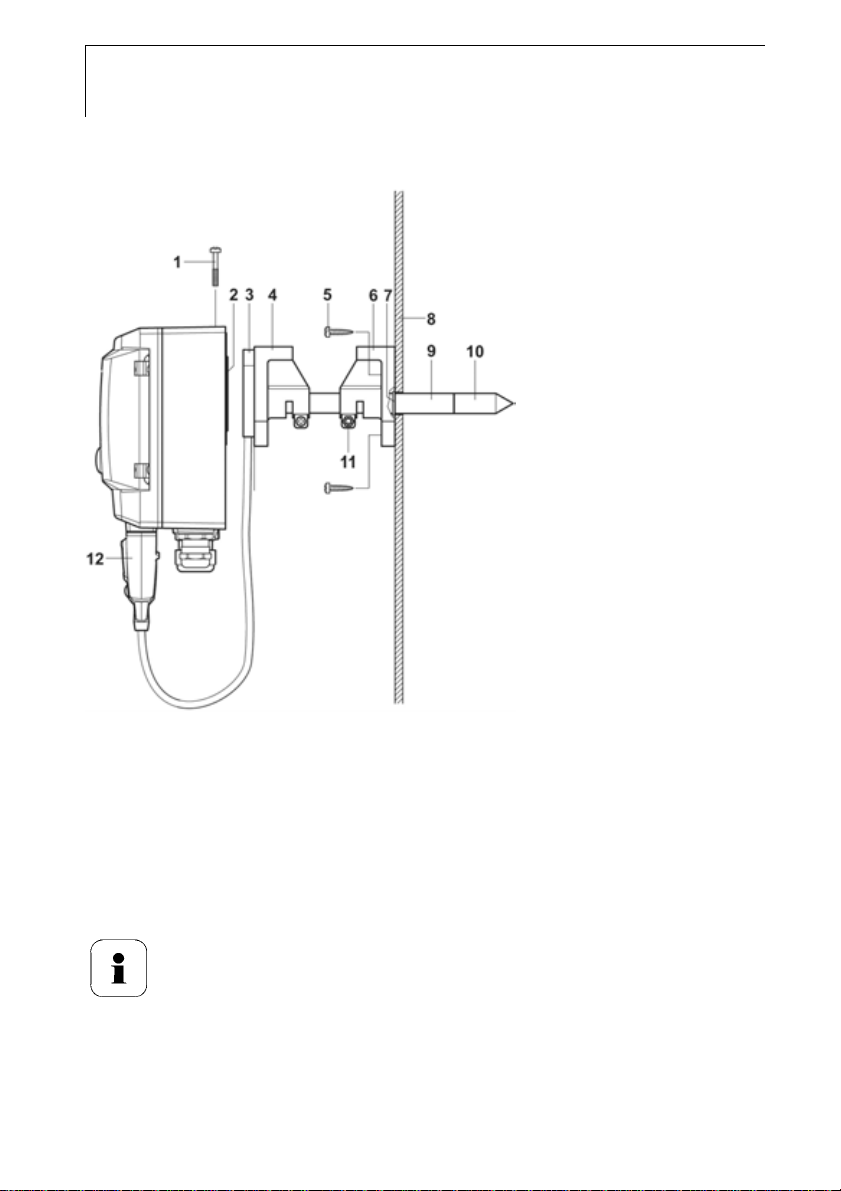
1.3.1.2 Duct mounting (for testo 6612 probes)
1 Hold wall/duct bracket (order no. 0554 6651) (6) against duct wall (8)
and mark drill holes for wall/duct bracket and probe shaft.
2 Drill a hole (∅ 12.5 mm) in the duct wall to feed through the probe
shaft.
3 Fasten wall/duct bracket (6) to duct wall with screws (5).
4 Push probe shaft (9) with filter (10) through the middle hole of the
mounting bracket.
The wall/duct bracket (6) has an O-ring (7) to seal it against
the duct. Feed the probe shaft (9) carefully through the
wall/duct bracket so that the O-ring is not damaged.
5 Fix the correct position of the probe shaft (9) with screw (11) and mark
(insert probe shaft as far as possible).
6 Slide plastic bracket (2) on the back of the transmitter onto bracket (3,
4) until it engages.
Page 21
testo 6681 - 1.3 Commissioning
Take the weight of the transmitter into account. Ensure that
the brackets (4, 6) are fastened securely.
7 Insert screw (1) through the hole on the top of the instrument and
screw into bracket (3).
8 Insert probe connector (12) into socket until it engages.
1.3.2 Connecting the instrument
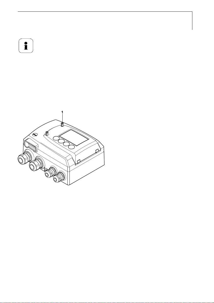
Opening the instrument
21
1 Loosen screw connection (1) of service flap and open the flap.
Page 22
22
testo 6681 - 1.3 Commissioning
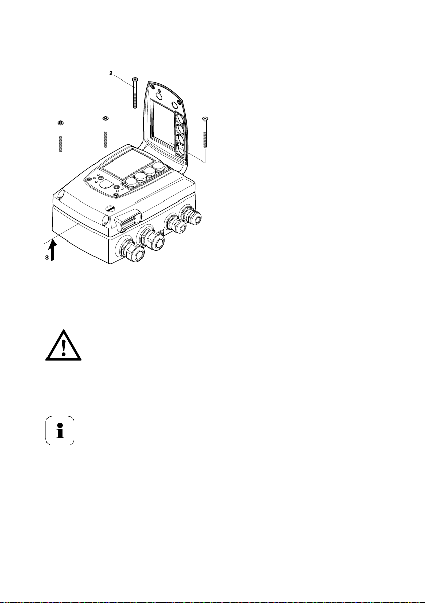
2 Loosen and remove housing screws (2).
3 Remove upper part of housing from lower part (3) and place on a
clean surface.
Warning!
Electrical voltage.
Danger of injury!
De-energize the mains connection before connecting the
transmitter!
Only have the transmitter wired and connected by authorized
personnel with the voltage disconnected.
Page 23
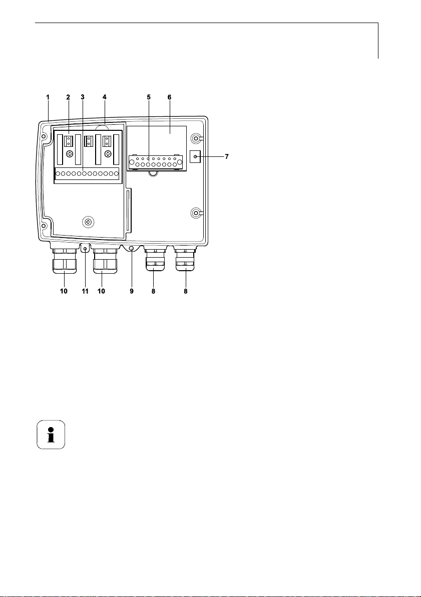
1.3.2.1 Overview of terminals
testo 6681 - 1.3 Commissioning
23
1 Lower part of housing
2 Relay board (option)
3 Relay terminals
4 Insulating trough for relay board
5 Terminal strip for voltage supply
and analog outputs
6 Terminal board
The following description of the terminals refer to this
overview and its numbering.
7 Earthing terminal (internal)
8 M 16 x 1.5 screw connection*
9 Earthing terminal (external)
10 M 20 x 1.5 scr ew connection*
11 Eyelet for measuring point panel
* Alternatively, NPT cable coupling
or M plug-in connection
Page 24
24
testo 6681 - 1.3 Commissioning
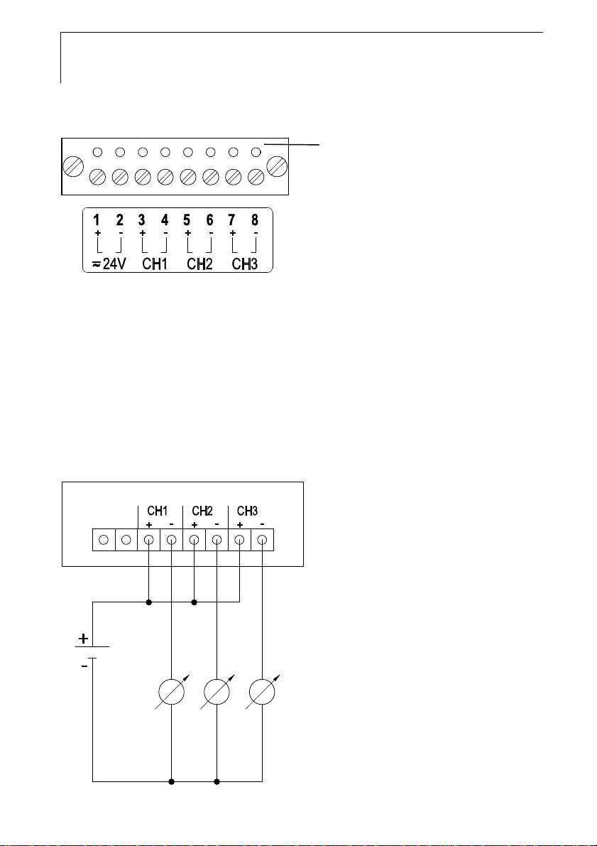
1.3.2.2 Connecting voltage supply and analog outputs
Terminal strip for voltage supply and
analog outputs, item (5) of Overview of
terminals, chapter 1.3.2.1.
1 Feed cable with voltage supply and analog signal lines through opened
M 16 x 1.5 screw connection (item (8) in Overview of terminals,
Chapter 1.3.2.1).
2 Strip the cable ends, clamp wire end ferrules on and screw down onto
voltage terminals.
3 Close M 16 x 1.5 screw connection (item (8) in Overview of terminals,
Chapter 1.3.2.1).
Wiring diagram for 2-wire system (4 - 20 mA)
12 to 30
0 V
2 or 3 channels
4 to 20 mA, max. load 100 to 750 Ω
Page 25
If the channels have to be galvanically isolated, a separate
mains unit must be used for each channel.
Wiring diagram for 4-wire system
(0 to 20 mA/4 to 20 mA/0 to 1 V/0 to 5 V/0 to 10 V)
CH1
20 to 30
V AC/DC
+
24V
-
+
CH2 CH3
-
+
-
-
+
+
-
0 V
2 or 3 channels
0 to 20 mA/
4 to 20 mA/
max. load per 500 Ω
0 to 1 V/0 to 5 V/0 to 10 V
testo 6681 - 1.3 Commissioning
25
Requirement for the connecting cable of the supply:
• Insulated with cross-section of at least 0.25 sq. mm.
• The supply line must be secured against exceeding 8 A.
• An OFF switch must be installed in an easily accessible
position close by and be marked as such.
1 Feed connection cables of the two, or optionally three, channels
through opened M 16 x 1.5 screw connection (item (8) in Overview of
terminals, chapter 1.3.2.1).
2 Strip the cable ends, clamp wire end ferrules on and screw to channel
terminals as shown in diagram.
3 Close M 16 x 1.5 screw connection (item (8) in Overview of terminals,
Chapter 1.3.2.1).
Page 26
26
testo 6681 - 1.3 Commissioning
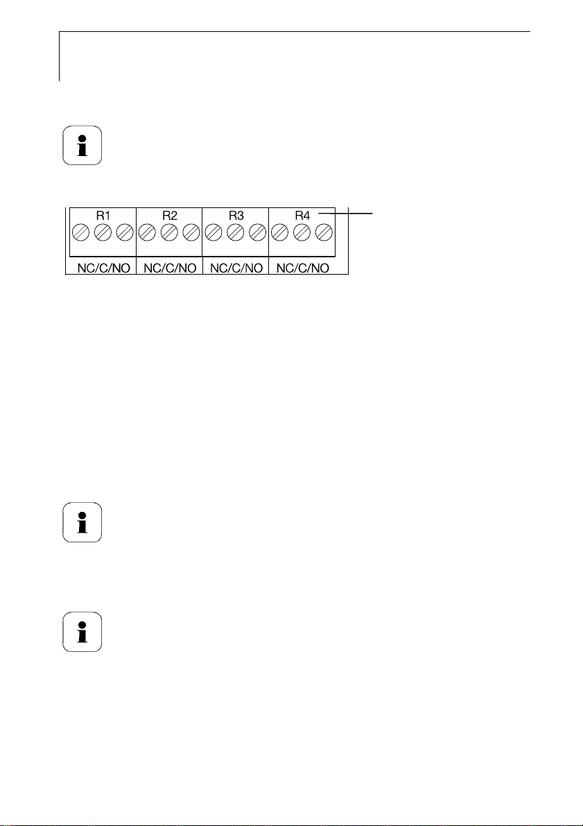
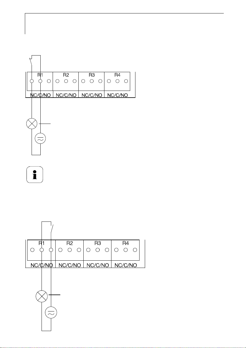
1.3.2.3 Connecting the relay outputs
Only have the transmitter wired and connected by authorized
personnel with the voltage disconnected.
Relay terminal strip, item (3)
of Overview of terminals,
chapter 1.3.2.1
There is the option of twelve terminals for a total of four relays. The
designations NC/C/NO (normally closed contact/root or pin/normally open
contact) are etched on the surface of the board.
Using PG screw connection
1 Feed connection cables for the relays through opened M 20 x 1.5
screw connection (item (10) of Overview of terminals, chapter 1.3.2.1).
2 Strip cable ends and clamp on wire end ferrules.
3 Connect relays according to chosen function (NC/NO) (see diagrams
below; relay 1 is shown as an example of a connection).
Using plug-in connections (optional)
Only insert or disconnect the plug-in connection when the
voltage is disconnected.
4 Clean the connector of the probe line and the coupling of any foreign
matter.
Do not disconnect the connector of the probe line from the
instrument for extended periods to protect against
contamination.
Page 27
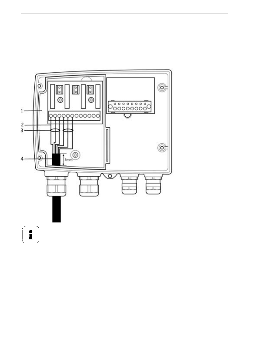
Connection note
testo 6681 - 1.3 Commissioning
27
• For the connection, a double-insulated mains cable
(sheathed cable) with a cross-section of at least 1.5 sq.
mm must be used.
• Cable connection (2) may not be routed in a loop within
the tray (1).
• It is recommended that you always tie 3 cores to one
another using a cable tie (3).
• The insulation of the cable must be fed at least 5 mm (4)
into the tray.
Page 28
28
(
)
testo 6681 - 1.3 Commissioning
Use of relay as NC contact (NC = normally closed)
Alarm/status light
(example of installation)
250 V AC/DC, 3 A
The busy light (alarm/status light) is permanently on until the
relay opens or the circuit is interrupted. This circuit can
therefore be used to monitor the functionality of the alarm
circuit, as a cable break, for instance, is indicated by the busy
light going off.
Use of relay as NO contact (NO = normally open)
Alarm/status light
example of installation
250 V AC/DC, 3 A
Page 29
testo 6681 - 1.3 Commissioning
The busy light (alarm/status light) only comes on when the
relay is switched (closed). Monitoring the functionality of the
alarm circuit is therefore not possible with this switching
operation.
5 Close M 20 x 1.5 screw connection (item (10) in Overview of terminals,
Chapter 1.3.2.1).
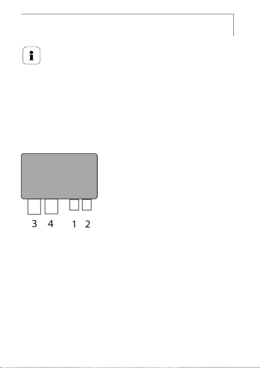
1.3.2.4 Plug-in connection option
As an option, the PG screw connections of the signal and supply lines can be
replaced with plug-in connections that are installed at the housing, see Fig. 1
and 2. The relay cabling occurs via standard cable entries and PG screw
connections, see Fig. 3 and 4.
Transmitter housing
29
Page 30
30
testo 6681 - 1.3 Commissioning
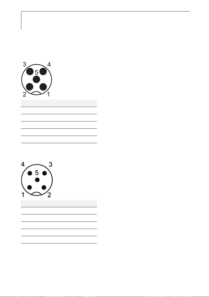
Plug-in connections for power supply and channels
M12 plug-in connection (5-pin) socket (1)
View of the plug-in connections in the installed state from outside
Pin Assignment.
1 V 24 2 V 24 +
3 + Ch 1
4 - Ch 1
5 PE
M12 plug-in connection (5-pin) connector (2)
Pin Assignment.
1 - Ch 2
2 + Ch 2
3 + Ch 3
4 - Ch 3
5 PE
Page 31

testo 6681 - 1.3 Commissioning
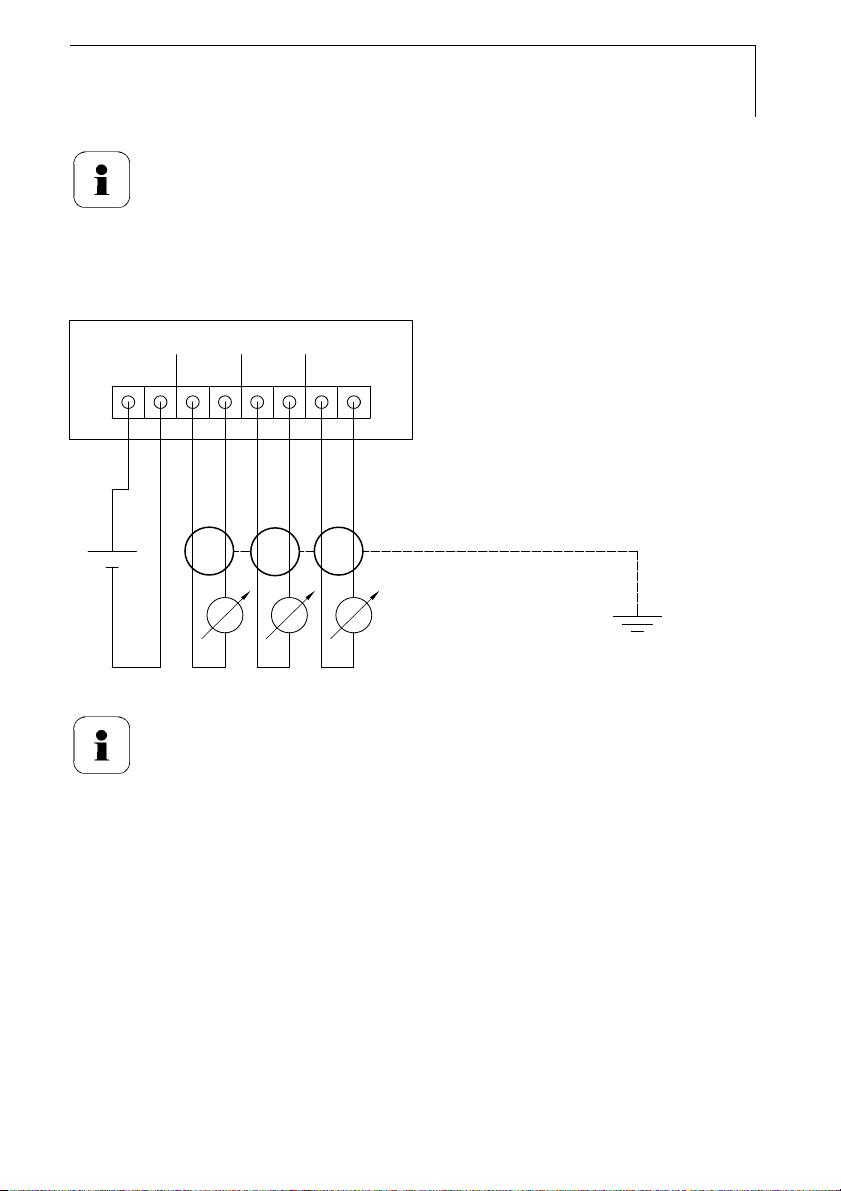
1.3.2.5 Creating the PE/earthing terminal
As the testo 6681 has a metal housing, we recommend that the instrument
be earthed. This can be done using the earthing terminal within the
instrument (1) or the earthing terminal outside of the instrument (2).
Only use the external earthing terminal in dry interiors.
31
Using the earthing terminal within the instrument
1 Guide PE line (yellow-green) (5) through the cable coupling (x) and fit
cable lug (8). Fix this to the side of the instrument (6) using M 5 screw
(3), washer (4) and snap ring (7) on the internal earthing terminal (1).
2 Place the other cable end on an appropriate (PE) earth conductor, e.g.
an earthing bar.
Using an earthing terminal outside of the instrument
1 Use shielded cable (5) with cable lug (8). Fix this using M 5 screw (3),
washer (4) and snap ring (7) on the external earthing terminal (2).
2 Place the other cable end on an appropriate (PE) earth conductor, e.g.
an earthing bar.
Page 32

32
testo 6681 - 1.3 Commissioning
1.3.2.6 Closing the instrument
1 Place upper part of instrument on top of lower part (see arrow) and fix
in place with housing screws (1).
2 Close the service flap and tighten screws (2).
Page 33

testo 6681 - 1.3 Commissioning
1.3.3 Adjusting the instrument
The testo adjusting concept allows the entire signal chain from the sensor
signal (probe) and the digital signal (within the transmitter) through to the
analog signal (transmitter output signal) to be adjusted (see diagram).
1-point adjustment 2-point adjustment Analog adjustment
33
Adjustment via
- testo 400/650 handheld
instrument with
adjustment adapter
- P2A software
- User menu
Adjustment via
- Adjustment keys (1, 2)
- P2A software
Adjustment using a precise
multimeter and
transmission of analog
reference value in
- P2A software or
- User menu
Either the 1-point adjustment or the 2-point adjustment is suitable for
adjusting the sensor signal - digital signal chain.
The testo 6681 transmitter has digital probes whose adjustment information
is stored in the probes' internal memory. Both 1-point and 2-point
adjustments can thus be carried out on another testo 6681 (e.g. in the
calibration laboratory).
Page 34

34
testo 6681 - 1.3 Commissioning
1.3.3.1 Overview: Adjustment keys and test contacts
1 Status LED
2 Contact ch. 1 +
3 Contact ch. 1 4 Adjust key 11.3 %
5 Service interface
6 Adjust key 75,3 %
7 Contact ch. 2 +
8 Contact ch. 2 -
1.3.3.2 1-point adjustment (offset)
In the 1-point adjustment, the reading at the working point is raised to the
reference value so that there is no longer any deviation in the working point.
The reference condition can be measured using a precise handhel d
instrument (e.g. testo 400/650 with precision humidity probe) or be created in
an air conditioning cabinet.
Deviation
WP
Working range
after
before
e.g. scale = 0 - 100 % RH
The advantage of the 1-point adjustment is the good measuring result in the
working range. But the further away the measurement is from the working
point, the greater the deviation can become. The 1-point adjustment should
therefore only be used for a relatively narrow measuring range (working
Page 35

testo 6681 - 1.3 Commissioning
range), e.g. clean room applications, air conditioning applications for storage
and similar.
The 1-point adjustment can be performed
• via the user menu (see Chapter 1.4.6.9) or
• via the P2A software (see Chapter 3) or
• directly by means of a Testo handheld instrument (testo 400/650) (se e
description of how to proceed below).
Please note that the 1-point adjustment is generally
performed on the basis of the % RH and °C/°F parameters.
Adjusting testo 6681 using Testo handheld instrument
The service flap is open, a testo 400/650 handheld instrument with a
precision humidity probe is ready.
5
1
2
3
4
35
1 Connect Testo handheld instrument 400/650 (1) with connected
humidity reference probe (3) (order no. reference set 0699 3656/20) to
Page 36

36
testo 6681 - 1.3 Commissioning
the service interface (5) of the testo 6681 via the adjustment adapter
(2) (connected to the probe socket 1 of the handheld instrument).
2 Expose the humidity probe (4) of the testo 6681 and the reference
probe (3) to the same reference conditions (e.g. in the humidity
generator) and allow climatic conditions to equalize.
3 Switch on the testo 400/650. The two-part display of the handheld
instrument will show the values of the transmitter on the left, and the
values of the reference probe on the right. The humidity and
temperature values are adjusted to the reference probe using the
Probe > Probe Adjustment menu item on the testo 400/650.
The 1-point adjustment is performed for both the humidity and the
temperature.
4 Disconnect the adapter (2) from the service interface (5).
5 Close the service flap.
1.3.3.3 2-point adjustment
With the 2-point adjustment, the parameter is adjusted to the reference value
at the two standard adjustment points 11.3 % RH and 75.3 % RH. The
reference conditions are created either by using Testo humidity adjustment
set (order no. 0554 0660) or in the humidity generator.
Deviation
after
before
In the 2-point adjustment, the deviations between the reading and the
nominal value are minimized across the entire measuring range. The 2-point
adjustment is therefore recommended for large working ranges, e.g. in drying
processes.
The 2-point adjustment can be performed
• via P2A software (see Chapter 3) or
• using the adjustment keys under the service flap, see description of
how to proceed below.
Page 37

testo 6681 - 1.3 Commissioning
Adjustment with the standard Testo adjustment salt pots is
not suitable for the testo 6614 (heated for high-humidity
applications) and testo 6615 (trace humidity) probes. The
reference conditions should be generated in a humidity
generator to adjust these probes.
In addition, these probes can also be adjusted at a third
adjustment point by Testo Service.
• testo 6614: third adjustment point at 90 % RH
• testo 6615: third adjustment point at -40 °Ctd/-40 °Ftd
Adjusting testo 6681 using adjustment keys
37
or
11.3 %
RH
75.3 %
RH
11.3 %
RH
75.3 %
RH
(salt pots) (humidity generator)
Page 38

38
testo 6681 - 1.3 Commissioning
The service flap of the testo 6681 is open.
1 Expose the humidity probe of the testo 6681 to the reference condition
of 11.3 % RH for at least 1.5 hours at 25 °C.
2 After this equalization period, press the 11.3 % adjustment key (4) for
at least 10 seconds with something like a ball-point pen that is not too
sharp. The LED (1) flashes when the adjustment process begins. At
the same time, the 2-point adjustment 11.3 % status message
appears on the display
Completion of the adjustment is signalled by the LED (1) coming on
permanently and the Probe reset status message is shown.
Carry out the adjustment analogously for the reference condition
75.3 % RH. Press on the 75.3 % RH adjustment key (6) to do this.
3 Close the service flap.
1.3.3.4 Analog output adjustment
The purpose of adjusting the analog outputs is to adjust the signal chain from
the digital signal (within the transmitter) to the analog outputs. The signal type
that was appointed for the transmitter is adjusted respectively for each
channel (e.g. 4 to 20 mA or 0 to 1 V, etc.).
1 Status LED
2 Contact ch. 1 +
3 Contact ch. 1 4 Adjust key 11.3 %
5 Service interface
6 Adjust key 75,3 %
7 Contact ch. 2 +
8 Contact ch. 2 -
Page 39

testo 6681 - 1.3 Commissioning
Analog outputs 1 and 2 adjusted
A precise multimeter (minimum resolution of 6.5 digits, accuracy of
100 mA, e.g. Agilent 34401A) is available.
If only a simple multimeter is available, the analog outputs
may not be adjusted.
The service flap is open.
1 Connect the inputs of the multimeter with the contacts (2) and (3) for
channel 1 or with contacts (7) and (8) for channel 2.
2 Transfer the reference analog value measured with the multimeter to
the P2A software (see Chapter 3) or enter it via the user menu (see
Chapter 1.4.6.9).
3 Disconnect connections between multimeter and contacts of the
testo 6681 and close service flap.
Adjusting analog output 3 (optional)
If the optional third analog output is to be adjusted, a cable
connection to measure the analog value must be installed.
Do this by proceeding as follows:
39
1 Open transmitter (see Chapter 1.3.2).
2 Connect measuring cable to the terminals of the third analog output
and guide through the cable coupling and out of the transmitter.
3 Reassemble upper part of transmitter (see Chapter 1.3.2.6).
4 Connect cable ends to the inputs of the multimeter.
5 Transfer the reference analog value measured with the multimeter to
the P2A software (see Chapter 3) or enter it via the user menu (see
Chapter 1.4.6.9).
6 Remove the upper part of the transmitter, detach the cable
connections for the adjustment of the 3rd analog output and
reassemble the transmitter.
Page 40

40
testo 6681 - 1.3 Commissioning
1.3.3.5 High-humidity adjustment for testo 6614
Mollier diagram
e.g. 73 % RH
"Microclimate"
sensor conditions
After heating
High-humidity process
conditions
Mist
With the testo 6614, the rear of the Testo humidity sensor is heated, creating
a microclimate around the sensor (within the filter) that is constantly 5 K
warmer than the actual process conditions. As can be seen in the Mollier
diagram, this reduces the relative humidity at the sensor from around
100 % RH to a lower value, e.g. 73 % RH. In this range, the reaction time of
the sensor is noticeably shorter than in the condensation range and the risk
of the sensor corroding is also reduced. Using the separate temperature
probe, the testo 6681 transmitter compensates the microclimate conditions
and displays the process readings.
100 % RH
The reference conditions (11.3 % RH and 75.3 % RH) for the
2-point adjustment of the testo 6614 should be generated in a
humidity generator, as humidity adjustment sets cannot be
used due to the heat generated. The adjustment can also be
carried out at a third adjustment point (90 % RH) by Testo
Service so that optimum accuracy is also achieved in the high
humidity ranges.
Page 41

testo 6681 - 1.3 Commissioning
1.3.3.6 Self adjustment of testo 6615 trace humidity
probe
Conventional trace humidity probes show a steep rise in measuring
uncertainty at low humidities. In the testo 6615 trace humidity probe, these
measuring uncertainties are corrected by means of an automatic selfadjustment process. This means that extremely accurate measuring results
are also attained to -60 °Ctd.
To this end, a temperature sensor is fitted on the back of the testo 6615
which is used as a heater. A humidity and temperature value pair is taken in
both the unheated and heated state. The deviation of the probe obtained
from these pairs of values is automatically corrected.
testo 6615:
testo 6615:
probe
Fühler-
behaviour
verhalten
"Duration of heating phase"
Parameter
parameter
„Dauer Heizphase“
"Self-adjustment cycle time"
„Zykluszeit Selbstabgleich“
41
Analog
Analog-
output °Ctd/
Ausgang
°Ftd
°Ctpd/
°Ftpd
Heizphase
Heating phase
Heating phase
Heizphase
The heating time and storing of cycles can be edited in the P2A software; for
example, they can be deactivated by setting the two parameters to "0".
Page 42

42
testo 6681 - 1.4 Operation
Important:
• Deactivating the adjustment function of the testo 6615
will reduce measuring accuracy and should therefore
be restricted to the shortest possible length of time.
• During the heating phase, the relay and analog
outputs, the display value and output value are
"frozen", see diagram above. Self-adjustment active
is shown in the display until it has finished. The factory
setting for the heating phase is 15 minutes per day.
• In the factory setting, a third adjustment point (-
40 °Ctd) is approached for the testo 6615 in addition to
the 2-point adjustment.
This special adjustment can be performed again by
your Testo Service team if necessary.
1.4 Operation
1.4.1 Relationship between user menu and
mini-DIN socket is active
The testo 6681 can be parameterized using either the user menu or the P2A
software (see Chapter 3).
The testo 6681 humidity transmitter can only be operated via
the display and keypad if the display option is available.
If the testo 6681 is connected to the P2A software, the user
menu is blocked for the duration of the communication. The
message Service plug is shown in the display of the
testo 6681. As soon as the P2A software is disconnected, the
user menu is accessible again.
1.4.2 Key cover
To prevent unauthorized operation of the keys, the standard key frame can
be replaced with a key cover (see below).
Page 43

testo 6681 - 1.4 Operation
If the key cover has been assembled, the service flap must be opened for
operation, see Section Opening the instrument, Chapter 1.3.2.
Attaching the key cover
43
The service flap is open, see Opening the instrument, Chapter 1.3.2.
1 Undo screws (3) and remove key frame (2).
2 Insert key cover (1) into service flap and tighten screws (3).
3 Close and screw down the service flap.
Page 44

44
testo 6681 - 1.4 Operation
1.4.3 Password protection
The user menu can be protected with a four-digit numerical code (see Editing
Main Menu Settings, Chapter 1.4.6.5) so that access to the user menu is
denied to unauthorized persons not familiar with this numerical code.
If the password protection is not to be used, the numerical code "0000" must
be entered. This is also the status upon delivery.
1.4.4 Structure of user menu
At the main menu level, the user menu comprises the following:
• Main menu of channel 1
• Main menu of channel 2
• Main menu of channel 3 (if this option is available)
• Main Menu Alarm
• Editing Settings main menu
• Analysis main menu
• Main Menu Messages
• Ident main menu
• Adjustment main menu
• Reset main menu
19.3 °C
57.8 % RH
-4.1 °Ctd
Channel 1 display
Channel 2 display
Channel 3 display or for messages
Page 45

testo 6681 - 1.4 Operation
Four keys enable the user to navigate/scroll through the menus and
enter/amend values and settings:
Key Function/description
SET
ESC
X
S
- In Measuring Mode: changes to parameterization
- In Parameterizing Mode: confirms a selection or setting
- Leaves a menu (without modifying any settings)
- Selecting: scrolls through menus (downwards) or selectable
alternatives
- Editing: changes to next digit (to the right)
- Selecting: scrolls through menus (upwards) or selectable alternatives
- Editing: increases the value of the current digit by 1
45
Page 46

46
testo 6681 - 1.4 Operation
1.4.5 Overview of the testo 6681 user menu
Page 47

testo 6681 - 1.4 Operation
47
Page 48

48
testo 6681 - 1.4 Operation
1.4.6 The individual main menus
1.4.6.1 Editing Main Menu Channel 1
An overview is given in Overview of the testo 6681 user menu, Chapter 1.4.5.
You can perform basic settings for channel 1.
1 In Measuring Mode, press SET, select Main Menu Channel 1 using X
or S and confirm selection with SET.
One of the following parameters can now be selected using X or S, after
which the selection must be confirmed with SET:
• Channel 1 unit
The parameter for this channel is selected.
Selection: % RH, °C, °F, °Ctd, °Ftd, g/m³, gr/ft³, g/kg, gr/lb, kJ/kg,
BTU/lb, °Ctw, °Ftw, "H2O, hPa, ppm
Edit/select parameter with X or S, confirm with SET or abort input
with ESC.
• Scale minimum for channel 1
The lower scale limit is edited;
Unit as selected above (example: 4 mA = 0 % RH).
Editing the value: Scroll one digit to the right using X, increase value
of digit by 1 using S. Confirm with SET or abort entry with ESC.
• Scale maximum for channel 1
The upper scale limit is edited;
Unit as selected above (example: 20 mA = 100 % RH).
Editing the value: Scroll one digit to the right using X, increase value
of digit by 1 using S. Confirm with SET or abort entry with ESC.
• Signal delay ("Damping") for channel 1
The analog signal can be delayed("Damping"); a time constant is
selected for this (1 = no delay; 15 = longest delay).
Edit/select parameter using X or S, confirm with SET or cancel entry
via ESC.
2 Continue to Main Menu Channel 2 using X or S or return to
Measuring Mode by pressing ESC.
, % Vol, °Ctm, °Ftm.
vol
1.4.6.2 Editing main menu of channel 2
See channel 1.
1.4.6.3 Editing main menu of channel 3 (if this option is
available)
See channel 1.
Page 49

testo 6681 - 1.4 Operation
1.4.6.4 Editing Main Menu Alarm
With the alarm, the relays, available as options, are programmed. In addition,
the alarm statuses are shown on the display (top right) (even without
relays).You can choose whether the alarm is to be used to monitor limit
values or as a collective alarm. If an alarm is to be used to monitor limit
values, you can choose between monitoring the minimum or maximum value
and set a limit value and hysteresis for each alarm.
1 In Measuring Mode, press SET, select Main Menu Alarm using X or
S and confirm selection with SET.
Four alarms can be parameterized.
2 Select Alarm x using X or S and confirm selection with SET.
Using alarm to monitor limit values
Monitoring minimum Monitoring maximum
Hysteresis Hysteresis
On On
NO contact
Off Off
49
On On
Off
Limit value Limit value
NC contact
Off
Cannel 2
e.g. °C
3 Select Channel x (e.g. "Channel 1") using X or S and confirm
selection with SET.
4 Select Max control or Min control with X or S (see graphic).
5 Press SET and edit limit value and hysteresis: Scroll one digit to the
right using X, increase value of digit by 1 using S. Confirm with SET
or abort entry with ESC.
6 Return to Channel x by pressing ESC.
7 Return to Alarm x by pressing ESC.
8 Change to the other relays using X or S and perform settings in the
same way.
Page 50

50
testo 6681 - 1.4 Operation
Using alarm as collective alarm or not using it at all
If the collective alarm is assigned to an alarm, the relay is switched as soon
as (at least) one of the warning or error messages of the testo 6681
transmitter (or the connected testo 6610 probe) is activated.
Note:
The messages affecting the collective alarm can only be
selected in the P2A software, see Chapter 3.
Alarm is selected (see previous steps 1 and 2).
1 Specify with X or S whether Alarm x is to be used as the Alarm
relay or is not to be used. Confirm selection with SET and return to
Alarm x.
2 Change to another alarm using X or S and perform settings in the
same way.
3 Continue to Main Menu Settings using X or S or return to Measuring
Mode by pressing ESC.
1.4.6.5 Editing Main Menu Settings
You can edit instrument settings and other settings.
▪ In Measuring Mode, press SET, select Main Menu Settings usi ng X
or S and confirm selection with SET.
You can edit settings for:
• Display
• Language
• H
• Absolute pressure unit
• Absolute pressure
• Code
proportion by weight entry (optional with 3rd analog output)
2O2
Unit: %
Selection: bar, psi, mPa, hPa
Unit as selected above.
Editing display settings
You can set the brightness and contrast of the display.
1 Select Display Settings using X or S and confirm selection with
SET.
Page 51

testo 6681 - 1.4 Operation
2 Select Backlight or Contrast using X or S and confirm selection with
SET.
One of the following parameters can now be selected using X or S, after
which the selection must be confirmed with SET:
• Backlight
The display illumination is changed.
Edit/select parameter with X or S, confirm with SET or abort input
with ESC (the effect of the change in parameter can be seen during
input).
• Contrast
The brightness difference between the display background and the
displayed values is changed.
Edit/select parameter with X or S, confirm with SET or abort input
with ESC (the effect of the change in parameter can be seen during
input).
• Backlight on 24 h
Using X or S select On or Off and confirm with SET.
Off: The display light switches off automatically if no button was
pressed for 10 seconds.
On: The display light is activated
3 Go back to Display Settings by pressing ESC and continue to
Language using X or S.
51
Selecting language
You can select the language for the plain text line in the display.
▪ Press SET, select required langua ge with X or S, confirm selection
with SET and return to Language.
Only choose a language that you can understand well.
Editing H
This menu is only used to parameterize humidity measurements in H
atmospheres (e.g. in sterilization processes) and determines whether °Ctm
or °Ftm is the output parameter.
1 Select H
with SET.
proportion by weight (optional with 3rd analog output)
2O2
Weight Proportion using X or S and confirm selection
2O2
2O2
Page 52

52
testo 6681 - 1.4 Operation
The selection H2O2 Water or H2O2 Vapour in the submenu describes
whether H
2O2
in the process.
is created through evaporation or is actively evaporated
2 Select H
Water or H2O2Vapour using X or S and confirm with
2O2
SET.
3 Editing proportion by weight of H
in % (% H2O2 proportion by
2O2
weight in the liquid end solution): Scroll one digit to the right using X,
increase value of digit by 1 using S. Confirm with SET or abort entry
with ESC.
4 Go back to H
by pressing ESC and continue to Absolute pressure
2O2
unit using X or S.
Selecting absolute pressure unit (Abs. pressure unit)
This parameter determines the humidity variables, atmospheric dewpoint
(°CtA, °FtA), relative humidity (g/kg or gr/lb) and water content (ppm
or %
vol
vol).
1 Press SET, select desired unit (selection: bar, psi, mPa, hPa) using X
or S confirm selection with SET or cancel with ESC.
2 Continue to Absolute Pressure with X or S.
Editing absolute pressure(Abs. pressure value)
You can set a value for the process absolute pressure.
1 Using X or S, select Abs. pressure value and confirm selection with
SET.
The absolute pressure is displayed.
2 Scroll one digit to the right using X, increase value of digit by 1 using
S. Confirm with SET or abort entry with ESC.
3 Press SET and return to Abs. pressure value
4 Return to Main Menu Settings by pressing ESC.
5 Continue to Main Menu Analysis using X or S or return to Measuring
Mode by pressing ESC.
Editing code settings
You can set the access code (password).
Page 53

testo 6681 - 1.4 Operation
If a code other than "0000" (factory setting) is set, the
transmitter can only be operated once this code has been
entered via the menu.
1 Select Code using X or S and confirm selection with SET.
2 Scroll one digit to the right using X, increase value of digit by 1 using
S. Confirm with SET or abort entry with ESC.
3 Return to Code by pressing ESC.
1.4.6.6 Editing Analysis main menu
You can test the functionality of analog and relay outputs. In addition, you
can read off the minimum and maximum readings (since the last voltage
supply or reset of the min./max. values
Testing functionality of analog outputs
This function affects the analog outputs directly, not only the
test contacts.
1 In Measuring Mode, press SET, select Main Menu Analysis using X
or S and confirm selection with SET.
Test Analog Output is shown.
).
53
2 Press SET, choose between Analog Output 1, 2, 3 with X or S.
3 Press SET, scroll one digit to the right using X, increase value of digit
by 1 using S. Any analog output value can be predefined, e.g. for an
analog output of 4 to 20 mA, the value "6.0 mA". Confirm with SET or
abort entry with ESC.
4 Accept setting by pressing SET and test with multimeter (minimum
requirement: resolution of 6.5 digits, accuracy of 100 nA):
Analog output 1 or 2: via test contacts under service flap, see diagram.
Page 54

54
testo 6681 - 1.4 Operation
1 Channel 1 test
contacts
2 Service interface
3 Channel 2 test
contacts
4 Ends of channel 3
cables
5 Multimeter
Analog output 3: Connect measuring cables to terminals for channel 3,
guide measuring cables out of housing and perform measurement
outside of the transmitter, see diagram.
5 Return to Test Analog Output using ESC and continue to Test Relay
Output using X or S.
Testing functionality of relay outputs
1 Press SET, choose between Alarm 1, 2, 3, 4 with X or S.
2 Press SET.
The relay can now be tested. You can choose between OFF and ON
using X or S. If ON is chosen, the NO contact is closed, the NC
contact opened. If OFF is chosen, the NC contact is closed, the NO
contact opened.
3 To test, route a measuring cable from the relay terminals (see
Chapter 1.3.2.3) out of the transmitter to a multimeter (resistance
measurement) or continuity tester.
4 Go back to Test Relay Output by pressing either SET (starts relay
test) or ESC (exits the menu without relay test).
Reading off min./max. values of channels
To reset the max./min. values, see Chapter 1.4.6.10 Editing
Reset main menu
1 Read off the min./max. values of the three channels by pressing X or
S one after the other and return to Main Menu Analysis using ESC.
2 Continue to Main Menu Message using X or S or return to
Measuring Mode by pressing ESC.
Page 55

testo 6681 - 1.4 Operation
1.4.6.7 Editing Message main menu
Messages can be confirmed/acknowledged, the last messages can be called
up and the display of the messages can be switched on or off.
Operating hours at the time of
message
Message number/number of messages
present
Example: "4/7" refers to the fourth of
seven messages
Message text
348
4/7
Scaling changed
Using the P2A software (see Chapter 3) you can predefine
which of the messages are to be shown in the display.
h
55
1 In Measuring Mode, press SET, select Main Menu Message using X
or S and confirm selection with SET.
2 Confirm Confirm message using SET.
3 Select Last messages using X or S and confirm with SET.
4 Scroll between the messages recorded so far using X or S and press
ESC to return to Last messages.
5 Continue to Display of message with X or S.
ON: Measurements are shown on the display in Measuring Mode.
OFF: No messages shown on display.
6 Select ON or OFF using X or S and confirm selection with SET.
7 Return to Main Menu Message by pressing ESC.
8 Continue to Main Menu Ident using X or S or return to Measuring
Mode by pressing ESC.
An overview of the messages can be found in
Chapter 1.5 Status, warning and error messages.
Page 56

56
testo 6681 - 1.4 Operation
1.4.6.8 Calling up Main Menu Ident
6681
Instruments or probe type
2.01
Serial
The serial numbers of the transmitter and probe can be read off.
1 In Measuring Mode, press SET, select Main Menu Ident using X or S
and confirm selection with SET.
The type, firmware version and serial number of the transmitter are
displayed.
2 Press ESC to return to the Main Menu Ident or read off the type,
firmware version and serial number of the probe using X or S and
then press X or S to return to the Main Menu Ident.
3 Continue to Main Menu Adjust using X or S or return to Measuring
Mode by pressing ESC.
Firmware version
Serial number
1.4.6.9 Editing Adjust main menu
A reference value can be entered for both relative humidity (RH) and
temperature (°C/°F) for the 1-point adjustment. Please refer to the description
in Chapter 1.3.3.2.
In addition, the analog outputs can be adjusted. See Chapter 1.3.3.4 for
instructions on how to do this.
The 2-point adjustment cannot be performed via the user
menu. This is done using the adjustment buttons or P2A
software, see Chapter 1.3.3.3 or Chapter 3.
Page 57

testo 6681 - 1.4 Operation
Enter reference value for 1-point adjustment
Please also refer to Chapter 1.3.3.2.
1 In Measuring Mode, press SET, select Main Menu Adjust using X or
S and confirm selection with SET.
Reference value % RH is displayed.
2 Press SET, edit value: Scroll one digit to the right using X, increase
value of digit by 1 using S. Confirm with SET or cancel entry with
ESC.
3 Continue to Reference value temp with X or S.
4 Press SET and Reference value °C is displayed.
5 Press SET, edit value: Scroll one digit to the right using X, increase
value of digit by 1 using S. Confirm with SET or abort entry with ESC.
6 Continue to Reference value °F with X or S.
7 Press SET, edit value: Scroll one digit to the right using X, increase
value of digit by 1 using S. Confirm with SET or abort entry with ESC.
8 Continue to Analog Adj. Ch. 1 with X or S.
9 Continue with the adjustment of the analog outputs (see below, step 2)
or press ESC to return to Main Menu Adjustment.
10 Continue to Main Menu Reset using X or S or return to Measuring
Mode by pressing ESC.
57
Performing analog adjustment
Please refer to Chapter 1.3.3.4.
1 In Measuring Mode, press SET, select Main Menu Adjust using X or
S and confirm selection with SET.
Each channel is adjusted at three points in the analog range
(at 10 %; 50 %; 90°% of the analog scale).
2 Select Analog Adj. Ch. 1 using X or S and confirm with SET.
3 Select Adj. Point 1 using X or S.
Page 58

58
testo 6681 - 1.4 Operation
4 Press SET. Read off multimeter display (e.g. 5.601 mA) and enter this
value in the user menu. Do this by scrolling one digit to the right using
X and increasing the value of digit by 1 using S. Confirm with SET or
abort entry with ESC.
5 Select Adj. Point 2 using X or S.
6 Press SET. Read off multimeter display (e.g. 12,001 mA) and enter
this value in the user menu. Do this by scrolling one digit to the right
using X and increasing the value of digit by 1 using S. Confirm with
SET or abort entry with ESC.
7 Select Adj. Point 3 using X or S.
8 Press SET. Read off multimeter display (e.g. 18,401 mA) and enter
this value in the user menu. Do this by scrolling one digit to the right
using X and increasing the value of digit by 1 using S. Confirm with
SET or abort entry with ESC.
9 Continue to Analog Adj. Ch. 2 or 3 with X or S (repeat steps 3 to 8).
10 Return to Main Menu Adjust by pressing ESC.
11 Continue to Main Menu Reset using X or S or return to Measuring
Mode by pressing ESC.
Page 59

testo 6681 - 1.4 Operation
1.4.6.10 Editing Reset main menu
You can reset the factory settings for the following:
• Instrument
• Sensor/probe
• Min./max. values
Resetting to the factory settings means resetting to the order
specification, i.e. the specific condition at the time of supply to
1 In Measuring Mode, press SET, select Main Menu Reset using X or
S and confirm selection with SET.
Reset device to factory settings is displayed.
2 Select the setting to be reset using X or S and confirm selection with
SET.
Reset Completed is displayed.
3 Press ESC or SET to return to reset setting and press ESC to return to
Main Menu Reset.
4 Continue to Main Menu Channel 1 using X or S or return to
Measuring Mode by pressing ESC.
the customer.
59
Page 60

60
testo 6681 - 1.5 Status, warning and error messages
1.5 Status, warning and error
messages
To achieve optimum operational reliability (machine
availability), the transmitter provides the following via the user
menu (see Chapter 1.4) or the P2A software (see Chapter 3):
• Status messages,
• Warning messages and
• Error messages
for either the testo 6681 or the connected testo 661x probe
as applicable.
All messages are stored in the transmitter with an operating
hours stamp. Use the user menu (see Chapter 1.4.6.7) or
P2A software (see Chapter 3) to view the message history.
In the transmitter, the last 180 messages are stored in a ring
memory, but there is no restriction in the P2A software.
1.5.1 Status messages
Status messages show the current operating mode of the testo 6681.
Message Display Description
00300 New limit value The limit value has been changed or shifted
00301 Scaling changed The scaling has been changed
00500 Transmitter reset: The transmitter is reset to the factory settings
and is restarted.
0052F Reset Min/Max Resets all saved Min/Max values for all channels
02506 Probe co nnection A probe has been connected
01D19 Service plug The Mini-DIN socket is connected to: the USB
00307 User Setting Change User Setting Change: General settings were
02d07 Probe d isconnected No probe is connected
adapter for P2A software, the adjustment
adapter or the service plug (is not recorded/no
number)
changed for the transmitter.
Page 61

testo 6681 - 1.5 Status, warning and error messages
Message Display Description
02104 Analog out adjust An analog adjustment has been made
02101 1-point adjustment A 1-point adjustment is performed.
02102 2-point adjustment
11,3%
02103 2-point adjustment
75.3%
02105 Self-ad justment active For testo 6615 probe only: The probe performs
02518 Probe reset Probe reset: The probe performs a reset
As part of the 2-point adjustment, an adjustment
is performed at 11.3 % RH
As part of the 2-point adjustment, an adjustment
is performed at 75.3 % RH
an automatic self-adjustment
1.5.2 Warning messages
Warning messages show an early warning or a current malfunction which
may negatively impact measuring.
Message Display Cause Remedying of fault
02101 2-point adjustment
drift*
00E00 T ambient high** The ambient temperature
00E01 T ambient low** The ambient temperature is
00E02 Supply voltage
low**
In the 2-point adjustment,
corrections repeatedly
occur in the same direction;
this may indicate a sensor
drift
exceeds the permissible
temperature for the
transmitter
below the permissible
temperature for the
transmitter
The supply voltage is below
the minimum voltage
required for the transmitter
Send the probe into Testo
Service
Take necessary
measures to lower
ambient temperature, e.g.
through venting or cooling
Take necessary
measures to raise
ambient temperature, e.g.
through heating
Ensure sufficient voltage
supply
61
Page 62

62
testo 6681 - 1.5 Status, warning and error messages
Message Display Cause Remedying of fault
00E00 T process high** The process temperature
exceeds the temperature
designated for the probe
Remove the probe from
the process and take any
necessary measures to
lower the process
temperature
02806 Condensation* 100 % RH has been
reached, condensation
Take measures to reduce
process humidity
developing
02807 Valu es less than
0 % RH**
The adjustment or sensor
is faulty
Check adjustment (via
P2A adjustment history,
perform 2-point
adjustment where
necessary)
If the problem persists,
contact Testo Service
02809 Sensor early
warning*
For testo 6617 probe only:
The cover electrode of the
sensor is damaged; this
may soon cause the sensor
to break
Carry out visual
inspection
If the mirror-like surface of
the sensor is dirty or
damaged, contact Testo
Service
* Early warning
** Current malfunction
Page 63

testo 6681 - 1.5 Status, warning and error messages
1.5.3 Error messages
Error messages show a current malfunction.
Message Display Cause Remedying of fault
03401 No probe signal The probe communication
03508 Wrong probe The connected probe is not
01528 Watchdog error Due to a processor error,
0300A % RH sensor
short-circuit
0300B %RH sensor
broken
0300C T sensor short-
circuit
0300D T sensor broken The temperature sensor is
03105 Self-adjustment
error
is interrupted
compatible with the present
transmitter
the transmitter performs an
automatic restart
Short-circuit in humidity
sensor
The humidity sensor is
damaged (sensor broken)
Short-circuit in temperature
sensor
damaged (sensor broken)
For testo 6615 probe only:
The automatic selfadjustment was faulty
Ensure that the probe
connector is fully
engaged in the
transmitter.
If communication still
cannot be established,
contact Testo Service
Use a compatible probe
Note: The 660x probes
match the 665x
transmitter, and the 661x
probes the 668x
transmitter
If the problem occurs
frequently, contact Testo
Service
Contact Testo Service
Contact Testo Service
Contact Testo Service
Contact Testo Service
Contact Testo Service
63
Page 64

64
testo 6681 - 1.5 Status, warning and error messages
1.5.4 Handling alarm messages
Shown on the
display 1
Can be used for
collective alarm
Additional
2
Message
start/end
New limit value x x
Scaling changed x x
Transmitter reset x x
Reset Min/Max x
Transmitter refresh x
Probe connection
Service plug
User Setting Change x
Probe disconnected
Analog out adjust x x
1-point adjustment x x
2-point adjustment 11,3% x x
2-point adjustment 75.3% x x
Probe self-adjustment x x
Probe reset x x
2-point adjustment drift* x
T ambient high** x
T ambient low** x
Supply voltage low** x
T process high** x
Condensation* x
Values less than
x
0 % RH**
Sensor early warning* x
No probe signal x
Wrong probe
Watchdog error x
Page 65

testo 6681 - 1.5 Status, warning and error messages
Shown on the
display 1
% RH short-circuit x
%RH sensor broken x
T short-circuit x
T sensor broken x
Self-adjustment error
Can be used for
collective alarm
Additional
2
Message
start/end
*
If multiple messages/alarms are activate d at the same time, only the last
message/alarm is shown. If this is cancelled, the other messages that are
still active are no longer displayed.
**
The message can be assigned the collective alarm function, which means
that the collective alarm is activated as soon as at least one of the
messages assigned to it is activated. The collective alarm can be assigned
to each of the 4 optional relays. The collective alarm is then always the
same, as it can only be defined once.
Execute Confirm message function (via control keys at transmitter):
65
• The message/alarm is no longer shown on the display. If multiple
messages/alarms are active at the same time, all are reset
simultaneously.
• If at least one message is assigned to the collective alarm, the collective
alarm is reset. If the collective alarm is set on a relay, the relay is also
reset, meaning switched to its neutral position.
Page 66

66
testo 6681 - 1.5 Status, warning and error messages
1.5.5 Namur fault conditions
If the faults named in the following table occur, the analog outputs output
special values that enable a general fault warning in the higher-level control
system. The values correspond to the "Namur" industry standard.
Display message Class 0-20mA 4-20mA 1V 5V 10V
No communication Error 21mA 21mA 1.2V 5.5V 11V
No probe signal Error 21mA 21mA 1.2V 5.5V 11V
Wrong probe Error 21mA 21mA 1.2V 5.5V 11V
Watchdog error Error 21mA 21mA 1.2V 5.5V 11V
Values < 0 % RH Underrange 0mA 3.8mA 0V 0V 0V
Condensation Overrange 20.5mA 20.5mA 1.2V 5.5V 11V
%RH short-circuit Error 21mA 21mA 1.2V 5.5V 11V
%RH sensor broken Error 21mA 21mA 1.2V 5.5V 11V
T short-circuit Error 21mA 21mA 1.2V 5.5V 11V
T sensor broken Error 21mA 21mA 1.2V 5.5V 11V
Probe disconnected Error 21mA 21mA 1.2V 5.5V 11V
Reading < min. scale Underrange 0mA 3.8mA 0V 0V 0V
Reading > max.
scale
Overrange 20.5mA 20.5mA 1.2V 5.5V 11V
Analog output
Page 67

testo 6681 - 1.6 Maintenance and cleaning
1.6 Maintenance and cleaning
1.6.1 Maintaining the instrument
We recommend that the adjustment and settings of the transmitter be
checked at regular intervals using the
• User menu (Chapter 1.4) or
• P2A software (Chapter 3)
Convenient "remote monitoring" of the transmitter can be implemented, for
example by using a relay as a collective alarm (see Chapter 1.4.6.4) whose
messages are forwarded to a local alarm transmitter (horn, light) or PLC.
1.6.2 Cleaning the instrument
▪ Only clean the instrument carefully with a moist cloth.
▪ Do not use aggressive cleaning agents.
▪ Do not use any solvents.
▪ Do not touch or damage the sen sor.
67
Page 68

68
testo 6610 - 2.1 Specifications
2 testo 6610 probes
2.1 Specifications
2.1.1 Functions and use
The plug-in, adjusted probes from the testo 6610 range are used in
conjunction with the testo 6681 humidity transmitter.
These measuring units are suitable for the following applications, for
example:
• Process instrumentation
• Clean rooms
• Test benches
• Drying processes
• Production and storage air quality
• Complex room climate applications.
2.1.1.1 Digital probes:
The probes are adjusted in the factory and transmit their adjustment data to
the internal memory of the testo 6681 transmitter. The information is
transmitted between the probe and transmitter in a purely digital form. The
probes can therefore be disconnected from the transmitter for adjustment or
servicing while the transmitter itself can remain at the measuring point.
Hint:
The transmitter identifies the probe and records that a probe was connected
in the history.
We recommend in this case that a probe of the same type be
inserted into the transmitter immediately in order to be able to
continue measuring with minimal interruption.
The testo 6681 transmitter cannot be run with the testo 6600
probes; testo 6610 probes must be used.
Page 69

testo 6610 - 2.1 Specifications
2.1.1.2 The Testo humidity sensor
With the Testo humidity sensor, which has been in successful use and
continually improved for more than ten years, the focus has from the very
beginning been on both accuracy parameters, namely measuring uncertainty
and long-term stability.
The capacitive humidity sensor is in principle a plate capacitor consisting of
two electrically conductive plates (electrodes (1) and (2), see diagram below)
opposite each other.
A humidity-sensitive polymer (5) serves as the dielectric. The special feature
lies in the perfect way the individual layers are matched to each other. This is
evident particularly in the top electrode, which has to perform two tasks that,
at first glance, appear contradictory: it must be completely permeable to the
water vapour that is to be fed into the polymer dielectric, but at the same time
it must be impervious, smooth and repellent to condensate, oil and dirt in
order to protect the sensor.
1 Cover electrode
2 Bottom electrode
3 Substrate
(Ceramic substrate for
mechanical protection)
4 Connections
(protected against corrosion)
5 Dielectric layer
69
The humidity sensor cannot be exchanged by the customer.
The humidity sensor may not be damaged or touched.
Contamination and damage lead to an impairment of the
measurement and the measuring accuracy.
2.1.1.3 Self-diagnosis
The probes in the testo 6610 range monitor their functionality themselves and
report the following faults:
• Sensor breaks
• Sensor short-circuit
Page 70

70
testo 6610 - 2.1 Specifications
• Condensation
The condensation message is issued at a reading of 100 % RH and
deactivated once the readings are within the valid range.
• Error message with drift at the adjustment points
• Value for relative humidity less than 0 % RH.
The trigger threshold is set at -2 % RH. This means that an error
message is only issued once a clear effect is discernible.
• Early warning when sensor corrosion is starting to develop
The testo 6617 probe is able to signal the first signs of corrosion. The
probe can thus be changed at an early stage without interrupting the
machine availability.
• Self-adjustment (testo 6615 only)
• Excess temperature
Error message if permissible process temperature is exceeded
2.1.2 Design of the probe
The probes of the testo 6610 range are made up of the following components
(included in delivery):
• Probe connector
• Probe shaft with protection cap and sensors (% RH and °C or °F)
• Mounting bracket (for testo 6612 duct version)
• Probe cable (testo 6612 to 6617, 6622, 6623 duct and cable version),
bend radius minimum
Ø 50 mm
Page 71

Probe connector
testo 6610 - 2.2 Accessories
Probe cable Probe
71
Protection cap, sensor
probe
2.2 Accessories
The following accessories are available for probes in the testo 6610 range:
• Filters and protection caps (see Chapter 2.3.1.4 Filters)
• Calibration certificates according to ISO and DKD (see Cha pter 4.2
Accessories and spare parts).
2.3 Product description
2.3.1 Overview of probe and filter types
2.3.1.1 Probe version
A detailed description of the probe versions can be found
from Chapter 2.3.2 onwards.
The following probe versions are available for the testo 6681 humidity
transmitter:
Version Article no. Characteristic
testo 6611 0555 6610-L11 Wall probe version; accuracy to ± 1 % RH;
temperature range -20 °C to +70 °C/-4 to +158 °F
testo 6612 0555 6610-L12 Duct probe version; accuracy to ± 1 % RH;
temperature range -30 °C to +150 °C/-22 to +302 °F
testo 6613 0555 6610-L13 Cable probe version; accuracy to ± 1 % RH;
temperature range -40 °C to +180 °C/-40 to +356 °F
Page 72

72
testo 6610 - 2.3 Product description
Version Article no. Characteristic
testo 6614 0555 6610-L14 Heated cable probe version; accuracy to ± 1 % RH;
temperature range -40 °C to +180 °C/
-40 to +356 °F
testo 6615 0555 6610-L15 Trace humidity cable probe version;
accuracy ± 6 K at -60 °Ctd; temperature range -40
°C to +120 °C/-40 to +248 °F
testo 6617 0555 6610-L17 Cable with cover electrode monitoring probe
version; accuracy ± 1.2 % RH; temperature range 40 °C to +180 °C/-40 to +356 °F
testo 6622 0555 6610-L22 Duct probe version; accuracy to ± 1 % RH;
temperature range -30 °C to +120 °C/-22 to +248 °F
testo 6623 0555 6610-L23 Cable probe version; accuracy to ± 1 % RH;
temperature range -30 °C to +120 °C/-22 to +248 °F
2.3.1.2 Determining the accuracy/measuring uncertainty
The entries for the measuring uncertainty for the probe are determined in
accordance with GUM (Guide to the Expression of Uncertainty in
Measurement/DIN V ENV 13005). All parts that make up the measuring
uncertainty given by Testo are listed below. When comparing the measuring
uncertainty/accuracy between manufacturers, which components are
included is to be taken into account. In many cases, not all elements that
contribute to measuring uncertainty are assessed, for example if the error
contribution of the production adjustment is shown separately or not at all.
Page 73

testo 6610 - 2.3 Product description
The measuring uncertainty of the probe includes the sensor and its
electronics as well as the output of the digital measuring signal:
73
1. Linearity including scatter
2. Hysteresis
3. Reproducibility
4. Production adjustment area
5. Uncertainty of the testing
Systematic error and scattering of the
components (due to manufacturing
tolerances)
Hysteresis indicates the maximum
deviation of the readings that are
obtained when you set the same value for
the parameter, once coming from a
smaller value, once coming from a larger
value (humidity sensors actually have no
hysteresis, but rather very slow
adjustment effects that appear to be
hysteresis when considered only for a
short period.)
Repeatability (scattering of the readings
in the event of the same parameter being
entered successively)
The measuring uncertainty of the
reference instruments of the adjustment
area (including the reference instrument)
in production
Uncertainty of the procedure for
determining points 1 and 2.
Page 74

74
testo 6610 - 2.3 Product description
2.3.1.3 Ordering options for testo 6610 probes
(0555 6610)
Order code Characteristic
Lxx Probe type
L 11 Probe 6611
L 12 Probe 6612
L 13 Probe 6613
L 14 Probe 6614
L 15 Probe 6615
L 17 Probe 6617
L 22 Probe 6622
L 23 Probe 6623
Mxx Protective
filter
M 01 Stainless steel sintered filter
M 02 Metal wire protection cap
M 03 Sintered Teflon filter
M 04 Open metal protection cap
M 05 ABS plastic cap (open)
M 06 Teflon filter with drip hole
M 07 Teflon filter with drip hole and condensation protector
M 08 Filter for H
Nxx Cable length
N 00 Without cable (testo 6611)
N 01 1 m cable length (testo 6613, 6614, 6615, 6617, 6623)
N 02 2 m cable length (testo 6613, 6614, 6615, 6617, 6623)
N 05 5 m cable length (testo 6613, 6614, 6615, 6617, 6623)
N 10 10 m cable length (testo 6613, 6614, 6615, 6617, 6623)
N 23 Cable length specifically for duct versions (testo 6612, 6622)
Pxx Probe length
atmospheres
2O2
Page 75

testo 6610 - 2.3 Product description
Order code Characteristic
P 07 Probe length approx. 70 mm (t esto 6611)
P 12 Probe length approx. 120 mm (testo 6613)
P 20 Probe length approx. 200 mm (testo 6611, 6612, 6613,
6614, 6615, 6617, 6622, 6623)
P 30 Probe length approx. 300 mm (testo 6612, 6613)
P 50 Probe length approx. 500 mm (testo 6612, 6613, 6614,
6615, 6617, 6622, 6623)
P 80 Probe length approx. 800 mm (testo 6612, 6613)
2.3.1.4 Filters
One of the following filters or protection caps can be used for each probe
version:
Filter* Article no.** Characteristic Length A (mm)
M 01 0554 0647 Stainl ess steel sintered filter 33
M 02 0554 0757 Metal wire protection cap 40,3
M 03 0554 0759 Sintered Teflon filter 35
M 04 0554 0755 Open metal protection cap 35
M 05 0192 0265 Open ABS pl astic cap 25
M 06 0554 9913 Teflon filter with drip hole 35
M 07 0554 9913 +
0554 0166
M 08 0554 6000 Filter for H2O2 atmospheres 35
* When ordering the probe, please use this filter code, cf. Chapter 2.3.1.3 Orderin g
options for testo 6610 probes (0555 6610)
** When purchasing a replacement (filters only), please use this order number
Teflon filter with drip hole and
condensation protector
35
55
75
Page 76

76
testo 6610 - 2.3 Product description
2.3.2 testo 6611 wall probe
The wireless testo 6611 probe is inserted into the testo 6681 humidity
transmitter that is mounted on the wall and ready-wired.
At a glance
1 Filter (including: humidity
and temperature sensor)
2 Probe shaft
3 Key
4 Connector
Application
• Monitoring and regulating the production and storage air quality when
manufacturing and storing hygroscopic products
• Meeting the top accuracy requirements
• Clean room applications for which a metal housing i s requi red.
E
E
L-A
A
testo 6681 transmitter
testo 6611 wall probe
L
Page 77

Technical Data
Parameters
- Humidity (% °Ctd/°Ftd), etc.
- Temperature
Measuring range
- Humidity: 0 to 100 % RH
- Temperature: -20 to +70 °C/4 to
+158 °F
Material
- Probe shaft: Stainless steel
- Connector: ABS plastic
Accuracy (at 25 °C/77 °F)*
Length 200 mm
Humidity
- ± (1,0 % RH + 0.007 x reading) for
0 to 90 % RH
- ± (1,4 % RH + 0.007 x reading) for
90 to 100 % RH
- 0.02 % RH/K, dependent upon the
process temperature
(with a deviation of 25 °C/+77 °F)
- 0.02 % RH/K, dependent upon the
electronics temperature
(with a deviation of 25 °C/+77 °F)
Temperature
- ±0.15 °C (0.27 °F)
with slope PT100 1/3 class B
testo 6610 - 2.3 Product description
* Refer to the charts below for the
correlation between temperature
and accuracy.
Length 70 mm
As with length of 200 mm, but with
additional measuring error, specified
for the operating mode 2 channels at
12 mA, without display light, relay off:
Humidity: ±1.6 % RH (additional)
Temperature: ±0.6 °C / ±1.1 °F
(additional)
Reproducibility
- Better than ±0,2 % RH
Sensor
Response time without protective
filter: t 90 max. 15 sec.
Probe dimensions
- Diameter of probe shaft: 12 mm
- E = 55 mm
- L = approx. 70 mm or 200 mm
- L – A = 35 mm or 165 mm
- A, see Table Filters,
Chapter 2.3.1.4.
77
Page 78

78
testo 6610 - 2.3 Product description
Measuring accuracy of testo 6611 wall probe
Humidity error according to amount |±% RH| as a factor of process humidity
% RH
% RH
Temperature error as a factor of process temperature and temperature of
electronics
System error 6681 + probe, electronics 25 °C/+77 °F
System error 6681 + probe, electronics -25 °C to +70 °C/-13 to +158 °F
Page 79

testo 6610 - 2.3 Product description
2.3.3 testo 6612 duct probe
The testo 6612 probe measures the humidity and temperature in air ducts.
At a glance
1 Filter (including: humidity
and temperature sensor)
2 Probe shaft
3 Wall/duct holder
(accessories,
Order no.: 0554 6651)
4 Mounting bracket
(permanently joined to
probe shaft)
5 Probe cable
6 Key
7 Connector
79
In the event of overpressures, the probe may become a
projectile.
For assembly, see Pressure resistance on the following
page.
Page 80

80
testo 6610 - 2.3 Product description
Application
• Monitoring and regulating the production and storage air quality in air
ducts when manufacturing and storing hygroscopic products
• Meeting the top accuracy requirements
• Air duct applications for which a metal housing is required.
testo 6681 transmitter testo 6612 duct probe
Technical Data
Parameters
- Humidity (% RH/°Ctd/°Ftd), etc.
- Temperature
Measuring range
- Humidity: 0 to 100 % RH
- Temperature: - 30 to +150 °C/-22
to +302 °F
Material
- Probe shaft: Stainless steel
- Line: Sheathed, FEP
- Connector: ABS plastic
Accuracy (at 25°C/77°F)*
Humidity
- ± (1,0 % RH + 0.007 x reading) for
0 to 90 % RH
- ± (1,4 % RH + 0.007 x reading) for
90 to 100 % RH
- 0.02 % RH/K, dependent upon the
process temperature
(with a deviation of 25 °C/+77 °F)
- 0.02 % RH/K, dependent upon the
electronics temperature
(with a deviation of 25 °C/+77 °F)
Temperature
- ±0.15 °C (0.27 °F)
Slope PT100 1/3 class B
* Refer to the charts below for the
correlation between temperature
and accuracy.
Reproducibility
- Better than ±0,2 % RH
Sensor
Response time without protective
filter: t 90 max. 15 sec.
Page 81

testo 6610 - 2.3 Product description
Probe dimensions
- Diameter of probe shaft: 12 mm
- L = approx. 200/300/500/800 mm
- L – A = 165/265/465/765 mm
- A, see Table Filters,
Chapter 2.3.1.4.
Cable length incl. probe shaft and
filter
- Customized for duct version
Pressure resistance
- PN 10 (probe tip)**
** If installing probe under pressure,
please use cutting ring screw
connection (order no. 0554 1795).
Measuring accuracy of testo 6612 duct probe
Humidity error according to amount |±% RH| as a factor of process
humidity
% RH
81
% RH
Page 82

82
testo 6610 - 2.3 Product description
Temperature error as a factor of process temperature and temperature of
electronics
System error 6681 + probe, electronics 25 °C/+77 °F
System error 6681 + probe, electronics -25 °C to +70 °C/-13 to +158 °F
Page 83

testo 6610 - 2.3 Product description
2.3.4 testo 6613 cable probe
The testo 6613 probe is used when the spatial separation of the transmitter
and probe is required.
At a glance
83
1
4
5
2
1 Connector
2 Key
3 Probe cable
4 Probe shaft
3
5 Filter (including: humidity
and temperature sensor)
In the event of overpressures, the probe may become a
projectile.
For assembly, see Pressure resistance on the following
page.
Application
• Monitoring and regulating industrial humidity proce sses (apart from
high-humidity processes), e.g. food production, storing fruit
• Monitoring the production and storage air quality whe n manufacturing
and storing hygroscopic products
• Meeting the top accuracy requirements
• Clean room applications
• Applications for which a sturdy metal housing is requi red.
Page 84

84
testo 6610 - 2.3 Product description
We recommend that the testo 6614 (heated) probe be used
for continuous high-humidity processes.
testo 6681 transmitter testo 6613 cable probe
Technical Data
Parameters
- Humidity (% RH/°Ctd/°Ftd), etc.
- Temperature
Measuring range
- Humidity: 0 to 100 % RH
- Temperature: - 40 to *180 °C/-40
to +356 °F
Material
- Probe shaft: Stainless steel
- Line: Sheathed, FEP
- Connector: ABS plastic
Accuracy (at 25 °C/77 °F)*
Humidity
- ± (1,0 % RH + 0.007 x reading) for
0 to 90 % RH
- ± (1,4 % RH + 0.007 x reading) for
90 to 100 % RH
- 0.02 % RH/K, dependent upon the
process temperature
(with a deviation of 25 °C/+77 °F)
L-A
A
L
- 0.02 % RH/K, dependent upon the
electronics temperature
(with a deviation of 25 °C/+77 °F)
Temperature
- ±0.15 °C (0.27 °F)
Slope PT100 1/3 class B
* Refer to the charts below for the
correlation between temperature
and accuracy.
Reproducibility
- Better than ±0,2 % RH
Sensor
Response time without protective
filter: t 90 max. 15 sec.
Probe dimensions
- Diameter of probe shaft: 12 mm
- L = approx. 120/200/300/500/800
mm
- L – A = 85/165/265/465/765 mm
- A, see Table Filters,
Chapter 2.3.1.4.
Page 85

testo 6610 - 2.3 Product description
Cable length incl. probe shaft and
filter
- 1/2/5/10 m
Pressure resistance**
- PN 10 (probe tip)
- PN 3 (if end of probe/cable is
involved in process)
** If installing probe under pressure,
please use cutting ring screw
connection (order no. 0554 1795).
Measuring accuracy of testo 6613 cable probe
Humidity error according to amount |±% RH| as a factor of process humidity
% RH
85
% RH
Page 86

86
testo 6610 - 2.3 Product description
Temperature error as a factor of process temperature and temperature of
electronics
System error 6681 + probe, electronics 25 °C/+77 °F
System error 6681 + probe, electronics -25 °C to +70 °C/-13 to +158 °F
% RH
Page 87

testo 6610 - 2.3 Product description
testo 6614 heated cable probe
The testo 6614 heatable probe is suitable for use in high-humidity processes
in which there is the possibility of condensation for the probe.
Please also see Chapter 1.3.3.5 for the functional principle of
the testo 6614.
At a glance
87
1
2
3
6
45
1 Connector
2 Key
3 Probe cable
4 Probe shaft
5 Filter (including:
humidity and
temperature sensor)
6 Cable for temperature
probe
7
7 Temperature probe
In the event of overpressures, the probe may become a
projectile.
For assembly, see Pressure resistance on the following
page.
Page 88

88
testo 6610 - 2.3 Product description
Application
• Monitoring and regulating high-humidity processes, e.g. drying
(ceramics, tobacco, wood, food) and maturing (cheese, fruit).
testo 6681 transmitter testo 6614 heated cable probe
L-A A
L
L
Assembly
distance
max. 10 cm
Technical Data
Parameters
- Humidity (% RH/°Ctd/°Ftd), etc.
- Temperature
Measuring range
- Humidity: 0 to 100 % RH
- Temperature: - 40 to +180 °C/-40
to +356 °F
Material
- Probe shaft: Stainless steel
- Line: Sheathed, FEP
- Connector: ABS plastic
Accuracy (at 25 °C/77 °F)*
Humidity
- ± (1.0 % RH + 0.007 x reading) for
0 to 100 % RH
- 0.02 % RH/K, dependent upon the
process temperature
(with a deviation of 25 °C/+77 °F)
- 0.02 % RH/K, dependent upon the
electronics temperature
(with a deviation of 25 °C/+77 °F)
Temperature probe
Temperature
- ±0.15 °C (0.27 °F)
- Slope PT100 1/3 class B
* Refer to the charts below for the
correlation between temperature
and accuracy.
Reproducibility
- Better than ±0,2 % RH
Sensor
Response time without protective
filter: t 90 max. 15 sec.
Page 89

testo 6610 - 2.3 Product description
Probe dimensions
- Diameter of probe shaft: 12 mm
- Diameter of temp. probe: 3 mm
- L = approx. 200/500 mm
- L – A = 165/465 mm
- A, see Table Filters,
Chapter 2.3.1.4.
Cable length incl. probe shaft and
filter
- 1/2/5/10 m
Pressure resistance**
- PN 10 (probe tip)
- PN 3 (if end of probe/cable is
involved in process)
** If installing probe under pressure,
please use cutting ring screw
connection (order no. 0554 1795).
Measuring accuracy of testo 6614 heated cable probe
Humidity error according to amount |±% RH| as a factor of process humidity
% RH
89
% RH
Page 90

90
testo 6610 - 2.3 Product description
Temperature error as a factor of process temperature and temperature of
electronics
System error 6681 + probe, electronics 25 °C/+77 °F
System error 6681 + probe, electronics -25 °C to +70 °C/-13 to +158 °F
2.3.5 testo 6615 trace humidity cable probe
(self-adjustment)
The testo 6615 probe corrects deviations in measurements by means of selfadjustment. This has a particular significance with low humidity values (in
pressure dewpoint range).
Please also see Chapter 1.3.3.6 for the functional principle of
the testo 6615.
Only use testo 6615 with sintered Teflon filter (art. no.
0554 0756) or sintered stainless steel filter (art. no.
0554 0647).
During the self-adjustment phase the signal values of the
analog outputs remain on hold, meaning they are frozen for
the duration.
Page 91

At a glance
testo 6610 - 2.3 Product description
91
1
4
5
1 Connector
2 Key
2
3 Probe cable
4 Probe shaft
5 Filter (including: humidity
and temperature sensor)
3
In the event of overpressures, the probe may become a
projectile.
For assembly, see Pressure resistance on the following
page.
Application
• Monitoring and regulating trace humidity processes (compressed ai r
with adsorption or membrane driers and plastic granulate driers)
• Used when spatial separation of transmitter and probe is required.
Page 92

92
testo 6610 - 2.3 Product description
testo 6681 transmitter testo 6615 trace humidity cable probe
L-A A
L
Technical Data
Parameters
- Pressure dewpoint (°Ctd/°Ftd), etc.
- Temperature
Measuring range
- Pressure dewpoint: - 60 to + 30
°Ctd/-148 to +212 °Ftd
- Temperature: - 40 to +120 °C -40
to +248 °F
(Temp. durability up to +180
°C/+356 °F)
Material
- Probe shaft: Stainless steel
- Line: Sheathed, FEP
- Connector: ABS plastic
Accuracy (at 25 °C/77 °F)*
Pressure dewpoint
- ± 1 K at 0 °Ctd/+32 °F
- ± 2 K at -40 °Ctd/-40 °F
- ± 4 K at -50 °Ctd/-58 °F
- ± 6 K at -60 °Ctd/-76 °F
Temperature
- ±0.15 °C (0.27 °F)
Slope PT100 1/3 class B
* Refer to the charts below for the
correlation between temperature
and accuracy.
Reproducibility
- Better than ±0,2 % RH
Sensor
Response time without protective
filter: t 90 max. 15 sec.
Probe dimensions
- Diameter of probe shaft: 12 mm
- L = approx. 200/500 mm
- L – A = 165/465 mm
- A, see Table Filters,
Chapter 2.3.1.4.
Cable length incl. probe shaft and
filter
- 1/2/5/10 m
Pressure resistance
- PN 16 (probe tip)**
** If installing probe under pressure,
please use cutting ring screw
connection (order no. 0554 1795).
Page 93

testo 6610 - 2.3 Product description
Measuring accuracy of testo 6615 trace humidity cable probe
Humidity error according to amount |±% RH| as a factor of process humidity
K
°Ctd
Temperature error as a factor of process temperature and temperature of
electronics
93
System error 6681 + probe, electronics 25 °C/+77 °F
System error 6681 + probe, electronics -25 °C to +70 °C/-13 to +158 °F
Page 94

94
testo 6610 - 2.3 Product description
testo 6617 cable probe (self-monitoring)
The testo 6617 probe is used if spatial separation of the transmitter and
probe is required, particularly for media (gases, vapours) which can
jeopardize/damage the humidity sensor (the testo 6617 has a self-monitoring
and early-warning function for such applications).
At a glance
1
2
3
4
1 Connector
2 Key
3 Probe cable
4 Probe shaft
5 Filter (including: humidity
5
and temperature sensor)
In the event of overpressures, the probe may become a
projectile.
For assembly, see Pressure resistance on the following
page.
Application
• Monitoring and regulating industrial humidity processes involving
corrosive media (apart from high-humidity processes) with the
exception of applications with HCL, HF and other acids and acidifiers
in larger concentrations (SO
• Meeting the top accuracy requirements
• Applications for which a sturdy metal housing is requi red.
, SO3, NO2)
2
Page 95

testo 6610 - 2.3 Product description
This probe does NOT have a longer life with exposure to
aggressive media than the testo 6613, for example. However,
early warning of damage to the sensor is given so that
machine failures can be avoided.
2.3.5.1 Self-monitoring of cover electrode
Use in harsh ambient conditions with aggressive media in some cases incurs
the risk of damage to the sensor.
Damage to the sensor is generally reflected by incorrect readings which
occur a long time before the sensor is wrecked. If this damage to the sensor
is not spotted until too late, high costs can be incurred due to unusable
readings or machine shutdowns and waiting times until the sensor is
replaced.
1 Cover electrode
2 Bottom electrode
3 Substrate
(Ceramic substrate for
mechanical protection)
4 Connections
(protected against corrosion)
5 Dielectric layer
95
The testo 6617 has a unique self-monitoring function. This allows early
detection of damage to the sensor, e.g.:
• Mechanical damage (e.g. scratches)
• Damage from aggressive gases (e.g. acids in aerosol form)
• Welling or detachment of polymer layer due to effects of solvents.
Once the self-monitoring reaches the specific limit value, the probe warning
message "Sensor early warning" is issued.
Page 96

96
testo 6610 - 2.3 Product description
testo 6681 transmitter testo 6617 cable probe (self-monitoring)
L-A A
L
Technical Data
Parameters
- Humidity (% RH/°Ctd/°Ftd)
- Temperature
Measuring range
- Humidity: 0 to 100 % RH
- Temperature: - 40 to + 180 °C/-40
to 356 °F
Material, weight
- Probe shaft: Stainless steel
- Line: Sheathed, FEP
- Connector: ABS plastic
Accuracy (at 25 °C/77 °F)*
Humidity
- ± (1,2 % RH + 0.007 x reading) for
0 to 90 % RH
- ± (1,6 % RH + 0.007 x reading) for
90 to 100 % RH
- 0.02 % RH/K, dependent upon the
process temperature
(with a deviation of 25 °C/+77 °F)
- 0.02 % RH/K, dependent upon the
electronics temperature
(with a deviation of 25 °C/+77 °F)
Temperature
- ±0.15 °C (0.27 °F)
Slope PT100 1/3 class B
* Refer to the charts below for the
correlation between temperature
and accuracy.
Reproducibility
- Better than ±0,2 % RH
Sensor
Response time without protective
filter: t 90 max. 15 sec.
Probe dimensions
- Diameter of probe shaft: 12 mm
- L = approx. 200/500 mm
- L – A = 165/465 mm
- A, see Table Filters,
Chapter 2.3.1.4
Cable length incl. probe shaft and
filter
- 1/2/5/10 m
Pressure resistance
- PN 10 (probe tip)**
** If installing probe under pressure,
please use cutting ring screw
connection (order no. 0554 1795).
Page 97

testo 6610 - 2.3 Product description
Measuring accuracy of testo 6617 cable probe (self-monitoring)
Humidity error according to amount |±% RH| as a factor of process humidity
% RH
% RH
Temperature error as a factor of process temperature and temperature of
electronics
97
System error 6681 + probe, electronics 25 °C/+77 °F
System error 6681 + probe, electronics -25 °C to +70 °C/-13 to +158 °F
Page 98

98
testo 6610 - 2.3 Product description
2.3.6 testo 6622 duct probe
The testo 6622 probe measures the humidity and temperature in air ducts.
At a glance
1 Filter (including: humidity
and temperature sensor)
2 Probe shaft
3 Wall/duct holder
(accessories,
Order no.: 0554 6651)
4 Mounting bracket
(permanently joined to
probe shaft)
5 Probe cable
6 Key
7 Connector
In the event of overpressures, the probe may become a
projectile.
For assembly, see Pressure resistance on the following
page.
Application
• Monitoring and regulating the production and storage air quality in air
ducts when manufacturing and storing hygroscopic products
• Meeting the top accuracy requirements
• Air duct applications for which a metal housing is required.
Page 99

testo 6610 - 2.3 Product description
testo 6681 transmitter testo 6622 duct probe
Technical Data
Parameters
- Humidity (% RH/°Ctd/°Ftd), etc.
- Temperature
Measuring range
- Humidity: 0 to 100 % RH
- Temperature: - 30 to +120 °C/-22
to +302 °F
Material
- Probe shaft: Stainless steel
- Line: Sheathed, FEP
- Connector: ABS plastic
Accuracy (at 25°C/77°F)*
Humidity
- ± (1,0 % RH + 0.007 x reading) for
0 to 90 % RH
- ± (1,4 % RH + 0.007 x reading) for
90 to 100 % RH
- 0.02 % RH/K, dependent upon the
process temperature
(with a deviation of 25 °C/+77 °F)
- 0.02 % RH/K, dependent upon the
electronics temperature
(with a deviation of 25 °C/+77 °F)
Temperature
- ±0.15 °C (0.27 °F)
Slope PT100 1/3 class B
* Refer to the charts below for the
correlation between temperature
and accuracy.
Reproducibility
- Better than ±0,2 % RH
Sensor
Response time without protective
filter: t 90 max. 15 sec.
Probe dimensions
- Diameter of probe shaft: 12 mm
- L = approx. 200/500
- L – A = 165/465
- A, see Table Filters,
Chapter 2.3.1.4.
Cable length incl. probe shaft and
filter
- Customized for duct version
99
Page 100

100
testo 6610 - 2.3 Product description
Pressure resistance
- PN 5 (probe tip) **
** If installing probe under pressure,
please use cutting ring screw
connection (order no. 0554 1795).
Measuring accuracy of testo 6622 duct probe
Humidity error according to amount |±% RH| as a factor of process humidity
% RH
% RH
Temperature error as a factor of process temperature and temperature of
electronics
System error 6681 + probe, electronics 25 °C/+77 °F
System error 6681 + probe, electronics -25 °C to +70 °C/-13 to +158 °F
 Loading...