

Page 1
Instruction manual en
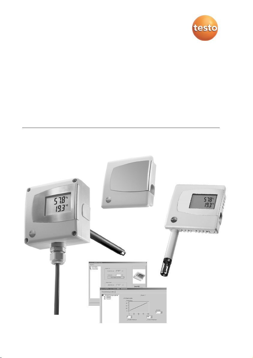
testo 6621
Air-conditioning transmitter for relative humidity and temperature
P2A software for testo 6621
Page 2

2
Page 3

Contents 3
Contents
Contents......................................................................................................3
Safety and the environment..........................................................................4
Part 1: testo 6621
Specifications ..............................................................................................5
Product description....................................................................................10
Commissioning ..........................................................................................12
Assembling the instrument ..............................................................................................12
Wiring the instrument ......................................................................................................14
Parameterizing/adjusting/analyzing the instrument ..........................................................17
Maintaining the product ............................................................................17
Tips and assistance ..................................................................................18
Part 2: testo P2A Software
Specifications ............................................................................................19
First steps ..................................................................................................20
Installing the software / driver ..........................................................................................20
Starting the software ........................................................................................................20
Product description....................................................................................21
Using the product ......................................................................................22
Tips and assistance ..................................................................................26
defresitptsvnl????
Page 4
Safety and the environment4
Safety and the environment
About this document
Please read this documentation through carefully and familiarize yourself with
the product before putting it to use. Keep this documentation to hand so
that you can refer to it when necessary. Hand this documentation on to any
subsequent users of the product.
Pay particular attention to information emphasized by the following symbols:
· With the signal word Caution!:
Warns against hazards which could result in minor physical injury or damage
to equipment if the precautionary measures indicated are not taken.
· Important.
Avoiding personal injury / damage to equipment
Never store the product together with solvents and do not use any
desiccants.
Only operate the product properly, for its intended purpose and within the
parameters specified in the technical data. Do not use force.
Only carry out the maintenance and repair work that is described in the
documentation. Follow the prescribed steps when doing so. Use only OEM
spare parts from Testo.
Protecting the environment
Send the product back to Testo at the end of its useful life. We will ensure
that it is disposed of in an environmentally friendly manner.
Page 5

testo 6621 - Specifications 5
PART 1: TESTO 6621
Specifications
Functions and use
The testo 6621 is a transmitter for relative humidity and temperature. In the A01
(wall/voltage output) (see identification plate), the sensors are located in the
housing; in the A02 (duct) version and the version A03 (wall/current output), the
sensors are located in a permanently connected probe shaft. The transmitter is
available with an integrated display for the reading as an option (cannot be
retrofitted by the customer).
Applications include: Air conditioning, particularly in air conditioning in buildings
and during storage. The product is not suitable for high-humidity drying
processes (relative humidity constantly over 90 %).
The transmitters must only be assembled, wired and connected by qualified
personnel.
The product must not be used in areas at risk of explosion!
defresitptsvnl????
Page 6

testo 6621 - Specifications6
Ordering overview
0555 6621 Axx / Bxx / Cxx / Fxx / Gxx / Mxx / Kxx
A01 Wall version (not with B01/B05)
A02 Duct version
A03 Wall version with external probe for 4...20mA analog output (only with B01)
B01 4 - 20 mA (2-wire, 24 V DC), two analog outputs (humidity/temperature)
B02 0 - 1 V (4-wire, 24 V AC/DC), two analog outputs (humidity/temperature)
B03 0 - 5 V (4-wire, 24 V AC/DC), two analog outputs (humidity/temperature)
B04 0 - 10 V (4-wire, 24 V AC/DC), two analog outputs (humidity/temperature)
B05 4 - 20 mA (2-wire, 24 VDC), humidity: analog output, temperature: passive, Ni1000
B06 0 - 1 V (4-wire, 24 VAC/DC), humidity: analog output, temperature: passive, Ni1000
B07 0 - 5 V (4-wire, 24 VAC/DC), humidity: analog output, temperature: passive, Ni1000
B08 0 - 10 V (4-wire, 24 VAC/DC), humidity: analog output, temperature: passive, Ni1000
C00 Without display
C01 With display
E01 Housing colour light grey, with Testo-Logo (coloured)
E02 Neutral housing, white (RAL9010), without Testo-Logo
E03 Neutral housing, white (RAL9010), with Testo-Logo (black-white)
F01 Relative humidity (% RH)
G02 Temperature (°C) (only with B01 to B04)
G03 Temperature (°F) (only with B01 to B04)
M01 Sintered stainless steel filter (only for A02 and A03)
M02 Metal wire protection cap (only for A02 and A03)
M03 Sintered PTFE filter (only for A02 and A03)
M04 Open metal protection cap (only for A02 and A03)
M05 Open plastic (ABS) cap (only for A02 and A03)
Sample orders
· Duct version with 0 - 10 V outputs, with display, neutral housing without Testo-logo, % RH, °C, open plastic capl:
0555 6621 / A02 / B04 / C01 / E02/ F01 / G02 / M05
· Wall version with 0...5 V outputs, without display, housing colour light grey, % RH, °F: 0555 6621 / A01 / B03/
C00 / E01/ F01 / G03 / K04
Page 7

testo 6621 - Specifications 7
Technical data
Parameters
· Humidity: % RH, temperature: °C/°F
Sensor
· Humidity: Testo humidity sensor, temperature: NTC
· Temperature active signal output: NTC (B01...B04)
·
Temperature passive signal output: NI1000 (B05..B08)
Interfaces
· 1x mini-DIN for / PC
Measuring ranges
· Humidity: 0 - 100 % RH (> 90% RH only briefly)
· Temperature 6621-A01/A03: 0 - +60 °C/32 - 140 °F,
Temperature 6621-A02: -20 - +70 °C/-4 - +158 °F
Measuring medium/pressure range:
· Non-contaminated air (filtered air in air-conditioning
systems or air-conditioned rooms)
· Max. 1 bar positive pressure
Resolution
· Humidity: 0.1 % RH, temperature: 0.1 °C/0.1 °F
Accuracy
· Humidity*: ±2 % RH (0 - 90 % RH), ±4 % RH
(> 90 - 100 % RH)
· Temperature active : ±0.5 °C/0.9 °F
· Temperature passive, Tolerance Ni1000 temperature
sensor (B05 to B08) :
<0 °C: 0.4 °C + (0.028 x |t|)
>0 °C: 0.4 °C + (0.007 x |t|)
Other measurement-related data
· Analog outputs (2 channels each) (Order code B01 to
B04)
· Analog output 1 channel (Order code B05 to B08)
· Meas. cycle: 1/s
· Temperature coefficient (based on 25 °C):
0.05 % RH/K
· Response time t90: <15s at 2m/s
In calibration/ adjustment, observe: The response time
can be considerably higher in still air.
Ambient conditions
· Operating temperature: -20 - 70 °C/-4 - 158 °F (A02),
with display from 0 - 50 °C/32 - 122 °F
· Application temperature: 0...60°C/ 32...140°F
(A01/A03), with display 0...50°C / 32...122°F
· Storage temperature: -40 - 70 °C/-40 - 176 °F
Analog outputs
· 0 - 1 V ±2.5 mV (4-wire)/
0 - 5V ±12.5 mV (4-wire)/
0 - 10 V ±25 mV (4-wire)/
4 - 20 mA ±0.05 mA (2-wire)
· Scaling range: -50…100°C/ -58…212°F,
-50…100%RH
Voltage supply
· 2-wire (4 - 20 mA): 24 V DC ±10 %
· 4-wire (0 - 1 V/0 - 5 V/0 - 10 V): 20 - 30 V AC/V DC
Housing
· Material: ABS
· Dimensions 6621-A01/A03: 81 x 81 x 26 mm, probe
A03 see drawing
Dimensions 6621-A02: 81 x 81 x 42 mm, see
drawing for probe
· Weight 6621-A01: 80 g,
Weight 6621-A02: 160 g
Weight 6621-A03: 90g
· Protection class 6621-A01/6621-A03: IP30,
Protection class 6621-A02: IP65 (with closed cable
screw fitting and connection socket sealed with
rubber plug, or with USB adapter attached)
· Cable couplings 6621-A02: 1 x M16 x 1.5
Display (optional)
· 2-line LCD
Directives, standards and tests
· EC Directive: 2014/30/EC
Guarantee
· Duration: 2 years, warranty conditions see webpage
www.testo.com/warranty
* The determination of the measurement uncertainty
takes place according to GUM (Guide to the
Expression of Uncertainty in Measurement).
In the determination, the accuracy of the measuring
instrument (hysteresis, linearity, reproduceability), the
uncertainty contribution of the test site as well as the
uncertainty of the adjustment site/works calibration
are taken into account. For this purpose, k=2 of the
extension factor, the usual value in measurement
technology, is used as a basis, corresponding to a
trust level of 95%.
defresitptsvnl????
Page 8
testo 6621 - Specifications8
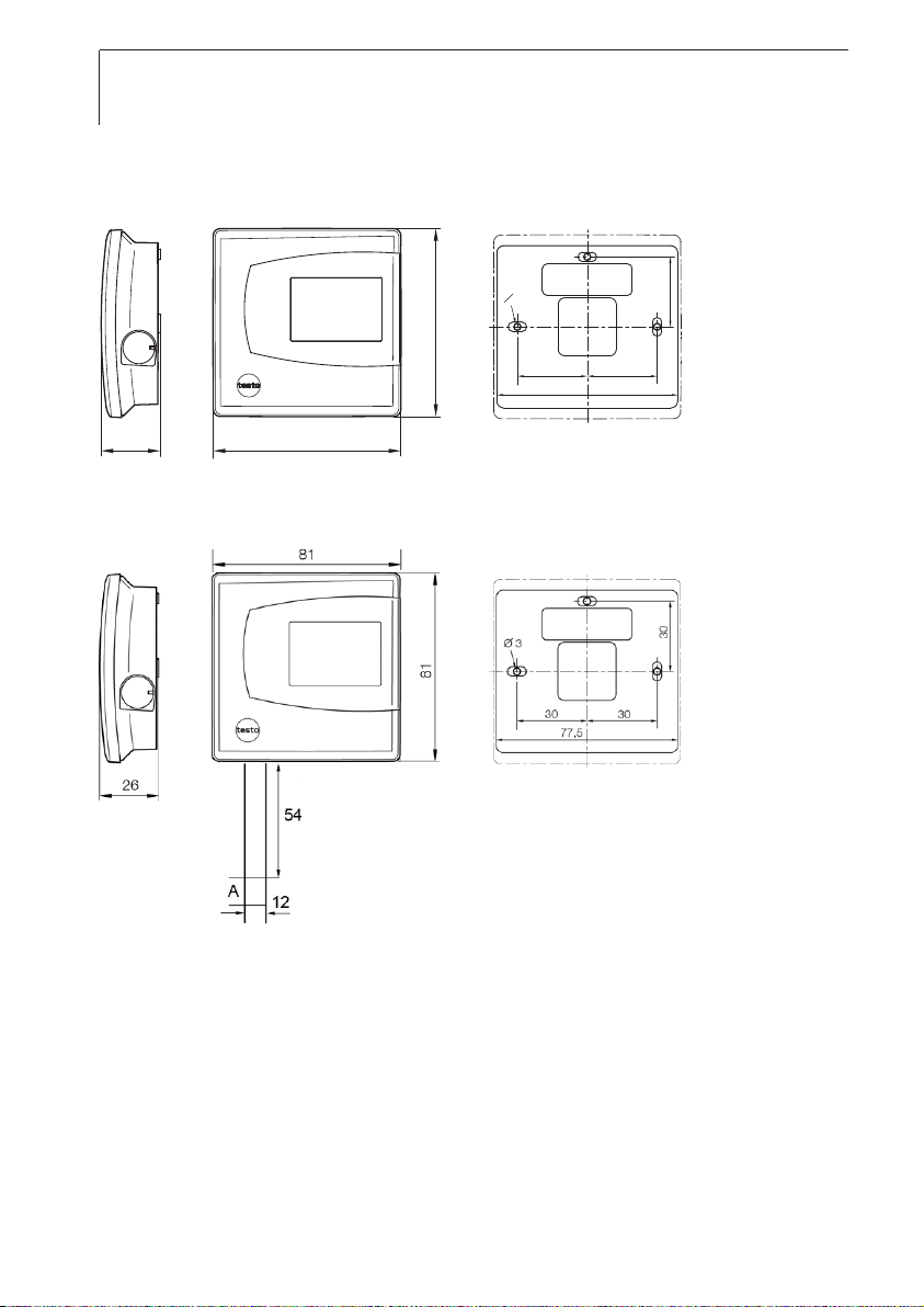
Dimensions
testo 6621-A01 (wall):
testo 6601-A03 (wall/current version):
81
26
81
O 3
30
30
30
77,5
Page 9
testo 6621 - Product description 9
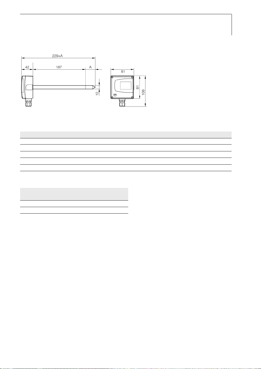
testo 6621-A02 (duct):
A = length of sensor protection cap used
Sensor protection cap Order code Length A in mm
Sintered stainless steel filter M 01 33
Wire mesh filter M 02 40.3
Sintered PTFE filter M 03 35
Metal protection cap (open) M 04 35
Plastic protection cap (open) M 05 25
Choice of filter dependent on exposure to particles:
Velocity Exposure to particles
none fine coarse
< 7 m/s M04/05 M02 M03
> 7 m/s M 01 M02* M01*
* also use condensation protection 0554 0166, serves as flow protection
defresitptsvnl????
Page 10

testo 6621 - Commissioning10
Product description
At a glance: testo 6621-A01 (wall/voltage version)
Top part of housing, display (option,
cannot be retrofitted) for displaying
readings:
1st line Relative humidity (duct 1),
2nd line Temperature (duct 2).
Mini-DIN port.
Opening for feeding cable through from
underneath, predetermined breaking
point in housing wall
At a glance: testo 6621-A03 (wall/curent version)
Housing cover, display (option, not
retrofittable) for measurement value
display:
1 line relative humidity (channel 1),
2 line temperature (channel 2).
Mini-DIN-connection socket.
Opening for cable inertion from below,
break-out point in housing wall.
Probe shaft
Sensor protection cap
Page 11

testo 6621 - Commissioning 11
At a glance: testo 6621-A02 (duct)
Top part of housing, display (option,
cannot be retrofitted) for displaying
readings:
1st line Relative humidity (duct 1),
2nd line Temperature (duct 2).
Mini-DIN port, protected by rubber plug.
Probe shaft.
Sensor protection cap.
Cable coupling for feeding cable through.
4 screws (Phillips) for fastening the top
part of the housing.
defresitptsvnl????
Page 12

testo 6621 - Commissioning12
Commissioning
Assembling the instrument
➣
Assembling the testo 6621-A01/03 (wall):
Please note that assembling the instrument on poorly insulated exterior walls
will result in humidity and temperature readings that do not reflect the
average values in the room. It is recommended that the instrument be
installed on well insulated exterior or interior walls.
1 To open the housing (no connector may be inserted in the mini-DIN
socket): lift up the upper part of the housing () and remove ().
2 Guide the cable from behind (
) or underneath (, detach pre-punched
area of the housing) into the lower part of the housing.
3 Depending on the conditions in situ: Fasten lower part of housing at the
slots () using appropriate screws (not supplied).
4 After wiring (see chapter Wiring the instrument): Replace the upper part of
the housing.
Page 13

testo 6621 - Commissioning 13
➣
Assembling the testo 6621-A02 (duct):
1 Assemble the instrument according to the conditions in situ.
The illustration below shows the instrument assembled on a duct with the
wall/duct holder (accessory, 0554 6651) as an example:
The illustration below shows the instrument assembled on a wall with the
wall/duct holder (accessory, 0554 6651) as an example:
testo 6621-A02 (duct).
Probe shaft.
Wall/duct holder (accessory 0554 6651),
for assembly on wall with spacer.
Fastening screws (customer-specific, not
included).
Locking screw for fastening the probe
shaft.
defresitptsvnl????
Page 14

testo 6621 - Commissioning14
2
To open the housing: Loosen the 4 screws in the upper part of the
housing () and remove the upper part of the housing ().
3 Guide the cable through the cable coupling (
) into the lower part of the
housing.
4 After wiring (see below): Close the cable coupling to fix the cable (right-
handed thread) and replace upper part of housing.
Wiring the instrument
Make sure when routing the cables that there is space between the
signal lines and interfering external lines.
If electromagnetic interference is likely, use a shielded and/or twisted
cable. The shield must be connected to earth on the side facing away
from the transmitter. Recommendation: 8-wire line with a tightly plaited
shield, wire cross-section of 0.25 - 0.5 mm².
If overvoltages are likely, install overvoltage protection devices.
Wire the instrument according to the application in hand:
2-wire/4-wire technology (2 analog outputs active)
testo 6621 (wall)
View of wiring side (rear of housing)
➊
Voltage output A01 (4-wire,
0 - 1 V/0 - 5 V/0 - 10 V):
U = 20 - 30 VDC/AC
➋ Current output A03
(2-wire, 4...20 mA),
max. load 500 W
123456
+-+-+-
UrHT
6
5
4
3
+
-+-
rH
T
+
-
U
➋
123456
Page 15

testo 6621 - Maintaining the product 15
testo 6621-A02 (duct)
View of wiring side
➌
Voltage output (4-wire,
0 - 1 V/0 - 5 V/0 - 10 V):
U = 20 - 30 VAC/DC
➍
Current output (2-wire,
4 - 20 mA), max. load 500 W
2-wire/4-wire technology (1 analog output active for humidity,
1 passive temperature signal output)
testo 6621-A01 (wall)
View of wiring side (rear of housing)
➊
Voltage output A01 (4-wire,
0...1V / 0...5V / 0...10V):
U = 20...30VDC/AC,
Temperature signal output
Ni1000 passive
testo 6621-A02 (duct)
View of wiring side
➋ Voltage output (4-wire,
0...1V / 0...5V / 0...10V):
U = 20...30VAC/DC,
Temperature signal output
Ni1000 passive
➌
Current output (2-wire,
4...20mA), max. load 500W,
Temperature signal output
Ni1000 passive
654321
+-+-+-
T rHU
6543
+
-+-
rH T
+
-
U
+
-
U
defresitptsvnl????
UrHT
+-+-+123456
➋
TrHU
+-+-+-
654321
+
U
-
rH
+-
T
+-
6543
+
U
-
Page 16

testo 6621 - Tips and assistance16
3-conductor technology (2 analog outputs active)
All earth connections are connected to each other (= one common earth).
Attention! Incorrect polarity wil destroy the instrument (instrument not reverse
polarity-proof).
Connections for voltage supply: connect common earht to pin 2!
testo 6621-A01 (Wall)
View of wiring side (rear of housing)
testo 6621-A02 (Duct)
View of wiring side
UrHT
+-+-+123456
+
-
rH T
+
+
-
U
1
23456
24V~
~
+
-
-
Page 17

testo P2A Software - Specifications 17
Parameterizing/adjusting/analyzing the
instrument
The analog outputs can be scaled in the following ranges, beyond the
measurement range of the measurement transmitter: -50…100°C/
-58…212°F, -50…100%RH.
The instrument is parameterized, adjusted and analyzed using the P2A
Software, see “Part 2: testo P2A Software”.
Maintaining the product
➢
Cleaning the housing:
Clean the housing with a damp cloth (soap suds) if it is dirty. Do not use
aggressive cleaning agents or solvents!
➢
Cleaning the sensor of the testo 6621-A01 (wall/voltage version):
Do not touch sensor.
Open the housing and carefully clean the reflective surface of the sensor
(top right, assembled vertically on the circuit board) with distilled water or
ethanol. Allow the sensor to dry completely.
➢
Cleaning the sensor of the testo 6621-A02 (duct), testo 6621-A03
(wall/current version):
Do not touch sensor.
Unscrew the sensor protection cap and carefully rinse the reflective
surface of the sensor with distilled water or ethanol. Allow the sensor to
dry completely.
➢
Cleaning the filter of the testo 6621-A02 (duct), testo 6621-A03
(wall/current version):
If using a sintered filter:
Clean regularly by blowing out with compressed air or ultrasonic bath,
depending on the level of contamination created by the process.
defresitptsvnl????
Page 18

testo P2A Software - First steps18
Tips and assistance
Questions and answers
Question Possible causes / solutions
Signal response too slow. · Clean the filter
If we could not answer your question, please contact your dealer or Testo
Customer Service. For contact data, see back of this document or web page
www.testo.com/service-contact.
Accessories and spare parts
Designation Article no.
Parameterizing, adjusting and analyzing software (P2A Software incl. adapter cable for USB to mini-DIN) 0554 6020
Control and adjustment set for 2-point adjustment (11.3 % and 75.3 % RH), only for testo 6621 - A02 0554 0660
Wall/duct holder 0554 6651
Replacement sensors (% RH) for testo 6621-A02 0420 0023
Mains unit (bench unit), 110 - 240 V AC/24 V DC (350mA) 0554 1748
Mains unit (top-hat rail mounting), 90 - 264 V AC/24 V DC (2.5A) 0554 1749
ISO calibration certificate for humidity at 11.3% and 75.3% RH 0520 0076
ISO-calibration certificate humidity 0520 0176
Sintered stainless steel filter 0554 0647
Wire mesh filter 0554 0757
Sintered PTFE filter 0554 0759
Metal protection cap (open) 0554 0755
Plastic protection cap (open) 0192 0265
For a complete list of all accessories and spare parts, please refer to the
product catalogues and brochures or look up our website at: www.testo.com
Page 19

testo P2A Software - Product description 19
PART 2: TESTO P2A SOFTWARE
Specifications
Functions and use
The P2A software is used for the parameterization, adjustment and analysis of
Testo transmitters. The following applies:
• If a Testo transmitter is bought at a later stage (and is therefore more recent
than the existing P2A software version), a software update is required.
• You can find the free upgrade on the Testo website www.testo.com under
the product-specific downloads.
• The software therefore only needs to be bought once, even for owners of
several Testo transmitters.
System requirements
Operating system
· Windows XP®, Windows®Vista, Windows®7, Windows®8 oder Windows®10
Computer
The computer must meet the requirements of the operating system in each
case. The following requirements must also be met:
• USB 1.1 interface or higher
• Graphics resolution of at least 1024 x 768
• Date and time settings are automatically adopted by the PC. The
administrator must make sure that the system time is regularly compared with a
reliable time source, and adjusted if necessary, in order to ensure the
authenticity of the data
defresitptsvnl????
Page 20

testo P2A Software - Product description20
First steps
Installing the software / driver
Administrator rights are required for the installation of the testo P2A
Software.
➢
Installing the P2A Software:
Installing P2A software:
1.
Insert CD with the P2A software.
✓ If the installation program does not start automatically:
> open Windows Explorer and start the setup.exe file on the software CD.
2. Follow the instructions of the installation wizard.
➢
Installing the USB drivers:
The USB driver CD is supplied with the P2A Software.
Before installing the USB drivers, please read the separate documentation
enclosed with the USB driver CD.
The installation of the USB driver is the prerequisite for the faultless use of
the P2A software.
➢
P2A Software update:
P2A software update
1.
You can find the P2A software upgrade on the Testo website
www.testo.com under the product-specific downloads. Download and
save P2A software upgrade.
2. Start P2A upgrade.exe file.
3. Follow the instructions of the installation wizard.
Starting the software
➢
Starting the program:
Windows program menu
W
indows 2000®SP4, Windows®XP or Windows®Vista
> Click on [Start] > All Programs > Testo > P2A Software (double-click on
left mouse button).
Page 21

testo P2A Software - Using the product 21
Windows® 7
> Click on [Start] > All Programs > Testo > P2A Software (double-click on
left mouse button).
Windows® 8
> Click on [Start] | right mouse button | Search | Enter the name of the
application in the search field | P2A Software. (double-click on left mouse
button).
Windows® 10
> Click on [Start] | All Apps | Testo | P2A Software. (double-click on left
mouse button).
Product description
User interface
Menu bar.
Toolbar.
File list: List of all instrument/parameter files.
File symbols
· : Instrument file, connection to the unit has not been established.
· : Instrument file, connection to the unit has been established.
· : Parameter file.
defresitptsvnl????
Page 22

testo P2A Software - Using the product22
File identifications
· Instrument files: “[Type] [serial number].cfm”; file identifications cannot be changed.
Instrument files contain all the data relating to a particular instrument. These are the parameter data and
represent the parameterization and adjustment history of the instrument.
· Parameter files: “[Type] [serial number] [date] [time].cfp”; file identifications can be changed.
Parameter files only contain parameter data. These can be copied to another instrument or parameter file for
the same type of instrument so that several instruments have the same parameter settings.
List of functions.
Instrument information:
Information displayed
· Instrument files: Type, serial number, firmware version and connection status of the instrument.
· Parameter file: Type, serial number and firmware version of instrument with which the parameter file was
created.
· Connection status (instrument files only): “green” connection is active, “red” connection is inactive.
Using the product
➢
Establishing a connection with the device:
Several instruments can be connected to the PC and administered via the
P2A software, but only one connection can ever be active at any one time.
Non-wired instruments can also be connected to the P2A Software for
parameterization/adjustment. The supply to the instruments is then effected
via the USB interface (analog outputs not functional).
1 Connect the USB/mini-DIN adapter to the external interface (mini-DIN) of
the instrument.
2 Connect the USB connector of the adapter to the PC.
- The instrument file for the instrument connected appears in the
instrument file/parameter file list.
➢
Selecting the instrument/parameter file, activating a connection with the
device:
Click on the requisite instrument/parameter file.
- The selected file is highlighted in colour.
- For instrument files only: if a connection with the instrument has been
established, this is automatically activated.
Page 23

testo P2A Software - Using the product 23
➢
Changing an instrument/parameter file:
✓ The required instrument/parameter file is selected.
1 Click on Change parameterization button.
2 Select channel.
3 Enter parameters in the corresponding fields.
4 Click on Apply to confirm entries.
5 To leave the parameterization screen, click on OK.
➢
Saving the parameters in a parameter file:
The parameter data for the selected instrument/parameter file can be saved.
Only parameter data stored in the standard file can be loaded into an
instrument!
✓ The required instrument/parameter file is selected.
1 In the menu bar, click on File > Save as.
2 Select the storage location and enter the file name.
3 Click on Save to confirm entries.
➢
Opening a parameter file:
All parameter files stored in the standard directory path are automatically
displayed in the file list when the software is started. Parameter files stored in
other directories can also be opened.
Only parameter data stored in the standard file can be loaded into an
instrument!
1 In the menu bar, click on File > Open.
2 Select the storage location and click on the requisite parameter file.
3 Click on Open to confirm entries.
➢
Copying the parameter data:
The parameter data for an instrument/parameter file can be transferred to
another instrument/parameter file for the same type of instrument. History
data for instrument files are not transferred.
1 Select file from which the parameter data are to be copied.
2 In the menu bar, click on Edit > Copy.
3 Select the file which is to be modified.
4 In the menu bar, click on Edit > Paste.
defresitptsvnl????
Page 24

testo P2A Software - Using the product24
➢
Analyzing/testing the instrument:
✓ The required instrument file is selected.
1 Click on Test / analyze transmitter button.
2 Perform tasks:
Options
· Carry out factory reset: Reset the parameter unit, scaling limits and adjustment to the factory settings
(Values instrument-specific, see specification plate).
· Transmitter tests (voltage supply via terminals required): Current reading displayed and analog output test
carried out for each channel; see below for procedure.
· Min./max. values: Change to display of minimum/maximum values.
Procedure: testing analog output (voltage supply via terminals required)
1 Choose channel.
2 Connect reference multimeter (min. 6.5 digits resolution) to the analog output terminals of the transmitter.
3 Set the default value in the P2A Software and click on
Activate.
4 Compare value displayed with reference value of multimeter.
3 To leave the analyzing/test screen, click on OK.
➢
Carrying out/resetting a 1-point adjustment (offset):
Make sure that the reference instrument has a higher level of accuracy
than the test specimen!.
1 Click on Adjust transmitter button.
2 Select the channel under 1-point adjustment.
3 Expose the reference measuring instrument and the instrument to be
adjusted to the same constant conditions and wait for equalization period
to lapse.
4 Enter reference value and perform adjustment by clicking on Carry out 1-
point adjustment.
To reset an offset value, click on Set Offset to zero.
5 Click on OK to confirm entries.
➢
Carrying out a 2-point adjustment:
1 Click on Adjust transmitter button.
2 Select the adjustment point under 2-point adjustment.
3 Position the entire testo 6621-A01 (wall) or the probe shaft of the testo
6621-A02/A03 in a precision humidity generator/air conditioning cabinet
and route the USB cable to the P2A Software outwards.
4 To set the humidity generator: Temperature of 25 °C and humidity of
11.3 % RH or 75.3 % RH (depending on adjustment point chosen).
Page 25

Notes 25
5
After a sufficient equalization period (at least 1.5 h): Enter reference value
and perform adjustment by clicking on Lower adjustment point or Upper
adjustment point (depending on adjustment point chosen).
6 Repeat steps 3 to 5 for the second adjustment point accordingly.
7 Click on OK to confirm entries.
For the testo 6621-A02/A03 (duct), a 2-point adjustment can also be
performed using the testo control and adjustment set (0554 0660). Please
also refer to the instruction manual for the control and adjustment set. The
reference values are entered and the adjustment is carried out in the same
way as for an adjustment with a humidity generator/air conditioning
cabinet (see steps
5 to 7).
➢
Carrying out an analog adjustment:
Voltage supply via terminals required.
1 Click on Adjust transmitter button.
2 Choose channel.
3 Connect reference multimeter (min. 6.5 digits resolution) to the analog
output terminals of the transmitter.
4 Click on Start Wizard... button and follow the instructions issued by the P2A
Software.
5 Click on OK to confirm entries.
➢
Viewing a transmitter history:
The current history data are always displayed as stored in the instrument file.
A distinction is made between parameterization and adjustment histories.
Dates and times refer to the PC time when the P2A Software was being
used.
History data are only stored in the instrument file (PC), not in the
testo 6621.
1 Click on Transmitter history button.
2 To move between the views, click on Parameterization history or Adjustment
history.
To print the history data, click on Print.
defresitptsvnl????
Page 26

Notes26
➢
Deleting parameters from an instrument/parameter file:
The parameter data for the selected instrument/parameter file can be
deleted.
✓ The required instrument/parameter file is selected.
1 Right-click on the instrument/parameter file.
2 Select Delete.
3 Click on Yes to confirm.
➢
Creating a new folder:
✓ The folder to which the new folder is to be added is selected.
1 In the menu bar, click on File > Add Folder.
2 Give the new folder a name.
Tips and assistance
Questions and answers
Question Possible causes/solutions
Connection to instrument cannot
be established. · Check connecting cable and plug contacts.
· USB driver not/incorrectly installed: Re-install.
Adjustment is to be reversed. · Carry out factory reset: Click on
Test/ analyze transmitter > Click
on Carry out factory reset.
If we could not answer your question, please contact your dealer or Testo
Customer Service. For contact data, see back of this document or web page
www.testo.com/service-contact.
Page 27

Notes 27
defresitptsvnl????
Page 28

0970 6620 en 07
 Loading...